
Related Manuals for FOR-A MFR-6000


Summary of Contents for FOR-A MFR-6000
- Page 1 OPERATION MANUAL MFR-6000 Multi Format Routing Switcher MFR-GPI MFR-TALM Edition - Rev.1...
- Page 2 Edition Revision History Edit. Rev. Date Description Section/Page 2018/10/22 First edition 2019/04/19 Description errors corrected. Throughout...
- Page 3 Precautions Important Safety Warnings [Power] Operate unit only at the specified supply voltage. Caution Disconnect the power cord via the power plug only. Do not pull on the cable portion. Do not place or drop heavy or sharp-edged objects on the power cord. A damaged cord can cause fire or electrical shock hazards.
- Page 4 [Circuitry Access] Do not remove covers, panels, casing, or access the circuitry with power applied to the unit. Turn the power off and disconnect the power cord prior to removal. Internal servicing / adjustment of unit should only be performed by qualified personnel. Do not touch any parts / circuitry with a high heat factor.
- Page 5 OpenSSL This product includes software developed by the OpenSSL Project for use in the OpenSSL Toolkit (http://www.openssl.org/) Freetype Portions of this software are copyright © 2005 The FreeType Project (www.freetype.org). All rights reserved. Lighttpd Copyright © 2004, Jan Kneschke, incremental. All rights reserved. Redistribution and use in source and binary forms, with or without modification, are permitted provided that the following conditions are met: - Redistributions of source code must retain the above copyright notice, this list of conditions and the following disclaimer.
- Page 6 Upon Receipt MFR-6000 units and their accessories are fully inspected and adjusted prior to shipment. Check your received items against the packing lists below. Check to ensure no damage has occurred during shipment. If damage has occurred, or items are missing, inform your supplier immediately.
- Page 7 Shaded text (such as ON) indicates parameter values in the menu. Text enclosed by a square (such as ALARM, MODE) indicates front panel buttons on the MFR-6000 or Remote Control Units. References to the MFR Series Web-based Control Software are indicated by [Web-based...
-
Page 8: Table Of Contents
Table of Contents 1. Prior to Starting ...........................10 1-1. Overview ...........................10 1-2. Features ............................10 2. Panel Descriptions ..........................11 2-1. MFR-6000 Front Panel ......................11 2-1-1. Matrix Size Chart .......................12 2-2. MFR-6000 Rear Panel ......................14 2-2-1. Interfaces ...........................15 2-3. SDI Input/Output Cards ......................17 2-3-1. - Page 9 6-3-5. Destination Lock Status Request Command (9) ..............61 6-3-6. Channel Name Import Commands (10) ................62 7. Troubleshooting ..........................63 8. Specifications and Dimensions ......................64 8-1. Unit Specifications ........................64 8-1-1. MFR-6000 ..........................64 8-1-2. MFR-GPI ..........................66 8-1-3. MFR-TALM ........................66 8-2. External Dimensions .........................67 8-2-1. MFR-6000 ..........................67 8-2-2.
-
Page 10: Prior To Starting
1. Prior to Starting 1-1. Overview The MFR-6000 is a multi-format routing switcher that supports 12G-SDI, 3G-SDI, HD-SDI, SD-SDI, and ASI signals. Inside the 13U case a matrix of up to 144 inputs/ 144 outputs can be configured. It supports various functions such as the capability of linking multiple units, tally connections with peripheral devices, and automatic source name tracking, to allow the units to be the core product in A/V systems. -
Page 11: Panel Descriptions
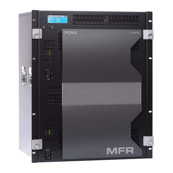
2. Panel Descriptions 2-1. MFR-6000 Front Panel POW ER CPU1 CPU2 MFR-6000 ROUTING SW ITCHER POWER 1 POWER 2 Name Description POWER1 Switch used to turn unit power ON / OFF. POWER2 Switch used to power ON / OFF the optional power supply. -
Page 12: Matrix Size Chart
2-1-1. Matrix Size Chart Standard SDI Signal Routing Matrix size varies depending on the number of installed MFR-9SDI12G and MFR-9SDO12G cards as shown below. (144 x 144 to 9 x 9) Number of cards: MFR-9SDO12G... - Page 13 Matrix size varies depending on the number of installed MFR-8SDIEX, MFR-8SDOEX, MFR-2SDIGB and MFR-2SDOGB cards as shown below. (128 x 128 to 8 x 8) Number of cards: MFR-8SDOEX / MFR-2SDOGB...
-
Page 14: Mfr-6000 Rear Panel
FAN4 FAN3 FAN2 FAN1 INPUT OUTPUT OUTPUT INPUT *The above figure shows an MFR-6000 with MFR-9SDI12G and MFR-9SDO12G cards installed. Name Description MFR-LAN Ethernet ports for connection to MFR Remote Control Units and MFR-GPI (CPU1 / CPU2) (10/100BASE-TX, RJ-45) PC-LAN... -
Page 15: Interfaces
2-2-1. Interfaces SERIAL Connector (9-pin D-sub, male) Select RS-232C or RS-422 using the slide switch at the bottom of the connector. RS-232C Connector Pin Assignments Pin No. Signal Name Description Not used Received Data Transmitted Data Data Terminal Ready Signal Ground Data Set Ready Request to Send... - Page 16 ALARM Connector (9-pin D-sub, female) Alarm 1 Out: Normal operation: Pins 1 and 6 are open. Malfunction or power-off: Pins 1 and 6 are closed. Alarm 2 Out: Normal operation: Pins 2 and 7 are open. Malfunction or power-off: Pins 2 and 7 are closed.
-
Page 17: Sdi Input/Output Cards
2-3. SDI Input/Output Cards SDI input/output cards are available to install slots shown on the table and figure below. ► See Sec. 2-1-1. “Matrix Size Chart” for details. REF IN Slot No Input/ Output Cards CPU2 CPU1 ALARM 232C MFR-9SDI12G SERIAL 01-04 MFR-8SDIEX... - Page 18 2-3-2. MFR-9SDO12G BNC x 9 outputs (12G/3G/HD/SD-SDI and ASI) Set up output signals in the Web-based Control Software as shown below. Destination Name Open the [Web-based Control: ROUTER SYSTEM SETTINGS - Destination Name page]. This page allows you to change destination names displayed on Remote Controllers or other devices.
-
Page 19: Mfr-8Sdoex
2-3-4. MFR-8SDOEX BNC x 8 outputs (3G/HD/SD-SDI and ASI) Destination Name Open the [Web-based Control: ROUTER SYSTEM SETTINGS - Destination Name page]. This page allows you to change destination names displayed on Remote Controllers or other devices. Destination Assignment Open the [Web-based Control: ROUTER SYSTEM SETTINGS - Destination Assignment page]. -
Page 20: Mfr-2Sdogb
2-3-6. MFR-2SDOGB The MFR-2SDOGB is a 12G/3G-SDI output card. Its Gearbox function enables conversion between 12G-SDI and Quad Link 3G-SDI signals, and between 2SI and SQD signals. The following listed SDI signals can be output. 12G-SDI: Max. 2 outputs (If installed into Input 1-8: BNC 1D, 2D If installed into Input 9-16: BNC 1A, 2A) ... -
Page 21: Mfr-Gpi
2-4. MFR-GPI 2-4-1. Front Panel MFR-GPI GPI UNIT SERIAL POWER BUSY GPI 1 RESET Item Description Displays the power status. POWER ► See the table below for details on indications. Displays the flash memory writing status of backup settings. BUSY ►... -
Page 22: Rear Panel
2-4-2. Rear Panel SERIAL SERVICE RATING LABEL 2 -DC12V IN- 1 MFR-LAN GPI 1 GPI 2 GPI 3 GPI 4 Item Description Used to connect the MFR main unit MFR-LAN Ethernet port (10/100 BASE-TX) SERVICE Used for maintenance only. Do not use. DC12V IN 1, 2 Used to supply 12V DC power. -
Page 23: Interfaces (Mfr-Gpi)
2-4-3. Interfaces (MFR-GPI) GPI IN / TALLY OUT Connector (37-pin D-sub, female) Pin No. Signal Pin No. Signal GPI_IN / TALLY_OUT 01 # GPI_IN / TALLY_OUT 20 # GPI_IN / TALLY_OUT 02 # GPI_IN / TALLY_OUT 21 # GPI_IN / TALLY_OUT 03 # GPI_IN / TALLY_OUT 22 # GPI_IN / TALLY_OUT 04 # GPI_IN / TALLY_OUT 23 #... - Page 24 GPI OUT / TALLY OUT Circuit MFR-GPI External device Max. voltage: 40V Max. Current: 100mA 10Ω Approx. 0.9V when turned-on...
-
Page 25: Card Switches
Further note that adjustments and maintenance should only be performed CAUTION by qualified technical personnel familiar with FOR-A equipment. Remove the two screws on both sides of the MFR-GPI to access the internal card as shown below. The figure below shows the factory default switch settings. -
Page 26: Mfr-Talm
2-5. MFR-TALM 2-5-1. Front Panel MFR-TALM TALLY MAN AGER UNIT POWER BUSY REF IN RS-422 RESET ITEM Description Displays power status. POWER ► See the table below for details on indications. Displays the flash memory writing status of backup settings. BUSY ►... -
Page 27: Rear Panel
2-5-2. Rear Panel RS-422 DC12V IN PC-LAN MFR-LAN REF IN SER. NO. ITEM Description Ethernet port for connection to PC or other external unit PC-LAN (10/100BASE-TX, RJ-45) Ethernet port for connection to MFR main unit MFR-LAN (10/100/1000BASE-T, RJ-45) Used to input a reference signal (BB or Tri-level sync signal) REF IN (with loop-through. -
Page 28: System Configuration Example
The block diagram below shows an example of the basic MFR routing system that consists of an MFR-6000, Remote Unit and the Web-based Control accessed from a computer. Make sure to connect both MFR-LANs (CPU1) and (CPU2) to a LAN respectively for CPU redundancy. -
Page 29: Main Unit Linking
Connect all devices in the MFR system as shown in the figure above. Power on the MFR-6000 to be set as a Master, Remote Control unit and PC. Set the IP addresses for the Remote Control unit (1) and PC (4). Power off the Master MFR-6000. -
Page 30: Configuring The System With Mfr-Talm
Power on the Slave MFR-6000. Set the IP addresses (5 and 6) as shown in the previous page. Power on the Master MFR-6000. Open the Master MFR-6000 Web-based control and go to the Build Settings page. Check on Build Enable to enable the Main Unit Link feature. - Page 31 Transmitting Signal Name and Tally Data The figure below shows an example signal name and tally data routing system using the MFR-TALM. MFR-6000 MFR- MFR- Video Switcher 9SDI12G 9SDO12G (HVS-2000) OUT1 RS-422(1) RS-422(4) IN144 OUT144 MFR-LAN PC-LAN Multi Viewer...
- Page 32 TCP/IP Setting Open the [MFR-TALM Web-based Control: Port Settings page] and perform port settings under TCP/IP Port. [Port Settings] - [TCP/IP Port] Port Menu Access IP Address Port Function Method Web-based Control (MV TCP/IP TSL UMD protocol Client port number) IP address) V5.0 Tally out [TALM Settings]...
-
Page 33: Switcher's Aux Crosspoints Switching System
Assume that the system is configured as shown below: AUX1 on the switcher is assigned to DST 201 (Level 1) on the MFR-6000. IN1-8 on the switcher are assigned to SRC201-208 on the MFR-6000 and STL (Still) 3 is assigned to SRC209. - Page 34 Connect and assign video signals as shown in the figure on previous page. Device Setup on the MFR-6000: Connect to the MFR-6000 from the Web-based Control PC and open the [Tally System Settings - Device Select] page. Select HVS-390HS in the [Switcher] field and click [Send].
-
Page 35: Synchronous Crosspoints Switching
Assign IN1 to SRC 201. After above setup settings are complete: If SRC 201 is selected for DST 201 on the MFR-6000, IN1 is selected for AUX1 on the switcher. If SRC 3 is selected for DST 201 on the MFR-6000, IN9 is selected for AUX1 on the switcher and SRC 3 is also selected for DST 112 on the MFR-6000. -
Page 36: Menu Display Operation
4. Menu Display Operation Removing the front panel reveals menu display operation buttons. STATUS CONTROL CANCEL Button Description Opens STATUS menu. (STATUS menu is displayed when button is STATUS lit.) Lit: Displays the menu display. CANCEL Unlit: Returns to a menu selection using the icons on top. CONTROL Moves between menu icons. -
Page 37: Status
4-1. STATUS Displays various status. “Getting...” is displayed for items acquiring data. When settings are changed in each menu, the following messages are displayed. (Example below is [STATUS > INFO] menu.) Now sending settings… Do not power off. Reboot is required to apply setting. 4-1-1. -
Page 38: Status > Mfr-Lan
4-1-2. STATUS > MFR-LAN Displays MFR-LAN CPU1 and CPU2 IP and Subnet mask addresses. 4-1-3. STATUS > PC-LAN Displays PC-LAN CPU1 and CPU2 IP, Subnet mask and Gateway addresses. 4-1-4. STATUS > SLOT Move into [STATUS > SLOT] menu where a slot can be selected by pressing CONTROL. Select a slot by turning CONTROL and push CONTROL to decide a slot to display the installed card information. -
Page 39: Status > Power
4-1-5. STATUS > POWER Displays power supply status for each card and power supply unit. Item Description CPU1 CPU2 MATRIX NORMAL: Normal ERROR: Power supply error occurred. FRONT REAR1 REAR2 NORMAL: Normal PS1 AC, DC POWER OFF: Power off NORMAL: Normal PS2 AC, DC NOT INST.:... -
Page 40: Status > Fan
4-1-7. STATUS > FAN Status of MFR-6000 rear fan (REAR 1-7) and power supply fan (PS1-2) units. Item Description REAR 1-7 NORMAL: Normal WARNING: Warning PS1-2 ERROR: Fan error 4-1-8. STATUS > VERSION Displays FW (Firmware), FPGA and CPLD version for each card. -
Page 41: Setting
4-2. SETTING Turn CONTROL to select a menu to change settings and press CONTROL to enter the settings screen. Menu Description SWAP ACTIVE CPU Allows you to verify CPU condition and manually swap the active CPU. SLOT SHUTDOWN Allows you to turn on/off an in/out card. POWER SUPPLY 2 Allows you to verify power supply 2 installation and change settings. -
Page 42: Changing Power Supply 2 Installation Status
Turn press CONTROL select EXECUTE in CHANGE STATE. A Now Executing… message is displayed. When SHUTDOWN displayed, slot shutdown is complete. Example) Turning ON the INPUT5 slot. Open [SETTING > SLOT SHUTDOWN] menu. Turn and press CONTROL to select INPUT5 in TARGET SLOT. -
Page 43: Changing Menu Display Settings
4-2-4. Changing Menu Display Settings Open the [SETTING > FRONT DISPLAY] menu to change MFR-6000 menu display settings. When the menu is not displayed, press the CANCEL button to display the menu. Changing Menu Display Brightness Open the [SETTING > FRONT DISPLAY] menu. -
Page 44: Gearbox Feature (Mfr-2Sdigb / 2Sdogb)
When a 12G-SDI signal is input to a Gearbox, other connectors are disabled. MFR-2SDIGB MFR-2SDOGB 12G/3G-SDI 12G/3G-SDI 3G-SDI 3G-SDI Gearbox 1 Gearbox 1 3G-SDI 3G-SDI 3G-SDI 3G-SDI MFR-6000 routing Gearbox 2 Gearbox 2 Supported formats Signal format; Video format Standard 3840 x 2160/59.94p 4:2:2 SMPTE 12G-SDI... -
Page 45: Available Conversions
5-2. Available Conversions MFR-2SDIGB / 2SDOGB cards allow following input/output conversions. Reference Signal: REF IN Total Delay Delay (H) Reference Signal: SDI Input (When installed into Input 1-8/ Output 1-8) - When SDI Input is selected in MFR-2SDOGB, input signals are synchronized only when all 4 channels are input to the Gearbox. - In case of Input 9-16 /Output 9-16, read the table by swapping Gearbox 1 and Gearbox 2. -
Page 46: Conversion Settings
Quad Link Quad Link Gearbox 1 3G-SDI 3G-SDI MFR-6000 (SQD) (2SI) routing Open the Gearbox Settings page in the WebGUI and select signal formats under From and To as shown below for a Gearbox in the MFR-2SDIGB card block. (This example sets Gearbox 1 on the Slot 4 card.) -
Page 47: Converting 2Si To Sqd Output (Mfr-2Sdogb)
5-3-2. Converting 2SI to SQD Output (MFR-2SDOGB) MFR-2SDOGB Quad Link Quad Link Gearbox 1 MFR-6000 3G-SDI 3G-SDI (2SI) (SQD) routing Open the Gearbox Settings page in the WebGUI and select signal formats under From and To as shown below for a Gearbox in the MFR-2SDOGB card block. (This example sets Gearbox 1 on the Slot 15 card.) -
Page 48: Converting 3G-Sdi Sqd To 12G-Sdi (Mfr-2Sdogb)
5-3-4. Converting 3G-SDI SQD to 12G-SDI (MFR-2SDOGB) MFR-2SDOGB Quad Link Gearbox 1 MFR-6000 3G-SDI (SQD) routing 12G-SDI Open the Gearbox Settings page in the WebGUI and select signal formats under From and To as shown below for a Gearbox in the MFR-2SDOGB card block. (This example sets Gearbox 1 on the Slot 15 card.) -
Page 49: Sdi Bnc Output Settings
Adding 8K Quad-Link Payload ID Information. When converting 3G Quad-Link to 12G-SDI, Payload ID information for 8K Quad-Link (In compliance with SMPTE 2082-1) is able to be added to 12G-SDI output. Set as shown below. Payload ID Information to Be Added From Payload ID 12G(8K Link1) -
Page 50: Serial / Lan Command Control
Login password None Communication protocol TCP/IP, Control PC: Client, MFR-6000: Server Crosspoint Remote Control using ASCII code. Command protocol Crosspoint Remote Control protocol When a redundant CPU is configured, a client should connect to both LAN ports (PC-LAN CPU1 and PC-LAN CPU2) and send commands to the ports respectively. -
Page 51: Control Commands
6-3. Control Commands Although the protocols listed below support both serial and LAN connections, some commands can only be sent over a LAN. Control command list Function Serial LAN *1 Protocol *2 Commands (S?) for requesting the crosspoints list Commands (X?) for requesting information on crosspoints (by specifying a destination and level.) Commands (X:) for switching over a crosspoint (single... -
Page 52: Command Responses (Commands 1-6)
@[sp]W?<Lvl>,<Dest> W!<Lvl><Dest>,<ID>,0-2* 6-3-5 *0: Nothing locked 1: LOCK ALL 2: LOCK OTHER K:<S or D><S or L or A><No.>,<Dat> 6-3-6 No : Start channel number Dat: Channel names using hex characters (max. 128 bytes). [sp] indicates a space. Commands must end with a carriage return (ASCII code 0x0D) only or carriage return and line feed (ASCII code 0x0A). -
Page 53: Receiving Responses (Commands 1-6)
“S” responses An “S” response is sent as shown below when crosspoints are switched by a command. [CR][LF]S:<Lvl><Dest>,<Src>[CR][LF] If a crosspoint is switched by an X or B command, its “S” response is sent to all terminals in the system. However, if any crosspoints are not switched (specifying the same crosspoint as the current one), its “S”... - Page 54 Ex. 1) Allows the next command to be sent when receiving a prompt. Resends the previous command when the timeout period (5 seconds) has elapsed without reply after sending a command. Ex. 2) Allows the next command to be sent when receiving a prompt. Resends the previous command when the timeout period (5 seconds) has elapsed without reply after sending a command.
- Page 55 If Commands Overlap: Two or more commands are sent from different terminals (via serial or LAN interface, or Remote Control units), all command results (C and S responses) are returned to all these terminals from the MFR. The following command examples show how overlapped commands are processed. Ex.) Assume that the following commands are overlapped: Terminal 1 sent “@ X:0/2,4.”...
-
Page 56: Channel Name Request Commands (7)
6-3-3. Channel Name Request Commands (7) K? commands allow you to obtain Source and Destination names in ASCII and/or in Kanji set in the MFR Web-based Control menu. Command Format Command Command response @[sp]K?<S or D><A or K>,<Offset> K:<SorD><AorK><No.>,<Dat> Commands BYTE No. - Page 57 Command Example 1: Requesting the Source Channel 1 Ascii Name Web-based Control (Source Name menu) Terminal display Command @ K?SA,000 Response @ K?SA,000 Echo K:SA000,5352432031 Ascii Name for Source Channel 1 is SRC 1. K:SA001,5352432032 Ascii Name for Source Channel 2 is SRC 2. K:SA002,5352432033 Ascii Name for Source Channel 3 is SRC 3.
- Page 58 Command Example 2: Requesting the Destination Channel 101 Kanji Name Web-based Control (Destination Name menu) Terminal display Command @ K?DK,064 Response @ K?DK,064 Echo K:DK064,E587BAE58A9BEFBC91EFBC90EFBC91 Kanji Name for Destination Channel 101 is 出力101. K:DK065,E587BAE58A9BEFBC91EFBC90EFBC92 Kanji Name for Destination Channel 102 is 出力102.
- Page 59 Command Example 3: Requesting the Source Channel 65 Kanji Name Web-based Control (Source Name menu) Terminal display Command @ K?SK,040 Response @ K?SK,040 Echo K:SK040,E382ABE383A1E383A9EFBC91 Kanji Name for Source Channel 65 is カメラ1. K:SK041,E382ABE383A1E383A9EFBC92 Kanji Name for Source Channel 66 is カメラ2.
-
Page 60: Cpu Status Request Command (8)
― バ ― A Source Kanji Channel 72 6-3-4. CPU Status Request Command (8) This command allows you to indicate which CPU is active in the MFR-6000. Command format Control command Command response @[sp]A? @[sp]A:<ID> Control command BYTE No. -
Page 61: Destination Lock Status Request Command (9)
6-3-5. Destination Lock Status Request Command (9) This command (W?) allows you to indicate destination lock status in the MFR system. Command format Control command Command response @[sp]W?<Lvl>,<Dest> @[sp]W!<Dest>,<ID>, Control command BYTE No. Command [sp] <Lvl> <Dest> CR <Dest>: Destination channel number Command response BYTE No. -
Page 62: Channel Name Import Commands (10)
6-3-6. Channel Name Import Commands (10) K: commands allow you to import Source and Destination names from the device that sends K: commands to the MFR system. Command Format Command Command response @[sp]K:<S or D><S or L or A><No>,<Dat> Echo Prompt Commands... -
Page 63: Troubleshooting
7. Troubleshooting If any of the following problems occur while operating your MFR-6000, proceed as indicated below to see if the problem can be corrected before assuming a unit malfunction has occurred. IMPORTANT If the problem cannot be corrected by performing the procedures below, turn the unit off and then on again. -
Page 64: Specifications And Dimensions
8. Specifications and Dimensions 8-1. Unit Specifications 8-1-1. MFR-6000 Video Formats 12G-SDI 2160/59.94p, 2160/50p 3G-SDI 1080/60p, 1080/59.94p, 1080/50p HD-SDI 1080/60i, 1080/59.94i, 1080/50i, 1080/30p, 1080/30PsF, 1080/29.97p, 1080/29.97PsF, 1080/23.98p, 1080/23.98PsF, 1080/25p, 1080/25PsF, 1080/24PsF, 1080/24p, 720/60p, 720/59.94p, 720/50p SD-SDI 525/60, 625/50 Matrix Size Min. - Page 65 MFR-8SDOEX SDI Output Card: 75 ohm, BNC x 8 (16 cards Max.) Complies with the following standards (75Ω BNC) (Auto reclocking) - SMPTE424M (3G-SDI) - SMPTE292M (HD-SDI) - SMPTE259M (SD-SDI) - DVB-ASI Cable Equalization 3G/HD-SDI: 100m (5C-FB cable) SD-SDI: 200m (5C-2V cable) MFR-2SDOGB SDI Output Card BNC x 2 (12G-SDI or 3G-SDI )
-
Page 66: Mfr-Gpi
8-1-2. MFR-GPI Number of Max. 128 (including Main, Remote and GPI units) Connection Interface MFR-LAN 10/100BASE-TX RJ-45 x 1 (Ethernet hub is needed for Main and multiple unit connections.) SERVICE RS-232C: 9-pin D-sub (male) x 1 (for maintenance) GPI IN 37-pin D-sub (female) x 4 /TALLY OUT 128-input/output (user assignable) -
Page 67: External Dimensions
8-2. External Dimensions 8-2-1. MFR-6000 (All dimensions in mm.) POWER REF IN CPU2 CPU1 ALARM CPU1 232C SERIAL CPU2 MFR-6000 ROUTING SWITCHER INPUT OUTPUT OUTPUT INPUT POWER 1 INPUT OUTPUT OUTPUT INPUT POWER 2 8-2-2. MFR-GPI (All dimensions in mm.) -
Page 68: Mfr-Talm
8-2-3. MFR-TALM (All dimensions in mm.) If attaching the rack mount brackets (Dual / Single) -
Page 69: Appendix 1. Mfr-Cpua Installation/ Replacement
Appendix 1. MFR-CPUA Installation/ Replacement 1-1. How to Install a New MFR-CPUA IMPORTANT Do not touch any components on the MFR-CPUA to protect it from electrostatic damage. The following procedure shows how to install a new MFR-CPUA card. Unfasten to remove four fixing screws along the front panel and detach the front panel. Insert a new MFR-CPUA firmly into its slot as shown below. -
Page 70: How To Replace A Cpu1 Card
1-2. How to Replace a CPU1 Card IMPORTANT Do not touch the components on the MFR-CPU to protect it from electrostatic damage. The following procedure shows how to replace an MFR-CPU card. Detach the cables from CPU1 REF IN CPU2 CPU1 MFR-LAN and PC-LAN. -
Page 71: Appendix 2. Mfr-Psa Installation/ Replacement
Appendix 2. MFR-PSA Installation/ Replacement 2-1. How to Install a New MFR-PSA The following procedure shows how to install a new MFR-PSA. Unfasten to remove four fixing screws along the front panel and detach the front panel. Turn off the POWER2 power supply switch. Remove the screw. -
Page 72: How To Replace An Mfr-Psa
2-2. How to Replace an MFR-PSA The following procedure shows how to replace an MFR-PSA. Unfasten to remove four fixing screws along the front panel and detach the front panel. Turn off the POWER1 power supply switch. Remove the screw. Power supply unit 1 Handle Stand the MFR-PSA handle upright. -
Page 73: Appendix 3. Replacing The Menu Display
Appendix 3. Replacing the Menu Display The following procedure shows how to replace the menu display. Replacement is able to be performed while the main unit power is on. Unfasten to remove the four fixing screws on the front panel sides and detach the front panel. Turn off the menu display power supply by turning the dip switch to the OFF position. - Page 75 Warning This equipment has been tested and found to comply with the limits for a Class A digital device, pursuant to Part 15 of FCC Rules. These limits are designed to provide reasonable protection against harmful interference when the equipment is operated in a commercial environment. This equipment generates, uses, and can radiate radio frequency energy and, if not installed and used in accordance with the instruction manual, may cause harmful interference to radio communications.
- Page 76 2 Executive Drive, Suite 670, Fort Lee Executive Park, Fort Lee, NJ 07024, USA Tel: +1 201 944 1120 Fax: +1 201 944 1132 FOR-A Corporation of America Distribution & Service Center 2400 N.E. Waldo Road, Gainesville, FL 32609, USA Tel: +1 352 371 1505...
Need help?
Do you have a question about the MFR-6000 and is the answer not in the manual?
Questions and answers