
Related Manuals for FOR-A MFR-3000


Summary of Contents for FOR-A MFR-3000
- Page 1 OPERATION MANUAL MFR-3000 Multi Format Routing Switcher MFR-30FP MFR-GPI MFR-TALM Edition - Rev. 2...
- Page 2 Firmware / Software Versions and Supported Hardware / Features Main Unit Firmware Version (*1) GUI Version Supported Supported Feature Hardware (*2) MFR-3000 Switcher's AUX 1.79 or higher 1.86 or higher Crosspoints Switching MFR-8SDIGB 1.83 or higher 2.01 or higher...
- Page 3 Precautions Important Safety Warnings [Power] Operate unit only at the specified supply voltage. Caution Disconnect the power cord via the power plug only. Do not pull on the cable portion. Do not place or drop heavy or sharp-edged objects on the power cord. A damaged cord can cause fire or electrical shock hazards.
- Page 4 [Circuitry Access] Do not remove covers, panels, casing, or access the circuitry with power applied to the unit. Turn the power off and disconnect the power cord prior to removal. Internal servicing / adjustment of unit should only be performed by qualified personnel. Do not touch any parts / circuitry with a high heat factor.
- Page 5 Upon Receipt Unpacking MFR-3000 units and their accessories are fully inspected and adjusted prior to shipment. Operation can be performed immediately upon completing all required connections and operational settings. Check your received items against the packing lists below. Check to ensure no damage has occurred during shipment.
- Page 6 Shaded text (such as ON) indicates parameter values in the menu. Text enclosed by a square (such as ALARM, MODE) indicates front panel buttons on the MFR-3000 or Remote Control Units. References to the MFR Series Web-based Control Software are indicated by [Web-based...
-
Page 7: Table Of Contents
1. Prior to Starting .......................... 10 1-1. Welcome ..........................10 1-2. Features ..........................10 2. Panel Descriptions ........................11 2-1. MFR-3000 Front Panel ....................... 11 2-1-1. Matrix Size Chart ......................11 2-2. MFR-30FP Front Panel ...................... 13 2-3. MFR-3000 Rear Panel ....................... 14 2-3-1. - Page 8 4-2-1. Buttons ........................47 4-2-2. Page Function ......................47 4-2-2-1. Group Page Changes ..................47 4-3. Function Buttons ........................ 49 4-4. Operation Using the Menu Display ..................50 4-4-1. Destination Menu ......................50 4-4-2. Source Menu ....................... 51 4-4-3. Crosspoint Menu ......................51 4-4-4.
- Page 9 8-3-8. Video Format Commands (12) ................... 89 9. Troubleshooting ......................... 90 10. Specifications and Dimensions ....................91 10-1. Unit Specifications ......................91 10-1-1. MFR-3000 ......................... 91 10-1-2. MFR-30FP ......................... 93 10-1-3. MFR-GPI ........................93 10-1-4. MFR-TALM ........................ 93 10-2. External Dimensions ......................94 10-2-1.
-
Page 10: Prior To Starting
Congratulations! By purchasing an MFR-3000 Multi Format Routing Switcher (hereafter called MFR main unit) you have entered the world of FOR-A and its many innovative products. We thank you for your patronage and hope you will turn to FOR-A products again and again to satisfy your video and audio needs. -
Page 11: Panel Descriptions
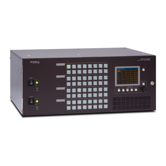
2. Panel Descriptions 2-1. MFR-3000 Front Panel MFR-3000 ROUTING SWITCHER POWER 1 ALARM POWER 2 ALARM Name Description POWER1 Power switch 1 (standard equipment) (1) Switch to turn unit power On/Off. (2) DC power supply voltage indication LED (Normal: lit green / Error: unlit) - Page 12 12-SDI Signal Routing 12G-SDI signal routing is enabled by installing MFR-8SDIGB and MFR-8SDOGB cards and using them for 12G-SDI input/output. (If using MFR-8SDIGB and MFR-8SDOGB them for 3G-SDI input/output, the “Standard SDI Signal Routing” table in the previous page applies.) Matrix size varies depending on the number of installed MFR-8SDIGB and MFR-8SDOGB cards as shown below.
-
Page 13: Mfr-30Fp Front Panel
Button labels can be changed on user-assignable buttons. Utilize button label templates in the FOR-A web site. To remove button caps, use an optional tool. Go to the MFR-RU Series page in the FOR-A site and download the following files: “MFR-16RUW_32RUW_4ChrOneLine.pdf”... -
Page 14: Mfr-3000 Rear Panel
1 2 3 4 5 6 7 8 1 2 3 4 5 6 7 8 Slot No. 01 02 03 04 05 06 07 08 09 10 11 12 13 14 15 16 * The above figure shows an MFR-3000 with MFR-8SDI and MFR-8SDO cards installed. Name Description... -
Page 15: Cooling Fans
Available slot pairs are No. 09-10, 11-12, 13-14, and 15-16. Cooling fans Four cooling fans are installed in MFR-3000 units: FAN 1 and 2 are on the rear panel and FAN 3 and 4 are on the front panel as shown below. -
Page 16: Interfaces
2-3-1. Interfaces SERIAL Connector (9-pin D-sub, male) RS-232C or 422 interface can be selected via the CPU card DIP switches. (See Sec. 2-3-4. "Changing the Interface from RS-422 to RS-232C." 9-pin D-sub, male RS-422 connector pin assignment (Factory default settings) Pin No. - Page 17 ALARM Connector (9-pin D-sub, female) Alarm 1 Out: Under normal operation: Pins 1 and 6 are open. In a malfunction or power-off state: Pins 1 and 6 are closed. Alarm 2 Out: Under normal operation: Pins 2 and 7 are open. In a malfunction or power-off state: Pins 2 and 7 are closed.
-
Page 18: Sdi Input/Output Cards
MFR-3000 units allow Input/Output cards to be installed into slots on the rear panel. Removing input /output cards (1) To remove an installed card while the MFR-3000 power is on, turn OFF the corresponding I/O card power switch (set the switch to down). * (2) Press SET for a second, then remove the card. - Page 19 MFR-30CPU. (4) Connect MFR-LAN2 to the same network as MFR-LAN1. (5) If the power of the MFR-3000 is turned off, turn on the power and wait more than one minute. (6) Turn on the Power switch on the rear of the MFR-30CPU and wait about 5 minutes.
-
Page 20: Changing The Interface From Rs-422 To Rs-232C
IMPORTANT Note that internal switch settings should only be performed by qualified technical personnel. (1) Remove the 6 screws on the MFR-3000 top panel to remove the panel. (2) The MAIN card factory default settings are as shown below. 232C... -
Page 21: Sdi Input / Output Cards
2-4. SDI Input / Output Cards 2-4-1. MFR-8SDI MFR-8SDI is an SDI input card and can accept 8 of 3G/HD/SD-SDI and ASI signals. Up to 8 cards can be installed into Slot No. 01 to 08. ► See Sec. 2-1-1. "Matrix Size Chart." BNC x 8 inputs (3G/HD/SD-SDI or ASI signal auto-detection) Set up input signals in the Web-based Control Software as shown below. -
Page 22: Mfr-16Mv
2-4-3. MFR-16MV MFR-16MV is an SDI output card and can output 16 of 3G/HD/SD-SDI and ASI signals. Up to 4 cards can be installed into Slot No. 09 to 16. Two slots are required for each card. Any outputs (BNC) on the card are available for multiview channels. 3G/HD-SDI signals can be output for multiview output. -
Page 23: Mfr-8Sdogb
Source Assignment In the left side of the Web-based Control screen, click to select [Router System Settings - Source Assignment] in the menu tree to display the settings page.. This page allows you to assign physical inputs to logical input channels. ... -
Page 24: Audio Input / Output Cards
2-5. Audio Input / Output Cards Source and destination assignment procedures for audio signals are the same as those for SDI signals. Refer to the previous chapter. This chapter describes audio specific setup. Audio signals should be setup in the Web-based Control pages ►... -
Page 25: Mfr-8Aao (Analog Output)
Channels 9 to 16 Pin No. Setting Pin No. Setting CH9+ CH9 COM CH9- CH10+ CH10 COM CH10- CH11+ CH11 COM CH11- CH12+ CH12 COM CH12- CH13+ CH13 COM CH13- CH14+ CH14 COM CH14- CH15+ CH15 COM CH15- CH16+ CH16 COM CH16- 2-5-2. - Page 26 Analog Audio Connection For balanced audio signals, connect the hot, cold and shield conductor to "+" ," - " and "COM" pins respectively. For unbalanced audio signals, connect the conductor that carries audio to a "+" pin and ground to "COM." Analog Audio Connector (25-pin D-sub, female, inch screws) x 2 Pin Assignments Channels 1 to 8...
-
Page 27: Mfr-8Aesi (Aes Input)
2-5-3. MFR-8AESI (AES Input). MFR-8AESI is a digital audio input card. Up to 8 cards can be installed into Slot No. 01 to 08. ► See section 2-1-1. "Matrix Size Chart." BNC x 8 inputs (8 stereo pairs, 16 channels), unbalanced, 75 Ohm 2-5-4. -
Page 28: Mfr-Gpi
2-6. MFR-GPI 2-6-1. Front Panel MFR-GPI GPI UNIT SERIAL POWER BUSY GPI 1 RESET Item Description Displays the power status. POWER ► See the table below for details on indications. Displays the flash memory writing status of backup settings. BUSY ►... -
Page 29: Rear Panel
2-6-2. Rear Panel SERIAL SERVICE RATING LABEL MFR-LAN GPI 1 GPI 2 GPI 3 GPI 4 2 -DC12V IN- 1 Item Description Used to connect the MFR main unit MFR-LAN (*1) Ethernet port (10/100BASE-TX) SERVICE Used for maintenance only. Do not use. DC 12 V IN 1 and Used to supply 12 V DC power. -
Page 30: Interfaces (Mfr-Gpi)
2-6-3. Interfaces (MFR-GPI) GPI IN / TALLY OUT Connector (37-pin D-sub, female) Pin No. Signal Pin No. Signal GPI_IN / TALLY_OUT 01 # GPI_IN / TALLY_OUT 20 # GPI_IN / TALLY_OUT 02 # GPI_IN / TALLY_OUT 21 # GPI_IN / TALLY_OUT 03 # GPI_IN / TALLY_OUT 22 # GPI_IN / TALLY_OUT 04 # GPI_IN / TALLY_OUT 23 #... - Page 31 GPI OUT / TALLY OUT Circuit MFR-GPI External device Max. voltage: 40 V Max. current: 100 mA 10Ω * The voltage is about 0.9 V when turned-on.
-
Page 32: Switches On The Card
OFF all connected units / disconnect power cords prior to accessing the interior. Further note that adjustments and maintenance should only be performed by qualified technical personnel familiar with FOR-A equipment. Remove the two screws on both sides of the MFR-GPI to access the internal card as shown below. -
Page 33: Mfr-Talm
2-7. MFR-TALM 2-7-1. Front Panel MFR-TALM TALLY MAN AGER UNIT POWER BUSY REF IN RS-422 RESET Item Description Displays the power status. POWER ► See the table below for details on indications. Displays the flash memory writing status of backup settings. BUSY ►... -
Page 34: Rear Panel
2-7-2. Rear Panel RS-422 DC12V IN PC-LAN MFR-LAN REF IN SER. NO. Item Description Ethernet port for connection to PC or other external unit PC-LAN (10/100BASE-TX, RJ-45) Ethernet port for connection to MFR main unit MFR-LAN (10/100/1000BASE-T, RJ-45) Used to input a reference signal (BB or Tri-level sync signal) REF IN (with loop-through. -
Page 35: System Configuration Example
The block diagram below shows an example of the basic MFR routing system that consists of an MFR-3000, Remote Unit and the Web-based Control accessed from a computer. Make sure to connect both MFR-LANs (CPU1) and (CPU2) to a LAN respectively for CPU redundancy. -
Page 36: Main Unit Linking
3-2. Main Unit Linking The Main Unit Link feature allows you to control multiple MFR-3000 units at the same time. Two types of system configurations are available: Parallel Link: Controls several MFR-3000 units at the same time. Expanded Matrix: Creates an expanded virtual matrix by linking MFR-3000 units. -
Page 37: Expanded Matrix System Example
1) Connect all devices in the MFR system as shown in the figure in the previous page. Power on the MFR-3000 to be set as a Master, Remote Control unit and PC. Set the IP addresses for the Remote Control unit () and PC (). Power off the MFR-3000. -
Page 38: Signal Name And Tally Link System
The block diagram below shows a basic signal name and tally link system. To connect a video switcher via serial connection, use the MFR-3000 SERIAL port or SERIAL1-4 on MFR-GPI. The signal name and tally link system requires an RS-422 interface. - Page 39 The figure below shows the routing of signal name and tally data. Set each serial port following the table on this page using the MFR Web Control and on the switcher. Each tally information setting should be performed in the [Web-based Control:Tally System Settings page]. MFR-3000 Video Switcher (HVS-4000) MFR-8SDI MFR-8SDO Names>>...
-
Page 40: If Configuring An Mfr-Talm
The block diagram below shows an example signal name and tally link system comprised of a FOR-A video switcher and multiviewer using an MFR-TALM unit. The MFR-TALM is specifically designed to perform the task of tally data computation, which is ordinarily undertaken by the MFR main unit, to accelerate the computation. - Page 41 Transmitting Signal Name and Tally Data The figure below shows an example signal name and tally data routing system using the MFR-TALM. MFR-3000 MFR-8SDI MFR-8SDO Video Switcher OUT1 (HVS-4000) RS-422(1) RS-422(4) IN64 OUT64 MFR-LAN PC-LAN Multi Viewer (MV-3200) MFR-TALM...
- Page 42 TCP/IP Setting Open the [MFR-TALM Web-based Control: Port Settings page] and perform port settings under TCP/IP Port. [Port Settings] - [TCP/IP Port] Access Port Menu IP Address Port Function Method Web-based Control TSL UMD protocol (MV TCP/IP Client V5.0 Tally out [TALM Settings] IP address) port number)
-
Page 43: Switcher's Aux Crosspoints Switching System
3-4-1. Switching an AUX Bus Signal Assume that the system is configured as shown below: AUX1 on the switcher is assigned to DST 129 (Level 1) on the MFR-3000. IN1-8 and STL(Still) 3 on the switcher are assigned to SRC129-137 on the MFR-3000. - Page 44 1) Connect and assign video signals as shown in the figure above. 2) Device Setup on the MFR-3000: Connect to the MFR-3000 from the Web-based Control PC and open the [Tally System Settings - Device Select] page. Select HVS-390HS in the [Switcher] field and click [Send].
-
Page 45: Synchronous Crosspoints Switching
Assign IN1 to SRC 129. After above setup settings are complete: If SRC 129 is selected for DST 129 on the MFR-3000, IN1 is selected for AUX1 on the switcher. If SRC 3 is selected for DST 129 on the MFR-3000, IN9 is selected for AUX1 on the switcher and SRC 3 is also selected for DST 61 on the MFR-3000. -
Page 46: Front Panel (Mfr-30Fp) Operation
4. Front Panel (MFR-30FP) Operation 4-1. Functions and Operations The below table shows the functions that can be controlled using the front panel and/or Web-based Control (GUI). * For details on Web-based Control operation, see the separate MFR SERIES Web-based Control Operation Manual. -
Page 47: Basic Operation On The Front Panel
ALA RM Button Assign Procedure (1) In the Web-based Control, click to open the MFR-3000 menu tree at the left side. Click to select 30FP Assign Function to display the menu page. (2) Set the page, button and function respectively to assign functions to buttons. Buttons can be selected by specifying Button IDs or clicking on button icons. - Page 48 Default front panel button groups are determined as shown in the figures below. MF R-30 00 ROU TING SWIT CHER Group A LOCK POW ER 1 Group B CAN CEL BUT TON ALA RM DEST SR C ASSIGN GR OUP SETTING Group C POW ER 2...
-
Page 49: Function Buttons
4-3. Function Buttons Functions are assigned to buttons in the [Web-based Control: 30FP Assign Function page] and available functions are as shown in the below table. Function Description Refer to None No function is assigned. Destination 5-1-1 Allows you to change a destination to the destination specifically assigned to the button. -
Page 50: Operation Using The Menu Display
4-4. Operation Using the Menu Display The front panel allows button function and group assignments as well as destination channel selection and crosspoint change using the menu. Showing / hiding the menu display To hide the menu display from the screen, press and hold CANCEL for five seconds. To display a menu screen, press one of menu buttons below the screen. -
Page 51: Source Menu
4-4-2. Source Menu Pressing SRC opens the Source menu. The current destination channel source is shown highlighted in the source list. To change the destination channel source, turn CONTROL, then press CONTROL. To cancel the operation process, press CANCEL. 4-4-3. Crosspoint Menu Simultaneously press DEST and SRC opens the Crosspoint menu. -
Page 52: Button Assign Menu
4-4-4. Button Assign Menu Pressing BUTTON ASSIGN opens the Button Assign menu. The selected button is shown highlighted green and its function is displayed in the right area. (See the table below for details on function parameter settings.) Function Parameters To change button function: (1) With holding down CONTROL, press a free button on the front panel. -
Page 53: Button Group Menu
4-4-5. Button Group Menu Pressing BUTTON GROUP opens the Button Group menu. The current groupings of free buttons are shown in 5 colors To change a group of a button: (1) Turn CONTROL to select a free button on the screen, then press CONTROL to confirm the selection. -
Page 54: Brightness
4-4-6-1. BRIGHTNESS Parameter Setting range Description MENU 1-16 Sets the menu screen brightness. BUTTON Sets the button brightness. BUTTON LOWLIGHT NORMAL Allows you to select the low right. LOWER 4-4-6-2. MFR-LAN To change an MFR-LAN port settings: (1) Turn CONTROL to select an IP or mask, then press CONTROL. (2) Press CONTROL to select a number to be changed. -
Page 55: Pc-Lan
4-4-6-3. PC-LAN To change the PC-LAN port settings: Refer to the procedure for MFR-LAN in the previous page to change settings. To reboot the PC-LAN port: (1) Turn CONTROL to change REBOOT to YES. (2) Press CONTROL to reboot the PC-LAN port. 4-4-6-4. -
Page 56: Crosspoint Control
5. Crosspoint Control 5-1. One Crosspoint Switching There are two ways of switching crosspoints: Switching a crosspoint one at a time, or switching multiple crosspoints simultaneously. This section describes the switching of one crosspoint. 5-1-1. One Crosspoint Switching by X-Y Setting A crosspoint can be switched by using the destination and source buttons on the front panel. -
Page 57: Chop Function
5-1-3. CHOP Function The CHOP function allows you to alternate 2 images to compare the images. Enabling the CHOP function (1) Press one of 2 source buttons (source A) to compare the images. (2) While holding down the source button, press and release another source button (source Source A and B images alternate. -
Page 58: Simultaneous Crosspoint Switching
Ex. 2: To use the TAKE button assigned to Direct mode Step Description In Direct mode, the Take function is always enabled. Select a crosspoint by selecting a destination button and source button. The selected buttons will blink. * To switch multiple crosspoints, repeat the procedure. After completing the crosspoint selection, press the blinking TAKE button to switch the crosspoint/s. -
Page 59: Front Panel Stored Salvos
5-2-2. Front Panel Stored Salvos This type of salvo allows to you assign crosspoints to be simultaneously switched to a front panel button. Storing Front Panel Salvo Data Front panel salvo data can be stored using the Web-based Control. ►... -
Page 60: Lock
5-3. Lock Function operation and crosspoint changes can be disabled by the Lock function. LOCK Function The Lock function is a function that inhibits the use of function buttons or crosspoint changes. There are three types of Lock functions. Inhibits source channel and function Inhibits operation on own unit... -
Page 61: Lock Other / Lock All
5-3-2. LOCK OTHER / LOCK ALL The Lock Other and Lock All functions disable crosspoint changes for current destination channels to all other units or all units including the unit that enabled the Lock function. Lock functions can be disabled only from the unit that enabled the function. In multi-panel operation, lock functions can be disabled from any remote control panel in the operation system. - Page 62 LOCK GROUP The LOCK OTHER function also enables Group LOCK OTHER, which allows crosspoint switching by RU units only in the same group and locks RU switching in other groups. Any RU in the same group can lock or release the LOCK OTHER command. LOCK ALL disables crosspoint switching from all remote control units and can be unlocked only by remote control units in the same group.
-
Page 63: Preview Function
5-4. Preview Function The preview function allows you to set an output to be used for the preview. (ex.) When pressing a source button on the remote control panel for a simultaneous crosspoint switch, the selected source will be output to the preview output. Then you can check images of the source channels to be assigned to a Take. -
Page 64: Multiview Output
6. Multiview Output The MFR-16MV card allows you to output multiview images using any two BNC connectors, in which up to 16 video windows and two clocks can be displayed on a single or dual multiview screen. Process Block Diagram Any router sources can be used as multiview window sources. -
Page 65: Fs Mode
- Audio level meter (16 channels) - Timecode - Video loss Layout pattern 16 (16 per a single MFR-3000 unit) registers Layout Manager Screen and window layout creation and editing in Web-based Control * Window and text locations are arbitrary. -
Page 66: Displaying Multiview Images
6-3. Displaying Multiview Images At first, select Destination channels used for multiview images in the Web-based Control. (1) Opent the [Web-based Control: Crosspoint Status page]. (2) Press One Touch. (3) Select Destination channels for a multiview image and press MV-OUT1 or MV- OUT2. -
Page 67: Basic Rules For Creating Multiview Layouts
6-4. Basic Rules for Creating Multiview Layouts Three types of windows, 16, 9 and 4, are available. Although windows are shared between MV-OUT1 and MV-OUT2, window duplications are not allowed. For example, if Window 1 is displayed on MV-OUT1, MV-OUT2 cannot display Window1. -
Page 68: Available Window Objects
6-6. Available Window Objects Timecode Window frame 23:59:59:29 Audio level meter Tally marker Label 1 Label 2 Label Label Label 1 and Label 2 can display simultaneously. Label 1 and Label 2 are concatenated. Size: Select from 3 sizes. Label text: Select from Title, Alarm and Title+Alarm. Title: Displays channel names or text specified by DP-ID. -
Page 69: Gearbox Feature (Mfr-8Sdigb/8Sdogb)
Gearbox, A, B and C connectors are disabled. MFR-8SDIGB MFR-8SDOGB 3G-SDI 3G-SDI 3G-SDI 3G-SDI Gearbox 1 Gearbox 1 3G-SDI 3G-SDI 12G/3G-SDI 12G/3G-SDI MFR-3000 routing Gearbox 2 Gearbox 2 Supported formats Signal format Video format Standard 3840 x 2160/59.94p 4:2:2 SMPTE 12G-SDI ST2082-10... -
Page 70: Available Conversions
In the Web GUI, specify the Gearbox input and output formats, and then assign input/output physical channels to logical channels. Use Link Settings that allow simultaneous 4-channel operation and facilitate crosspoint switches. 7-3-1. Converting 3G SQD Input to 2SI (MFR-8SDIGB) MFR-8SDIGB Quad Link Quad Link Gearbox 1 3G-SDI 3G-SDI MFR-3000 (SQD) (2SI) routing... -
Page 71: Converting 2Si To Sqd Output (Mfr-8Sdogb)
3) Use a remote control unit or the Crosspoint page in the Web GUI to assign output channels to SRC1-4. 7-3-2. Converting 2SI to SQD Output (MFR-8SDOGB) MFR-8SDOGB Quad Link Quad Link Gearbox 1 MFR-3000 3G-SDI 3G-SDI (2SI) (SQD) routing 1) Open the Gearbox Settings page in the Web GUI and select signal formats under From and To as shown below for a Gearbox in the MFR-8SDOGB card block. -
Page 72: Converting 12G-Sdi Input To 3G-Sdi 2Si (Mfr-8Sdigb)
7-3-3. Converting 12G-SDI Input to 3G-SDI 2SI (MFR-8SDIGB) MFR-8SDIGB Quad Link Gearbox 1 3G-SDI MFR-3000 (2SI) routing 12G-SDI 1) Open the Gearbox Settings page in the Web GUI and select signal formats under From and To as shown below for a Gearbox in the MFR-8SDIGB card block. (This example sets Gearbox 1 on the Slot 1 card.) - Page 73 7-3-5. Payload ID Adding Payload ID information to Output Signals. Select Payload ID information source for output signals. Insert: Data created for output signals. Through: Data embedded to input signals. Adding 8K Quad-Link Payload ID Information. When converting 3G Quad-Link to 12G-SDI, Payload ID information for 8K Quad-Link (In compliance with SMPTE 2082-1) is able to be added to 12G-SDI output.
- Page 74 7-3-6. 3G-SDI BNC Output Settings When converting 3G Quad-Link to 12G-SDI, 3G-SDI Black or 12G-SDI Link 1 are selectable for remaining 3 SDI output signals.
-
Page 75: Serial / Lan Command Control
Max. 16 Response / Resending Wait before sending next command (Resend if the Echo is not returned.) Login password None Communication protocol TCP/IP, Control PC: Client, MFR-3000: Server Crosspoint Remote Control using ASCII code. Command protocol Crosspoint Remote Control protocol... -
Page 76: Control Command
8-3. Control Command The control command list below shows the standard control commands for Crosspoint remote control and Crosspoint remote control 2 protocols, which are available for both LAN and serial interfaces. Control command list Function Serial LAN *1 Protocol *2 Commands (S?) for requesting the crosspoints list Commands (X?) for requesting information on crosspoints... -
Page 77: Command Responses (Commands 1-6)
@[sp]A? If CPU is active: @[sp]A:<ID> 8-3-4 If CPU is passive: (No response) @[sp]W?<Lvl>,<Dest> W!<Lvl><Dest>,<ID>,0-2* 8-3-5 *0: Nothing locked 1: LOCK ALL 2: LOCK OTHER K:<S or D><S or L or A><No.>,<Dat> 8-3-6 No : Start channel number Dat: Channel names using hex characters (max. - Page 78 “C” responses A “C” response is sent as shown below when a control command is received: [CR][LF]C:<Lvls>/<Dest>,<Src>[…[S<Salvo number>][L<Link number>]]:I<ID>[CR][LF] C responses are sent to all the terminals in the system. C response ON/OFF can be set in [Web-Based Control: Port Settings page. Parameter Setting range Description...
-
Page 79: Receiving Responses (Commands 1-6)
8-3-2. Receiving Responses (Commands 1-6) Timeout Waiting for Command Response from MFR Set the timeout period (maximum permitted time until its response returns from the MFR unit) to 1 second for short message commands and to 5 seconds for long message commands. - Page 80 Response Message Evaluation Example: Response message received New line? [CR] or [LF] Prompt? Is the 1st character of a line Prompt? - Prompts are not added to line buffers. Add to the line buffer Processing S Response Does the line buffer begin with S:? - Other characters are recognized and used as tally.
- Page 81 If Commands are Overlapped: Two or more commands are sent from different terminals (via serial or LAN interface, or Remote Control units), all command results (C and S responses) are sent to all these terminals from the MFR. The following command examples shows how overlapped commands are processed. Ex.) Assume that the following commands are overlapped: Terminal 1 sent “@ X:0/2,4.”...
-
Page 82: Channel Name Request Commands (7)
8-3-3. Channel Name Request Commands (7) K? Commands allow you to obtain Source and Destination names in ASCII and/or in Kanji set in the MFR Web-based Control menu. Up to 32 channel names can be obtained per a single request. Note that the number of request channels exceeds the system maximum size, no data will return for the exceeded channels. - Page 83 Command Example 1: Requesting the Source Channel 1 Ascii Name Web-based Control (Source Name menu) Terminal display Command @ K?SA,000 Response @ K?SA,000 Echo K:SA000,5352432031 Ascii Name for Source Channel 1 is SRC 1. K:SA001,5352432032 Ascii Name for Source Channel 2 is SRC 2. K:SA002,5352432033 Ascii Name for Source Channel 3 is SRC 3.
- Page 84 Command Example 2: Requesting the Destination Channel 101 Kanji Name Web-based Control (Destination Name menu) Terminal display Command @ K?DK,064 Response @ K?DK,064 Echo K:DK064,E587BAE58A9BEFBC91EFBC90EFBC91 Kanji Name for Destination Channel 101 is 出力101. K:DK065,E587BAE58A9BEFBC91EFBC90EFBC92 Kanji Name for Destination Channel 102 is 出力102.
- Page 85 Command Example 3: Requesting the Source Channel 65 Kanji Name Web-based Control (Source Name menu) Terminal display Command @ K?SK,040 Response @ K?SK,040 Echo K:SK040,E382ABE383A1E383A9EFBC91 Kanji Name for Source Channel 65 is カメラ1. K:SK041,E382ABE383A1E383A9EFBC92 Kanji Name for Source Channel 66 is カメラ2.
-
Page 86: Cpu Status Request Command (8)
― バ ― A Source Kanji Channel 72 8-3-4. CPU Status Request Command (8) This command allows you to indicate which CPU is active in the MFR-3000. Command format Control command Command response @[sp]A? @[sp]A:<ID> Control command BYTE No. -
Page 87: Destination Lock Status Request Command (9)
8-3-5. Destination Lock Status Request Command (9) This command (W?) allows you to indicate the destination lock status in the MFR system. Command format Control command Command response @[sp]W?<Lvl>,<Dest> @[sp]W!<Dest>,<ID>, Control command BYTE No. Command [sp] <Lvl> <Dest> CR <Dest>: Destination channel number Command response BYTE No. -
Page 88: Channel Name Import Commands (10)
<Dat> Channel names BYTE9- Strings in Hex characters (max. 128 bytes). Character code: UTF-8 Carriage return 8-3-7. System Size Request Command (11) F? Commands allow you to obtain MFR-3000 system size. Command Format Command Command response @[sp]F?<Lvl> F:<Lvl><Dst Size>,<Src Size>/< Dst Size >,<Src Size>... -
Page 89: Video Format Commands (12)
8-3-8. Video Format Commands (12) Video Format Commands allow you to change router video format. The router restarts automatically when commands are sent out. The commands can also change reference and switching point settings. Command Format Command description Commands Command response Sets video format, @[sp]UF:<YY>/<R#>,<S$>... -
Page 90: Troubleshooting
9. Troubleshooting If any of the following problems occur during operation of your MFR-3000, proceed as indicated below to see if the problem can be corrected before assuming a unit malfunction has occurred. IMPORTANT If the problem cannot be corrected by performing the procedures below, turn the unit off and then on again. -
Page 91: Specifications And Dimensions
10. Specifications and Dimensions 10-1. Unit Specifications 10-1-1. MFR-3000 Video Formats 12G-SDI 2160/59.94p, 2160/50p 3G-SDI 1080/60p, 1080/59.94p, 1080/50p HD-SDI 1080/60i, 1080/59.94i, 1080/50i, 1080/30p, 1080/30PsF, 1080/29.97p, 1080/29.97PsF, 1080/23.98p, 1080/23.98PsF, 1080/25p, 1080/25PsF, 1080/24PsF, 1080/24p, 720/60p, 720/59.94p, 720/50p SD-SDI 525/60, 625/50 Matrix Size Min. - Page 92 Audio Input MFR-8AAI Analog Audio Input Card with A/D converter (Max. 8 cards) - 25-pin D-sub (female) x 2 (8 stereo pairs, 16 channels) - Balanced or unbalanced, 600 ohm or high impedance - Sampling frequency: 48kHz MFR-8AESI AES/EBU Audio Input Card (Max. 8 cards) - BNC x 8 (8 stereo pairs, 16 channels) - 75 ohm, BNC Audio Output...
-
Page 93: Mfr-30Fp
10-1-2. MFR-30FP Buttons/Colors 64 buttons (1 color: green), user assignable Menu display (TFT, 320 x 240) x 1 Menu selection button (1 color: green) x 5 CANCEL button x 1 LOCK control button (1 color: green) x 1 Rotary selector x 1 Temperature 0°C to 40°C Humidity... -
Page 94: External Dimensions
10-2. External Dimensions 10-2-1. MFR-3000 (All dimensions in mm.) MFR-3000 ROUTING SWITCHER POWER 1 ALARM POWER 2 ALARM When an MFR-30FP option installed: MFR-3000 ROUTING SWITCHER LOCK POWER 1 CANCEL BUTTON ALARM DEST ASSIGN GROUP SETTING POWER 2 ALARM... -
Page 95: Mfr-Gpi
10-2-2. MFR-GPI (All dimensions in mm.) -
Page 96: Mfr-Talm
10-2-3. MFR-TALM (All dimensions in mm.) If attaching the rack mount brackets (Dual / Single) - Page 97 Warning This equipment has been tested and found to comply with the limits for a Class A digital device, pursuant to Part 15 of FCC Rules. These limits are designed to provide reasonable protection against harmful interference when the equipment is operated in a commercial environment. This equipment generates, uses, and can radiate radio frequency energy and, if not installed and used in accordance with the instruction manual, may cause harmful interference to radio communications.
- Page 98 2 Executive Drive, Suite 670, Fort Lee Executive Park, Fort Lee, NJ 07024, USA Tel: +1 201 944 1120 Fax: +1 201 944 1132 FOR-A Corporation of America Distribution & Service Center 2400 N.E. Waldo Road, Gainesville, FL 32609, USA Tel: +1 352 371 1505...
Need help?
Do you have a question about the MFR-3000 and is the answer not in the manual?
Questions and answers