
Related Manuals for AMX UDM-1604C


Summary of Contents for AMX UDM-1604C
- Page 1 Operation/Reference Guide UDM-1604C 4x16 Multi-Format Distribution Hub U n i v e r s a l D i s t r i b u t i o n M a t r i x L a s t U p d a t e d : 7 / 1 5 / 2 0 1 0...
- Page 2 AMX is not responsible for products returned without a valid RMA number. AMX is not liable for any damages caused by its products or for the failure of its products to perform. This includes any lost profits, lost savings, incidental damages, or consequential damages.
-
Page 3: Table Of Contents
IR Learning Sensor ....................9 OUTPUT Ports (RJ-45)....................9 UDM Port Pinouts ......................9 UDM Port Transmission Details ..................10 UDM-1604C Rear Panel Components ..............10 Network Port (RJ45) ....................11 Pinout Configuration ..................... 11 Default IP Address ......................11 Serial Port ....................... - Page 4 Connecting a Component Video Input ................15 Connecting an S-Video Input..................16 Cascade IN/OUT Ports .................... 16 IEC Power Connector....................16 Powering the UDM-1604C Hub On ................16 Powering the UDM-1604C Hub Off................16 Wiring and Connections - UDM Receivers ............17 Overview ........................ 17 UDM-RX01 ......................
- Page 5 Table of Contents System Overview ....................23 Configuration ....................25 WebConsole Overview ................... 25 Connecting to the UDM-1604C ................25 Configuration - Status Page ................27 Overview ........................ 27 Port Configuration Options ..................28 Renaming Output Ports....................29 Video Compensation ....................29 Basic Video Compensation....................
- Page 6 Cascading Hubs ....................79 Distributing Video - Using Cascade Kits ..............79 Using Solecis Distribution Amplifiers to Distribute Video ..........80 Distributing Video - Cascading One UDM-1604C Hub ..........82 Distributing Video - Cascading Two UDM-1604C Hubs..........83 CASCADE IN/OUT Connectors ................84 Cascaded Hub Connection Diagrams ................
- Page 7 Upgrading Port Controllers ..................94 Copying the Hub Configuration File ............... 95 Restoring the UDM-1604C Configuration file ............... 96 Loading the Hub Configuration File On the UDM-1604C..........96 Copying Protocols Between UDM Receivers ............96 Retrieving IR Files From the UDM Ports................ 97 Backing up the Hub Configuration File .................
- Page 8 Set Hub Identification ....................115 Get Hub or Port Identification and System Information ..........115 Reset Controller ......................116 Set Protocol......................... 116 Set Port Range ......................116 Status Values ......................116 Ascii / Hex Conversion ..................117 Overview ......................117 UDM-1604C 4x16 Multi-Format Distribution Hub...
-
Page 9: Important Safety Markings
Important Safety Markings Markings Used In This Manual The following symbols are used on the UDM hardware and throughout this Installation Guide to advise you of important instructions. All maintenance must be carried out by an AMX trained and qualified installer. Voltage This symbol () warns the presence of a voltage of sufficient magnitude to cause a severe or fatal electric shock. -
Page 10: Important Instructions
Starting at “0001” and continuing to “9999”. Environmental Conditions The criteria on this page must be observed for the installation of the UDM-1604C. Temperature DO NOT install or operate the UDM Hub in an area where the ambient temperature exceeds 35ºC (95ºF) or falls below 5ºC (35ºF). -
Page 11: Udm-1604C Multi-Format Distribution Hub
The UDM-1604C offers four high-resolution input ports on the back of each unit. Additional Composite video inputs (RJ-45 located on the front) enable the connection of four interconnects from a TVM-1600 Managed TV Distribution Hub or four Composite video sources using approved Video over UTP extenders. -
Page 12: Compatibility
UDM-1604C Multi-Format Distribution Hub Compatibility The UDM-1604C is compatible for use with UDM-RX01 (FG-UDM-RX01) and UDM-RX02 (FG-UDM-RX02) Receivers. Common Mode Sync delivery is supported only on the UDM-RX02. Product Specifications UDM-1604C Specifications Power Requirements: • 90-264V AC, 50/60Hz • Max power consumption: 130W... - Page 13 • UDM-RC10 IR Engineering Remote Control (FG-UDM-RC10) • IR01 IR Emitter Module (FG-IR01) • IR03 External IR Receiver Module (FG-IR03) • Solecis Distribution Amplifiers (see the Solecis Distribution Amplifiers table on page 79 for listing od compatible DAs) UDM-1604C 4x16 Multi-Format Distribution Hub...
- Page 14 UDM-1604C Multi-Format Distribution Hub UDM-1604C 4x16 Multi-Format Distribution Hub...
-
Page 15: Installation
2. Place the UDM-1604C in the Rack and hold steady. 3. Two fixing holes are supplied on each side of the UDM-1604C. Screw the hub into the rack using the fixing holes (FIG. 5). - Page 16 Installation UDM-1604C 4x16 Multi-Format Distribution Hub...
-
Page 17: Wiring And Connections
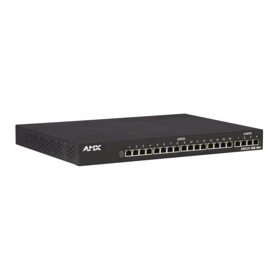
Wiring and Connections Wiring and Connections UDM-1604C Front Panel Components The components on the front panel of the UDM-1604C are described below (FIG. 6). 4 RJ45 Output Ports for IR Learning Sensor connection to TVM Hubs 16 RJ45 Output Ports for connection to UDM-RX01/RX02 Receivers FIG. -
Page 18: Udm Port Transmission Details
No Video 2 NONE No Pb NONE No GREEN LIT NONE NONE UDM-1604C Rear Panel Components FIG. 8 shows the components on the rear panel of the UDM-1604C: Input connections (A - D) Cascade In Cascade Out IEC Power cable connector/switch... -
Page 19: Network Port (Rj45)
The default IP address of the UDM-1604C is 192.168.0.96. Once the UDM-1604C is switched on, use the Setup option in the UDM WebConsole to configure the Hub’s correct IP address (see the Configuration - Setup Page section on page 45). -
Page 20: Serial Port
The Serial port on the UDM-1604is an RJ12 connector, and requires a DB9-to-RJ12 adapter cable (FG-RS01) to connect to a PC for Terminal control. Serial Port - Default Communication Settings Use hyper terminal with default serial settings to communicate with the UDM-1604C (and UDM- RX01): Default Serial Settings... -
Page 21: Irtx (Ir Transmit) Ports
IR commands for each device on the system have to be learned by the UDM-0102 in order to function properly. Refer to the Creating and Learning an IR Protocol section on page 74 on how to learn a device’s IR commands. UDM-1604C 4x16 Multi-Format Distribution Hub... -
Page 22: A/V Source Input Connectors
Wiring and Connections A/V Source Input Connectors There are four sets of input connectors to the rear panel of the UDM-1604C, labelled A, B, C and D (FIG. 12). Digital Audio Input (SPDIF) RCA Audio Inputs (L/R) Video Input (female HD15) FIG. -
Page 23: Video In Connectors (Hd15)
Component video output connectors (Red, Green and Blue). 2. Attach the other end of the cable to the appropriate VIDEO IN connection (A or B) on the UDM. 3. Connect any audio to the analog (RCA) audio connectors or digital (SPDIF) connector. UDM-1604C 4x16 Multi-Format Distribution Hub... -
Page 24: Connecting An S-Video Input
Hub's installation environment. The Power On/Off switch is located beside the IEC power connector. As a Class 1 appliance the UDM-1604C should be connected to a mains supply with a protective earthing connection. Powering the UDM-1604C Hub On 1. -
Page 25: Wiring And Connections - Udm Receivers
• 9600, 8 bit, No Parity, 1 Stop Bit IR Rx Port: 3.5mm stereo input port, for connection of an IR receiver to allow setup of the UDM-RX01, local compensation controls, and remote control of cen- trally located IR devices. UDM-1604C 4x16 Multi-Format Distribution Hub... -
Page 26: Udm-Rx02
UDM-0102 (FG-UDM-0102) - This hub supports Common Synch Mode. UDM-0404 (FG-UDM-0404) - This hub supports Common Synch Mode. UDM-1604C (FG-UDM-1604C) - This hub supports Common Synch Mode. UDM-1604 (FG-UDM-1604) - This hub does not support Common Synch Mode. In this case, the UDM-RX02 will function, but without Common Synch Mode. -
Page 27: Udm-Rx02 Product Specifications
Other AMX Equipment: • RS232 DB9/RJ12 Connection Cable (FG-RS01) • UDM-RC02 Multi-Format IR Remote Control (FG-UDM-RC02) • IR01 IR Emitter Module (FG-IR01) • IR03 External IR Receiver Module (FG-IR03) • UDM-PS 24VDC, 750mA Power Supply (FG-UDM-PS) UDM-1604C 4x16 Multi-Format Distribution Hub... -
Page 28: Udm Receivers - Configuration
(such as DVD player or VCR) can be connected to the UDM Receiver via the IR Tx port, and controlled via the UDM Hub’s WebConsole or via remote control. IR devices controlled via the IRTX ports are typically installed within the same equipment rack as the UDM Hub and Receiver. UDM-1604C 4x16 Multi-Format Distribution Hub... -
Page 29: Connecting An Ir Device To The Ir Tx Port
2. Run the other end of the Component cable to the Component connectors (normally green, blue and red) on the display device. Connect firmly. 3. If appropriate connect audio to the audio connectors on the UDM Receiver. UDM-1604C 4x16 Multi-Format Distribution Hub... -
Page 30: Audio & Video Formats/Resolutions/Distance
Amber – Power (as well as comms if uploading protocols etc. the Amber LED may flicker). While connected receivers may be powered through the UDM Hub, using separate power sources for each receiver is highly recommended, especially with receivers connected to the 15th and 16th ports. UDM-1604C 4x16 Multi-Format Distribution Hub... -
Page 31: Powering On The Udm-Rx02
Audio Out Video Out Audio Out Video In Audio In Video In Audio In UDM Hub Ethernet (network Ethernet UDM Receiver Audio Out Video Out Video In Audio In Display FIG. 18 UDM System Diagram UDM-1604C 4x16 Multi-Format Distribution Hub... - Page 32 Wiring and Connections - UDM Receivers UDM-1604C 4x16 Multi-Format Distribution Hub...
-
Page 33: Configuration
Configuration WebConsole Overview Each UDM-1604C Hub can be configured for the correct network environment. It is also possible to configure each Hub for the correct date and time. Configuration options are available via the UDM’s built-in WebConsole, as described in this section. - Page 34 Configuration After setup you can change TCP/IP address and connect the UDM-1604C to your network equipment (switch, hub, or serial port). Use the links in the left-pane of the page to access each of the main Configuration pages, as described in the following sections.
-
Page 35: Configuration - Status Page
Configuration - Status Page Overview The Status page is the initial view when the UDM-1604C’s WebConsole is accessed. To access the Status page from any other Configuration page in the WebConsole, click on the Status link in the navigation pane (FIG. 20). -
Page 36: Port Configuration Options
Click to select a sync mode for this port. Options include: Common, Auto, On Green, Negative and Positive). By default "Common" sync is selected - in most situations the sync mode should not be changed unless there are sync issue with a particular display device. UDM-1604C 4x16 Multi-Format Distribution Hub... -
Page 37: Renaming Output Ports
3. To add skew delay into any of the video colors, click on the appropriate color hyperlink (FIG. 22). FIG. 22 Skew controls The skew delay cycles through red, green and blue. Each radio button is equivalent to 2ns delay. UDM-1604C 4x16 Multi-Format Distribution Hub... -
Page 38: Advanced Video Compensation
Port Configuration options - with "Enable advanced options" selected in the Setup page 3. In the Cable Distance field, enter the approximate distance of the cable run from the UDM-1604C to the UDM Receiver (in meters). This value is used to automatically adjust the brightness and sharpness of the image. -
Page 39: Video Compensation (Udm-Rx01/Rx02)
1. Ensure the IR03 Endeleo External IR Receiver Module (FG-IR03) is attached to the UDM-RX02 at the IRRX port (FIG. 26). 2. To enter compensation mode, push the ESC and B buttons on the remote control. UDM-1604C 4x16 Multi-Format Distribution Hub... -
Page 40: Dual Output Mode
VGA and Component video. This means at the UDM Receiver, the input could be delivered to two separate display devices. Ensure the correct cabling is in place at the RX to accommodate the 2 separate signals. UDM-1604C 4x16 Multi-Format Distribution Hub... -
Page 41: Selecting Inputs For Display
FIG. 27 Inputs available for a Port "Inputs" mean inputs directly connected to the rear of the UDM-1604C (e.g. Inputs A- D, or devices connected to IRTx ports 1 – 4. 2. Select the appropriate Input which this port will display. - Page 42 Include checkboxes selected for Ports 1-4 (to include Input "A1") The Include All link toggles all the Ports to be included on or off. 3. Click on Execute to configure the ports to display the Included input (FIG. 30). UDM-1604C 4x16 Multi-Format Distribution Hub...
- Page 43 Include column. The blue highlight disappears, and the specified Ports are configured to use the Included input - see FIG. 31). FIG. 31 Ports re-configured to use the "Included" input ("A1") UDM-1604C 4x16 Multi-Format Distribution Hub...
-
Page 44: Changing An Input
The User Control options for a selected port (click the relevant Port’s link to access User Control options). Schedules are also used to issue commands at a pre-determined time to inputs and devices. Refer to the Configuration - Schedule Page section on page 57 for details. UDM-1604C 4x16 Multi-Format Distribution Hub... -
Page 45: Issuing Commands To A Selected Port
Ensure that an (optional) IR01 Endeleo IR Emitter Module (FG-IR01) is connected to the Receiver’s IRTX port. Attach it to the Device’s IR sensor before issuing a command. The IR Emitter transmits the command from the Receiver directly to the device’s IR sensor. UDM-1604C 4x16 Multi-Format Distribution Hub... -
Page 46: Issuing Commands To Multiple Ports
This action invokes the User Control options for the selected Port (FIG. 35). Keys 0 to F represent the keys on the UDM-RC02 Remote Control. Commands for each Key are selected from the Control drop-down menu (provided for each Key). UDM-1604C 4x16 Multi-Format Distribution Hub... - Page 47 3. Open the Control drop-down menu for any Key, and select the command which this key on the UDM-RC02 Remote Control will issue (FIG. 36). Control drop-down for Key 2 FIG. 36 Control drop-down menu for Key 2 UDM-1604C 4x16 Multi-Format Distribution Hub...
-
Page 48: Passthrough Mode (Inputs A-D, Tvm Inputs 1-4)
1. The Device must be added to the system as an Input. 2. IR emitter (on the correct IR port) at the rear of the UDM-1604C must be connected to the device. 3. The Device must be added to the system as a Device and be assigned its learned protocol. -
Page 49: Configuring A Device For Passthrough Mode
3. Click on the Port’s User Control link in the Status page to access the User Control options for the selected port, and click on the Passthrough checkbox for the key dedicated to putting the Receiver into Passthrough Mode (FIG. 40). 4. The device can now be controlled directly at the Receiver end. UDM-1604C 4x16 Multi-Format Distribution Hub... -
Page 50: Passthrough Mode (Inputs Tvm-Av1 - Tvm-Av4)
If a TVM Hub is directly connected to port TVM-AV1 on the UDM Hub and an IR Blaster connected to IR Port 1 (at the rear of the UDM Hub) is associated with Input A, then only channel changes will be permitted on the TVM Hub – i.e. NON Passthrough Mode. UDM-1604C 4x16 Multi-Format Distribution Hub... -
Page 51: Using Passthrough Mode
2. Click on Execute. The port is now locked to that display. Multiple ports can be locked by clicking on the Include checkbox relevant to the port, then clicking on Execute to lock the ports. UDM-1604C 4x16 Multi-Format Distribution Hub... - Page 52 Configuration - Status Page UDM-1604C 4x16 Multi-Format Distribution Hub...
-
Page 53: Configuration - Setup Page
Each Hub must be configured for the correct network environment. It is also possible to view device information, set this UDM-1604C as the Master Hub in a cascaded system, configure the Hub for the correct date and time and specify Restore options, via options in the Setup page (FIG. 42):... -
Page 54: Network Configuration
Configuration - Setup Page Network Configuration The UDM-1604C does not support DHCP. Please configure a static IP Address. The default IP address is: 192.168.0.96 The default UDP Port is: 2008 1. The following Network Configuration options must be configured (FIG. 43): FIG. -
Page 55: Restoring Hub Configuration And Connections
Where appropriate the Hub can be reset from the Browser interface. Use the Setup option to reset the Hub. 1. Click the Reset Hub button (see FIG. 45). The UDM-1604C’s network connection will be lost temporarily and video displays will switch off then on again very quickly. 2. Restart the Hub. - Page 56 Configuration - Setup Page UDM-1604C 4x16 Multi-Format Distribution Hub...
-
Page 57: Configuration - Inputs Page
1. For each Input port (A-D), select the Cascade checkbox, if that input will be cascaded from an upstream UDM-1604C Hub (see the Cascading Hubs section on page 79 for details). 2. For each Input port, select the appropriate input type from the Type drop-down menu provided for each Input (FIG. -
Page 58: Configuring Tvm (Av) Inputs
2. Ensure the power on the TVM port which will transmit the TV feed has been switched off using the [k] [port no] command (or using the TVM’s WebConsole). 3. Connect a Cat5 cable from the TVM port on the front panel of the UDM-1604C (FIG. 49) to the relevant TVM port on the front of the UDM Hub. -
Page 59: Configuring Audio Types For Inputs
FIG. 50 Configuring TVM inputs for a UDM-1604C 5. Configure the default channels for each TVM input. For example if you enter "1" in the text field for TVM-AV1 (as shown in FIG. 50), then every time a UDM user selected TVM-AV1 then they would be initially switched through to TV channel 1. - Page 60 Configuration - Inputs Page UDM-1604C 4x16 Multi-Format Distribution Hub...
-
Page 61: Configuration - Devices Page
The system allows "centrally located" devices connected to the rear of the UDM-1604C (e.g. VCR, DVD, DVR or Satellite Decoders) to be managed from the user port. Centrally located devices are connected directly to the rear of the UDM-1604C via the UDM IR ports (Tx1 – Tx4) using an Endeleo IR Tx bud. -
Page 62: Adding Centrally Located Devices
Refer to the Creating and Learning an IR Protocol section on page 74 for details. Issuing Commands To a Centrally Located IR Device The UDM-1604C needs to learn the device’s IR protocol (which button on its remote performs which function). Refer to the Configuration - Protocols Page section on page 71. -
Page 63: Custom Commands
1. Select the custom option within the 2 list of commands. 2. Type in the value of the IR code which is to be sent in the relevant box. 3. Execute the custom command or schedule it to occur later. UDM-1604C 4x16 Multi-Format Distribution Hub... -
Page 64: Issuing Commands To Centrally Located Devices
Issuing Commands to Centrally Located Devices It is also possible to control centrally located hardware such as DVD players, via options in the Devices page. Remember an IR-TX bud coming from the rear of the UDM-1604C will sit over the Device’s IR sensor. -
Page 65: Configuration - Schedule Page
Configuration - Schedule Page Overview The UDM-1604C features an on-board clock that allows you to create scheduled events to be executed at a predetermined time in the future. Scheduled events are listed on the Schedule page (FIG. 58), but are created using options in both the Status and Devices pages, as described in this section. -
Page 66: Checking The Hub Time
Hub Date and Time Scheduling IR Device Control Events Use the Schedule options in the Devices page (bottom toolbar) to create a scheduled IR Device Control Event (FIG. 60): IR Device Control toolbar FIG. 60 Devices page UDM-1604C 4x16 Multi-Format Distribution Hub... - Page 67 To test the selected commands with the selected Ports, click on the Send To Included link at the bottom of the Devices page (FIG. 63). Note that clicking here sends the commands to the selected Ports, but does not schedule the commands, FIG. 63 Send To Included link UDM-1604C 4x16 Multi-Format Distribution Hub...
- Page 68 7. Click the Add link (see FIG. 66) to add the schedule to the list of scheduled events (FIG. 67). FIG. 67 Scheduled event added 8. Click the event’s Enabled checkbox (FIG. 68). Enabled Scheduled Event FIG. 68 An enabled schedule Once enabled, the scheduled event will execute at the specified time/frequency. UDM-1604C 4x16 Multi-Format Distribution Hub...
-
Page 69: Scheduling Output Device Control Events
1. Select up to two commands to be executed from the 1st and 2nd Control drop-down menus at the bottom of the Status page (FIG. 70). Select command #1 Select command #2 FIG. 70 Commands to be executed UDM-1604C 4x16 Multi-Format Distribution Hub... - Page 70 5. Name the scheduled event in the text field provided. 6. In the Frequency drop-down menu, select a frequency for the scheduled event, and enter the time for the event to occur in the text fields provided (FIG. 74). UDM-1604C 4x16 Multi-Format Distribution Hub...
- Page 71 7. Click the Add link (see FIG. 74) to add the schedule to the list of scheduled events (FIG. 75). FIG. 75 Scheduled event added 8. Click the event’s Enabled checkbox (FIG. 76). Enabled Scheduled Event FIG. 76 An enabled schedule Once enabled, the scheduled event will execute at the specified time/frequency. UDM-1604C 4x16 Multi-Format Distribution Hub...
-
Page 72: Scheduling Inputs
Inputs Control toolbar FIG. 77 Status page 1. In the Status page, select the Inputs to which the schedule will be applied from the Included drop- down menu (FIG. 78). FIG. 78 Included drop-down menu (Status page) UDM-1604C 4x16 Multi-Format Distribution Hub... - Page 73 FIG. 80 Click the top Schedule link to access the Schedule page 4. This invokes the Schedule page. The Input(s) and port(s) selected in the Status page will automatically appear in the scheduled event (FIG. 81). UDM-1604C 4x16 Multi-Format Distribution Hub...
- Page 74 Refer to the Scheduling Events - Frequency Options section on page 68 for a description of each frequency option. 7. Click the Add link (see FIG. 82) to add the schedule to the list of scheduled events (FIG. 83). FIG. 83 Scheduled event added UDM-1604C 4x16 Multi-Format Distribution Hub...
-
Page 75: Preset Scheduling
(in seconds) in the Interval field (FIG. 86). 6. Assign the Preset schedule a unique name by replacing the default text (FIG. 86). 7. Finally click the Add hyperlink button. The Preset event should now appear in the event list. UDM-1604C 4x16 Multi-Format Distribution Hub... -
Page 76: Scheduling Events - Frequency Options
Ensure the relevant schedules have been defined before assigning schedules to the UDM-RC02 Remote Control. 1. In the Status page, click the appropriate Port name hyperlink to access the Port Configuration options shown in FIG. 88: FIG. 88 Port Configuration options UDM-1604C 4x16 Multi-Format Distribution Hub... - Page 77 Control Options page - Schedule drop-down menu Ensure the correct key on the UDM-RC02 Remote Control corresponds with the correct schedule. 4. The Receiver will now accept the relevant command from the UDM-RC02 Remote Control. UDM-1604C 4x16 Multi-Format Distribution Hub...
- Page 78 Configuration - Schedule Page UDM-1604C 4x16 Multi-Format Distribution Hub...
-
Page 79: Configuration - Protocols Page
Protocols for serial and infrared devices used in the system can be created via options in the Protocols page. These protocols allow the UDM-1604C to control serial and infrared devices connected via the Hub. To access the Protocols page from any other Configuration page in the WebConsole, click on the Protocols link in the navigation pane (FIG. -
Page 80: Creating A Serial Protocol
5. Enter the serial command (serial string) equivalent for this action in the Serial command text field. The serial string which reflects the action has to be accurate for the serial command to work. Consult the Manufacturer’s web site or documentation to ascertain the correct string for this serial device. UDM-1604C 4x16 Multi-Format Distribution Hub... -
Page 81: Updating The Udm Receiver With The Serial Protocol
The UDM-RX02 Receiver which will issue the relevant serial commands to the device must be connected to the UDM-1604C’s relevant port (via Cat5/e/6 cable). Once the Serial Protocol and commands have been created, follow these steps to update the connected UDM Receiver with the new protocol: Remember the serial commands are stored within the UDM Receiver. -
Page 82: Creating And Learning An Ir Protocol
UDM Receiver. Creating and Learning an IR Protocol IR protocols can be learned by the UDM-1604C by using the device’s remote control to program its commands into the UDM-1604C. This is performed via options in the Protocols page. -
Page 83: Updating The Udm Receiver With The Ir Protocol
Configuration - Protocols Page Ensure the device’s remote control is pointing to the IR sensor located at the front of the UDM-1604C when performing key presses. If not the key presses may not be stored in the UDM-1604C. 4. Click on Step 1 (FIG. 100). -
Page 84: Testing Serial Control Commands
5. Enter the serial string equivalent to perform the desired control function in the Serial Command text field (see FIG. 102). The UDM-1604C supports a predetermined set of actions (commands), against which you can associate serial strings. For a listing of supported commands, check the Control drop-down menu. -
Page 85: Examples Of Serial Controls
UDM-1604C. See the Ascii / Hex Conversion section on page 117 for details. - Page 86 Configuration - Protocols Page UDM-1604C 4x16 Multi-Format Distribution Hub...
-
Page 87: Cascading Hubs
Cascading Hubs Distributing Video - Using Cascade Kits To ensure that customers are satisfied with the operation of the UDM-1604C even as video resolutions increase, AMX recommends that ALL new installations of the UDM-1604C requiring cascade capability use kit FG1402-61K or kit FG1402-62K as an alternative to the cascade ports built into the UDM-1604C. -
Page 88: Using Solecis Distribution Amplifiers To Distribute Video
VIDEO IN VIDEO IN VIDEO IN VIDEO IN UDM-1604C VIDEO IN VIDEO IN VIDEO IN VIDEO IN UDM-1604C VIDEO IN VIDEO IN VIDEO IN VIDEO IN FIG. 104 Using Solecis Distribution Amplifiers to Distribute Video UDM-1604C 4x16 Multi-Format Distribution Hub... - Page 89 Cascading Hubs FIG. 105 illustrates the video connection layout for a system using four source A/V devices, four Solecis DAs, and four UDM-1604C Hubs (Master Hub plus three Target Hubs): SOURCE 1 SOURCE 2 SOURCE 3 SOURCE 4 AVB-DA-RGBHV-0104 AVB-DA-RGBHV-0104...
-
Page 90: Distributing Video - Cascading One Udm-1604C Hub
Distributing Video - Cascading One UDM-1604C Hub FIG. 106 illustrates an A/V distribution system using two Solecis DAs to distribute video, and one target UDM-1604C Hub to cascade audio to (up to) 32 display devices (16 outputs per UDM-1604C Hub): SOURCE 1... -
Page 91: Distributing Video - Cascading Two Udm-1604C Hubs
Distributing Video - Cascading Two UDM-1604C Hubs FIG. 107 illustrates an A/V distribution system using three Solecis DAs to distribute video, and two target UDM-1604C Hubs to cascade audio to (up to) 48 display devices (16 outputs per UDM-1604C Hub):... -
Page 92: Cascade In/Out Connectors
Cascading Hubs CASCADE IN/OUT Connectors The CASCADE IN and OUT connectors on the UDM-1604C require a UDM-EXP-01 50-Pin Hub Expansion Cable (FG-UDM-EXP01 - not included). The CASCADE IN and OUT connectors on the UDM-1604C are intended to be used for cascading audio only. - Page 93 Cascading Hubs FIG. 109 illustrates an cascaded UDM system with a Master Hub and one target Hub to cascade audio/ video to (up to) 32 display devices (16 outputs per UDM-1604C Hub): SOURCE 1 SOURCE 2 Video Audio Video Audio...
-
Page 94: Configuring The Master Hub
1. In the WebConsole, click on the Setup option. See the Configuration section on page 25 for details on the WebConsole. 2. Click on the Cascade master option (FIG. 111). FIG. 111 Setup page - Cascade Master option UDM-1604C 4x16 Multi-Format Distribution Hub... -
Page 95: Configuring Cascaded Video
4. For each video input (including cascaded video inputs), enter a name in the Name text fields. Renaming the video inputs will make it easier to track which Video Inputs are on each Hub in a cascaded system. UDM-1604C 4x16 Multi-Format Distribution Hub... -
Page 96: Cascading Audio
Master Hub. All downstream UDM Hubs receive audio via the CASCADE Connectors (using the optional 50-pin CASCADE cable - FG-UDM-EXP01). FIG. 113 illustrates connecting audio from 4 source devices to the UDM-1604C: Audio from Source #1 Audio from Source #3... -
Page 97: Configuring Cascaded Audio
In this system there is a Master Hub, and one Target (or "slave") Hub. While the Inputs for UDM-1604C Hubs are physically labelled A, B, C and D on the rear panel, they can be renamed via the Name field in the Inputs page. It is recommended that you rename the ports on the Master and Target Hubs to make it easy to tell which between the ports are on the Master and which the ports are on the Target Hub. - Page 98 Audio Input A cascaded to Input E Audio Input C cascaded to Input G Inputs available to send to RX Receivers: Target Hub CASCADE IN INPUT INPUT INPUT INPUT CASCADE OUT FIG. 117 Two Cascaded Hubs UDM-1604C 4x16 Multi-Format Distribution Hub...
-
Page 99: Example 2 - Cascading Two Hubs
As a result, inputs "J" and "K" on the second Target Hub will present the Cascaded inputs "F" and "C" from the first Target Hub (as opposed to the Local Inputs "I" and "G"), as indicated in FIG. 121: UDM-1604C 4x16 Multi-Format Distribution Hub... - Page 100 Since inputs "A" and "C" on the Master Hub were cascaded to the first Target Hub, and inputs "E" and "H" were cascaded to the second Target Hub, the second Target Hub can distribute Input "C" from the Master Hub. UDM-1604C 4x16 Multi-Format Distribution Hub...
-
Page 101: Advanced Administration
Windows XP Pro has a built in TFTP client program. If you are using another operating system, or have an alternate TFTP client, follow the directions of your OS and install TFTP client if necessary. Consult with AMX Technical Support as to the appropriate client for your OS. -
Page 102: Web Interface Update
Windows XP Pro has a built in TFTP client program. If you are using another operating system, or have an alternate TFTP client, follow the directions of your OS and install TFTP client if necessary. Consult with AMX Technical Support as to the appropriate client for your OS. -
Page 103: Copying The Hub Configuration File
Windows XP Pro has a built in TFTP client program. If you are using another operating system, or have an alternate TFTP client, follow the directions of your OS and install TFTP client if necessary. Consult with AMX Technical Support as to the appropriate client for your OS. -
Page 104: Restoring The Udm-1604C Configuration File
Windows XP Pro has a built in TFTP client program. If you are using another operating system, or have an alternate TFTP client, follow the directions of your OS and install TFTP client if necessary. Consult with AMX Technical Support as to the appropriate client for your OS. -
Page 105: Retrieving Ir Files From The Udm Ports
3. Type in the following command at the prompt, observing the parameters below: TFTP -i [IP address] get ixxxxx.hub or TFTP -i [IP address] get sxxxxx.hub Where ixxxxxx.hub is the name of the Hub configuration file. The file name must start with an i or an s. UDM-1604C 4x16 Multi-Format Distribution Hub... -
Page 106: Restoring The Hub Configuration File
TFTP –i [IP address] PUT u[filename].[portnumber] For example typing in TFTP –i 192.168.0.96 PUT ufilename.001 will upload the Input controller file to Input 1 on the UDM Hub with IP address 192.168.0.96. 4. Push Enter to execute the command. UDM-1604C 4x16 Multi-Format Distribution Hub... -
Page 107: Backend Commands
1. To check the input port configuration, type in the following – a question mark followed by the Input Number (129, 130, 131 or 132): Example: ? 129 2. Push Enter. 3. The following information will be displayed (FIG. 125); FIG. 125 Querying a multi format input port UDM-1604C 4x16 Multi-Format Distribution Hub... -
Page 108: User Outputs
Windows XP Pro has a built in TFTP client program. If you are using another operating system, or have an alternate TFTP client, follow the directions of your OS and install TFTP client if necessary. Consult with AMX Technical Support as to the appropriate client for your OS. -
Page 109: Endeleo Udm Receiver Commands
1. Use Hyperterminal to connect to the Receiver via its serial port. 2. At the command prompt type in setup. 3. Once in setup mode to view the compensation settings, type in z. (FIG. 129) FIG. 129 Video Compensation Settings UDM-1604C 4x16 Multi-Format Distribution Hub... -
Page 110: Resetting Video Compensation Settings
1. Use Hyperterminal to connect to the Receiver via its serial port. 2. At the command prompt type in setup. 3. Once in setup mode type in x to reset the compensation settings if required. UDM-1604C 4x16 Multi-Format Distribution Hub... -
Page 111: Endeleo Ir Codes
Custom 1... through to Custom 10 An asterisk in the Description column for any IR Code in this table indicates that the command will require custom code (since the command is not represented in the Actions list. UDM-1604C 4x16 Multi-Format Distribution Hub... - Page 112 Endeleo IR Codes UDM-1604C 4x16 Multi-Format Distribution Hub...
-
Page 113: Udm Hub Control Protocol
UDM Hub Control Protocol UDM Hub Control Protocol Overview The information in this section applies to UDM-0404, UDM-1604 and UDM-1604C Hubs. The UDM Hub often forms part of a larger system where control of switching and management functions is provided by an external system (for example, AMX or Crestron controllers). -
Page 114: Command Format
UDM Hub Control Protocol For example: BUTTON_EVENT[dvTP,3] // POWER TV PUSH: SEND_STRING UDM,"$C0" // SLIP command wait 2 SEND_STRING UDM,"87,$01,$01,$01,$02,21" wait 4 SEND_STRING UDM, "$C0" // SLIP command The waits used in the example above are not required. By comparison, the equivelant code written for UDP would be: BUTTON_EVENT[dvTP,3] // POWER TV PUSH: SEND_STRING UDM,"87,$01,$01,$01,$02,21"... -
Page 115: Command And Reply Example - Authentication (Login)
UDM Hub Control Protocol The hub replies to all commands, and the reply format are also detailed in this document. For the switching command described above, the reply would be: Byte # Byte value Status Port Input Selected Sub Input Input Type The reply packet starts with the command value, then a Status value (1 for success, other values are listed in section 6.0). -
Page 116: Slip Serial Communication Example
UDM Hub Control Protocol The following example shows SLIP encoding for a UDP packet, showing the start and end characters (192) and substitution of special sequences when the data includes the start and end characters: UDP data SLIP data Responses which are SLIP framed will require decoding at the host. SLIP Serial Communication Example Typically, host systems may not provide support for SLIP encapsulation, so the host must use the normal mechanism for sending serial characters, and add the encapsulation. -
Page 117: Handshaking
UDM Hub Control Protocol Handshaking Although UDP is not deterministic (there is no guarantee that a UDP packet will be delivered), using UDP greatly simplifies the stack processing in the hubs. To accommodate UDP, this protocol requires that the hubs send a completion reply on receipt (and completion) of any command. -
Page 118: Command Summary
UDM Hub Control Protocol Command Summary Command Connect Port Input Disconnect Port Cascade input select Input Cascade value Lock Port Port Unlock port Port Query port 12 X Port Get port or input name 79 X Port Sub port Type Get receiver info 88 X Port... -
Page 119: Disconnect Port
UDM Hub Control Protocol Input type can have the following values: Value Description Composite (CVBS) S-Video Component analog (YPbPr) TV (from TVM) Return Status: Byte # Byte value Status Port Input Selected Sub Input Input Type Disconnect Port Disconnects the current input from the Port specified by the Port property, or if non-zero, from the port specified in the command. -
Page 120: Unlock Port
UDM Hub Control Protocol Unlock Port Unlocks the port (or range of ports) specified by the Port property, or if non zero, the port specified in the command, so that selected inputs on that port may be changed. Byte # Byte value User Defined Port... -
Page 121: Send Remote Command
UDM Hub Control Protocol The parameter block contains at least the following - it may contain extra information, but if not defined here it can be ignored: Byte offset (from 4) Receiver information Receiver type Flags Receiver version number - major Receiver version number - minor Send Remote Command Sends a command to the Rx (which is normally sent on to the screen or other device connected to the Rx). -
Page 122: Send Ir Command To Connected Device
UDM Hub Control Protocol Send IR Command To Connected Device Sends a control command out through the IR blaster or serial port connected to the remote receiver. This is translated in the receiver to the appropriate control protocol previously selected. The receiver must already be loaded with the right driver for the codes used, and the device being controlled must allow the necessary actions. -
Page 123: Get Remote Serial Buffer
UDM Hub Control Protocol Get Remote Serial Buffer Returns the contents of the remote serial buffer. On receiving this command, the remote serial buffer is flushed and characters are acquired until the termination character is received. Once received a reply is sent as below. As a general case, this command would normally be issued before sending a remote serial command to retrieve information from the device connected to the receiver. -
Page 124: Reset Controller
UDM Hub Control Protocol Reset Controller Resets the controller - reboots as though powered on - second 156 (inverted 99) in packet is to guard against accidental resets. Byte # Byte value User Defined User Defined User Defined User Defined Return status: Byte # Byte value... -
Page 125: Ascii / Hex Conversion
(stx) " (etx) (eot) (enq) (ack) & (bel) (bs) (ht) (nl) (vt) (np) (cr) (so) (si) (dle) (dc1) (dc2) (dc3) (dc4) (nak) (syn) (etb) (can) (em) (sub) (esc) (fs) < (gs) (rs) > (us) (del) UDM-1604C 4x16 Multi-Format Distribution Hub... - Page 126 It’s Your World - Take Control™ 3000 RESEARCH DRIVE, RICHARDSON, TX 75082 USA • 800.222.0193 • 469.624.8000 • 469-624-7153 fax • 800.932.6993 technical support • www.amx.com...
Need help?
Do you have a question about the UDM-1604C and is the answer not in the manual?
Questions and answers