Table of Contents
Advertisement
Quick Links
Advertisement
Table of Contents

Related Manuals for AMX UDM-0808-SIG


Summary of Contents for AMX UDM-0808-SIG
- Page 1 Operation/Reference Guide UDM-0808-SIG 8x8 Signature Series Multi-Format Distribution Hub UDM-RX02N Multi-Format Receiver UDM-ABB-8-SIG Signature Series Audio Breakout Box U n i v e r s a l D i s t r i b u t i o n M a t r i x...
- Page 2 AMX is not responsible for products returned without a valid RMA number. AMX is not liable for any damages caused by its products or for the failure of its products to perform. This includes any lost profits, lost savings, incidental damages, or consequential damages.
-
Page 3: Table Of Contents
Environmental Conditions..................b Temperature ........................b Ventilation........................b Humidity.......................... b Water / Liquids........................ b External use ........................b UDM-0808-SIG 8x8 Signature Series Multi-Format Distribution Hub ....1 Overview ........................1 Features........................1 Common Application....................... 1 Compatibility........................1 Product Specifications ..................... 2 Configuration Options .................... - Page 4 "'?SVI'" ............................. 21 "'VI"' ............................22 "'?V'" ............................22 UDM-0808-SIG WebConsole ................23 Overview ........................ 23 Determining the IP Address of the UDM-0808-SIG ..........23 Bonjour (Zero-Configuration) Client ................23 Accessing the WebConsole ................... 24 UDM-0808-SIG, UDM-RX02N and UDM-ABB-8-SIG Operation /Reference Guide...
- Page 5 Clock Manager - NIST Servers ..................33 UDM-0808-SIG Firmware Upgrades ..............35 Overview ........................ 35 Before You Start ..................... 35 Sending a Firmware (*.KIT) File To the UDM-0808-SIG ..........35 Firmware Readme.TXT ....................37 Additional Documentation .................... 37 UDM-RX02N Multi-Format Receiver ..............39 Overview ........................
- Page 6 "'SS'" ............................52 "'?SS'" ............................52 "'CH'" ............................53 "'CP'" ............................53 "'CTOF'" ........................... 53 "'CTON'" ..........................53 "'IROFF'" ..........................53 "'SP'" ............................54 "'XCH'" ............................. 54 "'XCHM'" ..........................54 Serial SEND_STRING....................55 UDM-0808-SIG, UDM-RX02N and UDM-ABB-8-SIG Operation /Reference Guide...
- Page 7 Overview ........................ 71 Common Application..................... 71 Features ........................71 Compatibility......................... 71 Product Specifications ................... 72 Connecting the UDM-ABB-8-SIG to an UDM-0808-SIG........... 72 Connecting Audio Outputs ................... 73 UDM-ABB-8-SIG Configuration ................73 "SFI" Send Command....................73 "SAI" Send Command ....................75 Cascading Hubs ....................77...
- Page 8 Table of Contents Signage Applications..................... 78 Maximizing Performance Of Cascaded UDM-0808-SIG Hubs........79 Configuring a UDM-0808-SIG Hub For Cascading............79 Using the UDM-ABB-8-SIG Audio Breakout Box ............79 Cascading Two Hubs - Cable Connections..............81 Cascading up to Four Hubs - Cable Connections............81 Configuring the Source Hub ...................
-
Page 9: Important Safety Markings
Markings Used In This Manual The following symbols are used on the UDM hardware and throughout this Installation Guide to advise you of important instructions. All maintenance must be carried out by an AMX trained and qualified installer. Voltage This symbol (FIG. 1) warns the presence of a voltage of sufficient magnitude to cause a severe or fatal electric shock. -
Page 10: Important Instructions
Compliance with FCC and IEC standards are found within the rating label; see above. Environmental Conditions The criteria on this page must be observed for the installation of the UDM-0808-SIG. Temperature DO NOT install or operate the UDM Hub in an area where the ambient temperature exceeds 35ºC (95ºF) or falls below 5ºC (35ºF). -
Page 11: Udm-0808-Sig 8X8 Signature Series Multi-Format Distribution Hub
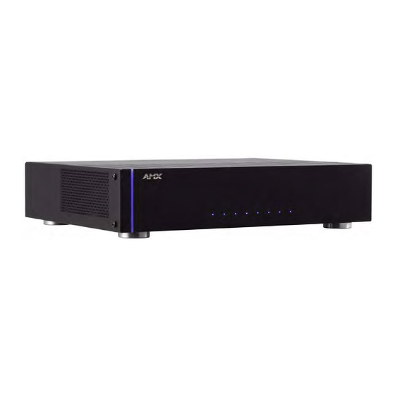
The UDM-0808-SIG Signature Series Multi-Format Distribution Hub (FG1402-01) delivers any video source, including Component, RGB, VGA and S-Video to display devices. The UDM-0808-SIG (FIG. 1) supports 8 high-resolution input ports and 8 UDM output ports, and supports delivery of bidirectional serial and IR to/ from remote devices. -
Page 12: Product Specifications
(1-4 / 5-8): 0808-SIG Hubs. • The Cascade Out ports also provide audio-only to an UDM-ABB-8-SIG Audio Breakout Box. Note: Depending on the application, up to four UDM-0808-SIG Hubs can be cas- caded together. IEC Power Connector: Universal switch-mode power supply. -
Page 13: Configuration Options
UDM-0808-SIG. Remove the aluminum feet from the bottom of the Hub. Attach one rack mounting bracket to each side of the UDM-0808-SIG using two M4 screws for each bracket (FIG. 2). Rack-Mounting Brackets FIG. -
Page 14: Ventilation
UDM-0808-SIG 8x8 Signature Series Multi-Format Distribution Hub Two Mounting holes are located on each side of the UDM-0808-SIG. Screw the Hub into the rack using the Mounting holes (FIG. 3). Mounting holes (2 per side) FIG. 3 Screw the Hub into the rack using the fixing holes DO NOT stand other units directly on top of the Hub when it is rack mounted, as this will place excessive strain on the mounting brackets. -
Page 15: Udm-0808-Sig Wiring And Connections
UDM-0808-SIG Wiring and Connections UDM-0808-SIG Wiring and Connections Overview The system diagram in FIG. 4 illustrates a basic installation using the UDM-0808-SIG Hub, UDM-RX02N receivers, UDM-ABB-8-SIG audio breakout box, and attached display and audio playback devices: Video Projector Screen 1500VG Touch Panel... -
Page 16: Udm-0808-Sig Rear Panel Components
UDM-0808-SIG - Rear Panel Components Connecting UDM-RX02N Receivers to the UDM-0808-SIG Connect a standard Cat 5/5e/6/7cable to a UDM OUTPUT port (1-8) on the UDM-0808-SIG. Connect the other end of the Cat 5/5e/6/7 cable to the “UDM Hub” port on the UDM-RX02N Receiver. -
Page 17: A/V Source Input Connectors
UDM-0808-SIG Wiring and Connections A/V Source Input Connectors There are eight sets of input connectors to the rear panel of the UDM-0808-SIG, labelled A - H (FIG. 7). Digital Audio Input (SPDIF) RCA Audio Inputs (L/R) Video Input (female HD15) FIG. -
Page 18: Connecting A Component Video Input
Attach the other end of the cable to the appropriate VIDEO IN connector (A-H) on the UDM. Connect source audio to the analog (RCA) audio jacks, or digital (SPDIF) Input connector. Video Adapter Cables The following adapter cables are available from AMX, to allow connecting various video input types to the UDM-0102: Video Adapter Cables... -
Page 19: Network Port (Rj45)
FIG. 9 diagrams the pinouts and signals for the Network RJ45 connector and cable. FIG. 9 RJ45 wiring diagram By default, the UDM-0808-SIG is configured for DHCP. Refer to the IP Settings section on page 29 for details. Consult the Network Administrator for correct cabling from the UDM-0808-SIG onto the network. -
Page 20: Serial Port - Default Communication Settings
Not Used CASCADE Ports The CASCADE ports allow UDM-0808-SIG Hubs to be chained together to increase the number of outputs which can be delivered to the end points. The CASCADE IN and OUT connectors on the UDM Hubs require a UDM-EXP-02 Cascade Cable (FG-1402-71 - not included). -
Page 21: Iec Power Connector
Hub's installation environment. The Power On/Off switch is located beside the IEC power connector. As a Class 1 appliance the UDM-0808-SIG should be connected to a wall socket with a protective earthing connection. Powering the UDM-0808-SIG Hub On Ensure a standard PC mains lead has been connected to the 3-pin power connection, and then connected to a mains power source. - Page 22 UDM-0808-SIG Wiring and Connections UDM-0808-SIG, UDM-RX02N and UDM-ABB-8-SIG Operation /Reference Guide...
-
Page 23: Udm-0808-Sig Netlinx Programming
By default, the Device Number assigned to the UDM-0808-SIG is 05600. In NetLinx Studio’s online device tree, the UDM-0808-SIG is listed as a device with a single port, and each UDM-RX02N Receiver connected to the Hub is listed as a separate device immediately following the Hub (FIG. -
Page 24: Levels
UDM-0808-SIG NetLinx Programming For example, if the UDM-0808-SIG is using it’s default device number assignment of 05600, and there are eight UDM-RX02N receivers connected to all eight UDM Output ports on the Hub, then the device numbering would be assigned as follows: ... -
Page 25: Send_Commands
1-8 = Outputs 1-8 - a value of 0 or "ALL" means all outputs Example 1: SEND_COMMAND dvUDM,'"AI4O4,5,6"' Connect input D audio to outputs 4, 5 and 6. Example2: SEND_COMMAND dvUDM,'"A0O1,4,5" Disconnect audio from outputs 1,4 and 5. UDM-0808-SIG, UDM-RX02N and UDM-ABB-8-SIG Operation /Reference Guide... - Page 26 SEND_COMMAND dvUDM,'"CI2O4"' Connect input B video and audio to output 4. Example 2: SEND_COMMAND dvUDM,'"CI3O0" Connect input C video and audio to all outputs. Example 3: SEND_COMMAND dvUDM,'"C0O0"' Disconnect all outputs from inputs. UDM-0808-SIG, UDM-RX02N and UDM-ABB-8-SIG Operation /Reference Guide...
- Page 27 • AO#-II# Where: • O# is the queried output port number • I# is the connected input number (zero if disconnected), for example V4-I2 A4-I2 Indicates that output 4 is connected to input 2. UDM-0808-SIG, UDM-RX02N and UDM-ABB-8-SIG Operation /Reference Guide...
-
Page 28: Mmoff
"'RESET'" Send Command. When changing a Hub from a Target Hub back to a Source Hub, you must send the MMON command, RESET the unit, allow it to come online, then RESET it again. UDM-0808-SIG, UDM-RX02N and UDM-ABB-8-SIG Operation /Reference Guide... -
Page 29: Resetfactory
If RPU is ON, the Hub restores connections and settings internally. If RPU is OFF, the Hub relies on the connected Master to restore status and settings. Returns whether Syntax: RPU is ON or OFF. SEND_COMMAND <DEV>,"'?RPU'" Example: SEND_COMMAND dvUDM,"'?RPU'" UDM-0808-SIG, UDM-RX02N and UDM-ABB-8-SIG Operation /Reference Guide... -
Page 30: Sai
SEND_COMMAND dvUDM,"'SF2FPORT'" through to port 1. Sets expansion channel 2 to be whatever is connected to output port 2 (it follows port 2 as it is switched from one input to another). UDM-0808-SIG, UDM-RX02N and UDM-ABB-8-SIG Operation /Reference Guide... -
Page 31: Sfi
SEND_COMMAND <DEV>, "'?SVI<I#>'" of inputs. Variables: • I# = input number 1-8 = Inputs A-H Example 1: SEND_COMMAND dvUDM,"'?SV2'" Returns configuration of input B. Example 2: SEND_COMMAND dvUDM,"'?SV'" Returns configuration of all inputs. UDM-0808-SIG, UDM-RX02N and UDM-ABB-8-SIG Operation /Reference Guide... - Page 32 The returned string is of the form: VO#-II# Where: • O# is the queried output port number • I# is the connected input number (zero if disconnected) For example V6-I3 Indicates that output 6 is connected to input 3. UDM-0808-SIG, UDM-RX02N and UDM-ABB-8-SIG Operation /Reference Guide...
-
Page 33: Udm-0808-Sig Webconsole
The UDM-0808-SIG is set to DHCP by default. With Bonjour for Windows running on a PC that has access to the LAN that the UDM-0808-SIG resides on, connect the Hub to the network (see the UDM-0808-SIG Wiring and Connections section on page 5). -
Page 34: Accessing The Webconsole
From any PC that has access to the LAN that the UDM-0808-SIG resides on: Open a web browser and type the IP Address of the target UDM-0808-SIG Hub in the Address Bar. Press Enter to access the WebConsole for the specified UDM-0808-SIG Hub. The initial view is the IP Settings page (see FIG. -
Page 35: Udm Control Page
Select Control from the Admin menu to access the UDM Control page (FIG. 17). The options on this page allow commands to be directly entered and replies (notifications) to be displayed for the UDM-0808-SIG hub and connected UDM-RX02N receivers. This page provides a rudimentary control method if there is no master connection. -
Page 36: Device Configuration Page
Device Configuration Page Select Device Configuration from the Admin menu to access the Device Configuration page (FIG. 18). Use this page to view/edit the device configuration for the UDM-0808-SIG. Note that this page consists of two tabs: Device Configuration and Master Connection. -
Page 37: Changing The Connection Mode
Security Settings Select Security Settings from the Admin drop-down menu to open the Security Settings page (FIG. 20). Use the options on the page to specify security options and login information for this UDM-0808-SIG Hub. FIG. 20 Security Settings page... -
Page 38: Enable / Disable Security Settings
Click the Login link in the upper-right corner of the initial page (FIG. 14). This invokes the Login popup page (FIG. 21). FIG. 21 Configuration Manager - Login popup page Enter the default login information: Username = administrator Password = password Click the Login button. UDM-0808-SIG, UDM-RX02N and UDM-ABB-8-SIG Operation /Reference Guide... -
Page 39: Ip Settings
IP Settings Select IP Settings from the Admin drop-down menu to open the IP Settings page (FIG. 22). Use the options on the page to specify network/IP settings for this UDM-0808-SIG. FIG. 22 IP Settings page DHCP: Click to toggle DHCP on this unit (default = enabled). -
Page 40: Port Settings
UDM-0808-SIG WebConsole Port Settings Select Port Settings from the Admin drop-down menu to open the Port Settings page (FIG. 23). Use the options on the page to specify various Port settings for this UDM-0808-SIG. FIG. 23 Port Settings page The options on this page provide inputs for enabling and disabling of HTTP, HTTPS, Telnet, SSH and FTP ports, and allow you to change each port number from it’s standard default assignment. -
Page 41: Clock Manager - Mode Manager
Cancel: Click to exit this page without saving any changes. Click Accept to save your changes. Note that changes on this page take effect immediately. Click Cancel to cancel any changes. UDM-0808-SIG, UDM-RX02N and UDM-ABB-8-SIG Operation /Reference Guide... -
Page 42: Clock Manager - Daylight Savings
(additional fields for Week of the Month, and Day of the Week are provided). Accept: Click to save changes. Changes on this page take effect immediately. Cancel: Click to exit this page without saving any changes. UDM-0808-SIG, UDM-RX02N and UDM-ABB-8-SIG Operation /Reference Guide... -
Page 43: Clock Manager - Nist Servers
To remove a NIST server from the list, click the Remove button. Click Accept to save your changes. Note that changes on this page take effect immediately. Click Cancel to cancel any changes. UDM-0808-SIG, UDM-RX02N and UDM-ABB-8-SIG Operation /Reference Guide... - Page 44 UDM-0808-SIG WebConsole UDM-0808-SIG, UDM-RX02N and UDM-ABB-8-SIG Operation /Reference Guide...
-
Page 45: Udm-0808-Sig Firmware Upgrades
Launch NetLinx Studio and open the Online Device Tree. Sending a Firmware (*.KIT) File To the UDM-0808-SIG Use the Firmware Transfers options in the Tools menu to update the firmware in the UDM-0808-SIG. NetLinx Devices such as the UDM-0808-SIG use KIT files for firmware upgrades. - Page 46 Assuming that the specified target directory contains one or more KIT files, the KIT files in the selected directory are displayed in the Files list box, with the file's last modified date and time (FIG. 31). UDM-0808-SIG, UDM-RX02N and UDM-ABB-8-SIG Operation /Reference Guide...
-
Page 47: Firmware Readme.txt
Send To NetLinx Device dialog (NetLinx Studio) Select the appropriate *.KIT file from the Files list. Enter the Device and System ID numbers for the UDM-0808-SIG in the Device and System text boxes. By default, the Device Number assigned to the UDM-0808-SIG is 05600. - Page 48 UDM-0808-SIG Firmware Upgrades UDM-0808-SIG, UDM-RX02N and UDM-ABB-8-SIG Operation /Reference Guide...
-
Page 49: Udm-Rx02N Multi-Format Receiver
Installed at the display device, the UDM-RX02N (FG1402-20) converts the signal received from UDM-0808- SIG Hubs to standard audio/video signals. In addition, the RX02N supports AMX IR(.irl) files to provide native AMX device control. Serial control of the display device is also possible via standard asynchronous serial support. -
Page 50: Configuration Options
The UDM-RX02N will appear in NetLinx Studio’s Online Device Tree as being connected to the UDM Hub (see Device Numbering section on page 13 for details). By default, the UDM-0808-SIG is assigned device # 05600. By default, the UDM-RX02N is assigned device # 0560X, where X is the port number used by each UDM-RX02N. -
Page 51: Udm-Rx02N Wiring And Connections
The UDM-RX02N is designed to connect to the network via a connection to an UDM Hub. In this document, the UDM-0808-SIG is used as the example, but the UDM-RX02N is compatible with other previous versions of the UDM Hubs. Refer to the relevant UDM Hub documentation (available at www.amx.com) for more information on connecting the UDM-RX02N to other UDM Hubs. -
Page 52: Udm Hub (Rj-45) Port
Audio, Data, Power - Connecting the UDM-RX02N to a UDM-0808-SIG Hub The UDM-0808-SIG Hub features eight UDM OUTPUT RJ45 connectors, each of which support one UDM- RX02N. The UDM-RX02N will then be connected to a display device. UDM OUTPUT Ports 1-8 (RJ45) UDM-0808-SIG (rear panel) FIG. -
Page 53: Control Connectors
UDM-RX02N Wiring and Connections CONTROL Connectors The UDM-RX02N can be controlled via SEND_COMMANDS (UDM-0808-SIG), or via the (optional) UDM-RC05 IR Remote Control (FG-UDM-RC05) The CONTROL connectors on the UDM-RX02N include the SERIAL (RJ12) connector, the IR Rx (IR receive), and IR Tx (IR transmit) ports. -
Page 54: Ir Rx (Ir Receiver) Port
If pass-through mode is required (where an IR-controlled device is controlled via the UDM-RX02N using a an AMX or UDM remote control), then an IR03 External IR Receiver (FG-IR03, not included) is required to receive IR commands from the remote control. Likewise, an IR Receiver is required to compensate video on the UDM-RX02N using the UDM RC05 (Endeleo) remote control. -
Page 55: Using The Udm-Rc05 For Video Compensation
Press EXIT to exit Setup mode Sharpness Gain (Brightness) FIG. 41 UDM-RC05 IR Remote Control - Video Compensation buttons Enter setup mode - press AMX, then MENU Exit setup mode - EXIT Red skew increase - RED ... -
Page 56: Audio & Video Output Connectors
S-VIDEO Output Port FIG. 46 UDM-RX02N - S-VIDEO Port FIG. 47 describes the pinouts on the S-VIDEO connector: S-Video Pinouts Input Pin Ground Y Ground C Chrominance (Color) Luminance (Intensity) FIG. 47 S-Video Pinouts UDM-0808-SIG, UDM-RX02N and UDM-ABB-8-SIG Operation /Reference Guide... -
Page 57: Vga Video Output Port
Run the other end of the Component cable to the Component connectors on the display device and make sure of a firm connection. If the display device has audio feeds, connect its audio to the audio connectors on the UDM-RX02N. UDM-0808-SIG, UDM-RX02N and UDM-ABB-8-SIG Operation /Reference Guide... -
Page 58: Video Compensation
Video Compensation Video can be compensated at the UDM-RX02N using two methods: Via the UDM-0808-SIG, using the NetLinx LEVEL Commands listed in the LEVELs section on page 50. Via the included UDM-RC05 UDM Remote Control - see the Using the UDM-RC05 for Video Compensation section on page 69 for details. -
Page 59: Udm-Rx02N Netlinx Programming
Serial SEND_COMMANDs are described on page 55. Device Numbering In NetLinx Studio’s online device tree, the UDM-0808-SIG is listed as a device with a single port, and each UDM-RX02N receiver connected to the Hub is listed as a separate device immediately following the Hub (the default device number for the UDM-0808-SIG is 05600 - refer to the Device Numbering section on page 13 for details). -
Page 60: Channels
• MIOR1 - AMX R1 remote In all the above cases, the push and release codes are endeleo codes. • MIO - AMX R1 remote - this setting uses all 255 push/release codes. UDM-0808-SIG, UDM-RX02N and UDM-ABB-8-SIG Operation /Reference Guide... -
Page 61: Skb
Variables: channel. • G# = skew value (delay in 2nS intervals) 0-31 = skew value Example: SEND_COMMAND dvRX1,"'SKG17'" Sets the green skew value to 17 (adds 34nS delay to green video). UDM-0808-SIG, UDM-RX02N and UDM-ABB-8-SIG Operation /Reference Guide... -
Page 62: Ir Send_Commands
Stops transmitting IR carrier signals to the IR port. received. "'CARON'" Syntax: Enable the IR SEND_COMMAND <DEV>,"'CARON'" carrier signals Example: (default). SEND_COMMAND dvRXIR,"'CARON'" Starts transmitting IR carrier signals to the IR port. UDM-0808-SIG, UDM-RX02N and UDM-ABB-8-SIG Operation /Reference Guide... -
Page 63: Ctof
Halt and Clear all active or buffered IR commands being output on the designated port. Syntax: Halt and Clear all active or buffered SEND_COMMAND <DEV>,"'IROFF'" IR commands. Example: SEND_COMMAND dvRXIR,"'IROFF'" Immediately halts and clears all IR output signals on the IR port. UDM-0808-SIG, UDM-RX02N and UDM-ABB-8-SIG Operation /Reference Guide... -
Page 64: Xch
SEND_COMMAND dvRXIR,"'XCH 343'" Transmits the IR code as 100-100-100-4-3. Mode 4 Example: • Mode 4 sends the same sequences as the 'CH' command. • Only use Mode 4 with channels 0 - 199. UDM-0808-SIG, UDM-RX02N and UDM-ABB-8-SIG Operation /Reference Guide... -
Page 65: Serial Send_String
Clears all characters in the Rx serial port receive buffer waiting to be sent to the Master. "'RXOFF'" Syntax: SEND_COMMAND <DEV>,"'RXOFF'" Disable the transmission of incoming received Example: characters to the Master SEND_COMMAND dvRXRS232,"'RXOFF'" (default). Stops the Rx serial device from transmitting received characters to the Master. UDM-0808-SIG, UDM-RX02N and UDM-ABB-8-SIG Operation /Reference Guide... -
Page 66: Serial Control Considerations With Udm-0808 And Udm-Rx02N
UDM Hub. Most display devices use simple non-verbose protocol with limited and simple feedback functionality. As such, the RX02N is ideal for one-way serial control (or IR control) of most display devices. UDM-0808-SIG, UDM-RX02N and UDM-ABB-8-SIG Operation /Reference Guide... - Page 67 However, the next command should not be sent until the previous reply has been received in order to avoid Rx data loss. 232 traffic considerations above apply to UDM-0808 and other AMX devices which incorporate RX02N cat5 receivers such as DVX series.
- Page 68 UDM-RX02N NetLinx Programming UDM-0808-SIG, UDM-RX02N and UDM-ABB-8-SIG Operation /Reference Guide...
-
Page 69: Udm-Rx02N Firmware Upgrades
Verify you have the latest version of NetLinx Studio on your PC. Use the Web Update option in NetLinx Studio’s Help menu to obtain the latest version. Alternatively, go to www.amx.com and login as a Dealer to download the latest version. - Page 70 Assuming that the specified target directory contains one or more KIT files, the KIT files in the selected directory are displayed in the Files list box, with the file's last modified date and time (FIG. 54). UDM-0808-SIG, UDM-RX02N and UDM-ABB-8-SIG Operation /Reference Guide...
-
Page 71: Additional Documentation
FIG. 54 Send To NetLinx Device dialog (NetLinx Studio) Select the appropriate *.KIT file from the Files list. Enter the Device and System ID numbers for the host UDM-0808-SIG in the Device and System text boxes. During the upgrade process, the left most front panel LED(s) will blink, and the device stays offline. - Page 72 UDM-RX02N Firmware Upgrades UDM-0808-SIG, UDM-RX02N and UDM-ABB-8-SIG Operation /Reference Guide...
-
Page 73: Udm-Rx02N Ir File Transfers
In the case of UDM-RX02Ns, IRL files are transferred to the RX02Ns, via the UDM-0808-SIG Hub. FIG. 12 on page 13 shows how the UDM-0808-SIG and connected RX02Ns appear in NetLinx Studio’s online device tree (see the UDM-0808-SIG NetLinx Programming section on page 13 for details). - Page 74 Use the Online Device Tree to determine the device's assigned ID, if it has been changed. At this point, the selected IR File and it’s mapping information is indicated in the File list (FIG. 58): UDM-0808-SIG, UDM-RX02N and UDM-ABB-8-SIG Operation /Reference Guide...
-
Page 75: Additional Documentation
File Transfer dialog (NetLinx Studio) Click Send to transfer the file. If the Host UDM-0808-SIG Hub has Firmware version v0.70 or higher, the Hub does not have to be rebooted before the IR file transfers. If the Host UDM-0808-SIG has a Firmware version v0.55, the Hub must be rebooted. When the UDM-0808-SIG is rebooted, it will transfer IRL files to the target RX02Ns. - Page 76 UDM-RX02N IR File Transfers UDM-0808-SIG, UDM-RX02N and UDM-ABB-8-SIG Operation /Reference Guide...
-
Page 77: Udm-Rc05 Multi-Format Ir Remote Control
UDM-RC05 Multi-Format IR Remote Control UDM-RC05 Multi-Format IR Remote Control Overview The UDM-0808-SIG comes with one UDM-RC05 Multi-Format IR Remote Control (FG1402-70). IR Codes / UDM-RC05 Pushbuttons FIG. 60 provides the IR Codes associated with each pushbutton on the UDM-RC05. - Page 78 Nav Down Sky or Endeleo use Nav Left Sky or Endeleo use Nav Right Sky or Endeleo use Exit Sky/DirecTV or Endeleo use I Information/Info Sky/DirecTV Help Text Box Office/List Sky/DirecTV Guide Sky/DirecTV UDM-0808-SIG, UDM-RX02N and UDM-ABB-8-SIG Operation /Reference Guide...
-
Page 79: Using The Udm-Rc05 For Video Compensation
The UDM-RC05 can also be used with UDM-RX02N receivers for video compensation (FIG. 61): In order to use the UDM-RC05 to compensate video on the UDM-RX02N, the RX02N must be set to the AMX remote, via the "RP" command described on page 50. ... - Page 80 UDM-RC05 Multi-Format IR Remote Control UDM-0808-SIG, UDM-RX02N and UDM-ABB-8-SIG Operation /Reference Guide...
-
Page 81: Udm-Abb-8-Sig Audio Breakout Box
The UDM-ABB-8-SIG Audio Breakout Box (FG1402-60) delivers analog and digital audio, buffered and cascaded from the output side of an upstream UDM-0808-SIG Hub. The Audio Breakout Box (ABB) allows up to eight individual audio streams to be centrally delivered as inputs into distributed audio systems that may co-exist with the RX02N receivers. -
Page 82: Product Specifications
Power Status bar: Blue light bar on front panel indicates unit is powered. Rear Panel Components: Audio In Connections: 2 SCSI ports support audio input from the Cascade Out ports on an UDM-0808-SIG Hub. Audio Outputs: • Black RCA female connector - Digital audio (SPDIF) •... -
Page 83: Connecting Audio Outputs
Refer to the UDM-0808-SIG NetLinx Programming section on page 13 for a listing of all Send Commands supported by the UDM-0808-SIG. "SFI" Send Command Use the "SFI" Send Command (on the source UDM-0808-SIG Hub) to specify whether the cascaded audio output on the source Hub will follow either: ... - Page 84 This option allows you to cascade audio from source devices beyond those that are ABB Output 3 physically connected to the UDM Hub. ABB Output 4 FIG. 65 "SFI" Send Command - INPUT & PORT Selectors UDM-0808-SIG, UDM-RX02N and UDM-ABB-8-SIG Operation /Reference Guide...
-
Page 85: Sai" Send Command
Use the "SAI" Send Command to configure a specific audio input to accept signals of a certain type, and set the source as either a local source (devices connected directly to the inputs A-H on the UDM Hub to which the ABB is connected) or cascaded from an upstream UDM-0808-SIG Hub. Syntax: SEND_COMMAND <DEV>, "'SAI<I#>T<T#>C<C#>'"... - Page 86 UDM-ABB-8-SIG Audio Breakout Box UDM-0808-SIG, UDM-RX02N and UDM-ABB-8-SIG Operation /Reference Guide...
-
Page 87: Cascading Hubs
UDM-ABB-8-SIG Audio Breakout Box. The UDM-0808-SIG supports up to eight inputs (A-H), and up to eight outputs (UDM Ports 1-8). Adding up to three more UDM-0808-SIG Hubs is possible via the two sets of CASCADE ports (In/Out 1-4, In/Out 5-8), and optional UDM Cascade Cables (FG-1402-71). -
Page 88: Cascading Guidelines
Maximum Number of Cascaded 0808 Hubs Due to the analog nature of the UDM-0808-SIG, the cascade limits of the product depend on how it is used. As a general rule, AMX recommends limiting the number of cascaded units to 3, unless the system is being used in a signage application or with 4 or fewer inputs. -
Page 89: Maximizing Performance Of Cascaded Udm-0808-Sig Hubs
UDM-ABB-8-SIG Audio Breakout Box below). On an UDM-0808-SIG that has signals cascaded into it, you can choose the cascade input using the SVI (see page 21) and SAI (see page 20) SEND COMMANDs. If you append 'CASCADE' to the end of those commands, the UDM-0808-SIG will use the cascaded input in place of the local input. - Page 90 UDM-ABB-8-SIG Audio Breakout Box Configuration 2 In the example shown in FIG. 70: The UDM-0808-SIG has been commanded to route Source 1 to Outputs 1 through 3. The audio outputs on the Audio Breakout Box automatically reflect this change so that the audio will be sent through the distribution amplifier to the appropriate locations.
-
Page 91: Cascading Two Hubs - Cable Connections
Attach one end of the UDM Cascade cable to a CASCADE OUT port on Target Hub #2 (1-4, 5-8, or both). Attach the other end of the UDM Cascade cable to the matching CASCADE IN port on Target Hub #3.. UDM-0808-SIG, UDM-RX02N and UDM-ABB-8-SIG Operation /Reference Guide... -
Page 92: Configuring The Source Hub
Four cascaded UDM-0808-SIG Hubs Configuring the Source Hub In a cascaded Hub installation, the first UDM-0808-SIG Hub in the chain must be configured as the "Source" Hub. Subsequent downstream Hubs must in turn be configured as "Target" hubs, and should follow a top (Source) to bottom (Target #1, Target #2, Target #3) configuration. -
Page 93: Configuring The Hub As A Target Hub
Use the "SVI" Send Command to configure a specific video input to accept signals of a certain type, and set the source as either a local source (connected directly to the UDM-0808-SIG Inputs A-H) or cascaded from an upstream UDM-0808-SIG Hub. -
Page 94: Cascading Hubs - Code Examples
Sets Input A to VGA / Cascaded. Example 3: SEND_COMMAND dvUDM,"'SVI2TCOMPC'" Sets Input B to Comp / Cascaded. Refer to the UDM-0808-SIG NetLinx Programming section on page 13 for a listing of all Send Commands supported by the UDM-0808-SIG. Cascading Hubs - Code Examples BUTTON_EVENT[TP,1]... -
Page 95: Appendix
(etx) (eot) (enq) (ack) & (bel) (bs) (ht) (nl) (vt) (np) (cr) (so) (si) (dle) (dc1) (dc2) (dc3) (dc4) (nak) (syn) (etb) (can) (em) (sub) (esc) (fs) < (gs) (rs) > (us) (del) UDM-0808-SIG, UDM-RX02N and UDM-ABB-8-SIG Operation /Reference Guide... - Page 96 It’s Your World - Take Control™ 3000 RESEARCH DRIVE, RICHARDSON, TX 75082 USA • 800.222.0193 • 469.624.8000 • 469-624-7153 fax • 800.932.6993 technical support • www.amx.com...
Need help?
Do you have a question about the UDM-0808-SIG and is the answer not in the manual?
Questions and answers