AMX UDM-0102 Instruction Manual
Multi-format distribution hub and receiver
Hide thumbs
Also See for UDM-0102:
- Quick start manual (2 pages) ,
- Operation/reference manual (82 pages) ,
- Operation/reference manual (108 pages)

Related Manuals for AMX UDM-0102


Summary of Contents for AMX UDM-0102
- Page 1 INSTRUCTION MANUAL UDM-0102 & UDM-RX02 M U L T I - FO R M A T D I ST R I B U T I O N H U B A N D R E CE I VE R...
- Page 2 COPYRIGHT NOTICE AMX© 2017, all rights reserved. No part of this publication may be reproduced, stored in a retrieval system, or transmitted, in any form or by any means, electronic, mechanical, photocopying, recording, or otherwise, without the prior written permission of AMX. Copyright protection claimed extends to AMX hardware and software and includes all forms and matters copyrightable material and information now allowed by statutory or judicial law or herein after granted, including without limitation, material generated from the software programs which are displayed on the screen such as icons, screen display looks, etc.
-
Page 3: Important Safety Markings
This symbol (FIG. 3) used within this manual, indicates an important instruction for the correct and safe installation, operation or maintenance of your UDM-0102 and UDM-RX02. Failure to comply with such instruction may result in injury to person or damage to the UDM hardware. -
Page 4: Compliance
DO NOT install or operate the UDM-0102 or UDM-RX02 in an area in which the ambient relative humidity exceeds 85% or an area that is prone to condensation. Water / Liquids DO NOT install or operate the UDM-0102 or UDM-RX02 near water or in a location which may be prone to water seepage, dripping or splashing. -
Page 5: Table Of Contents
SELECT Pushbutton........................ 13 PRESETS 1/2 Pushbuttons...................... 14 UDM Port (RJ45) ........................14 UDM Port Pinouts ..........................14 Connecting the UDM-RX02 Receiver to the UDM-0102............. 14 UDM HUB Port LEDs ....................... 15 UDM-0102 Rear Panel Components ................. 15 A/V Source Input Connectors....................15 VIDEO IN Connectors (HD15)...................... - Page 6 VIDEO Outputs ........................21 Configuration ....................22 WebConsole Overview ..................... 22 Connecting to the UDM-0102.................... 22 UDM-0102 Configuration - Status Page ............23 Overview .......................... 23 Status Page Options ......................23 Port Configuration Options ..................... 24 Selecting a Remote Control Type ...................... 24 Renaming the Output Port .........................
- Page 7 Updating the UDM-RX02 Receiver With the Serial Protocol ........... 49 Creating and Learning an IR Protocol..................50 Creating an IR Protocol ........................50 IR Learning With a Device?s Remote Control ..................51 Updating the UDM-RX02 With the IR Protocol................. 52 Deleting Protocols ........................52 UDM-0102 & UDM-RX02 Instruction Manual...
- Page 8 Determining the Current Firmware Versions ..............53 Downloading New Firmware from www.amx.com ............53 Establishing a TFTP Session with the Hub and/or Receiver ..........54 Upgrading Firmware and Web Pages On a UDM-0102............55 Upgrading Port Controllers ..................... 55 Advanced Administration ................. 57 Overview ..........................
- Page 9 Enable/Disable Remote Key Messages................... 74 Set Hub Identification ......................75 Get Hub or Port Identification and System Information ............75 Reset Controller ........................75 Status Values ........................76 ASCII / Hex Conversion ..................77 Overview .......................... 77 UDM-0102 & UDM-RX02 Instruction Manual...
-
Page 10: Udm-0102 1X2 Multi-Format Distribution Hub
A Serial connection is also provided for CLI administration and diagnostic purposes. The UDM-0102 can deliver all content and control up to 2,300 feet. See the Audio & Video Formats/Resolutions/ Distance section on page 8 for tested and confirmed distances. -
Page 11: Udm-0102 Wiring And Connections
• IR01 IR Emitter Module (FG-IR01) • IR03 External IR Receiver Module (FG-IR03) UDM-0102 Wiring and Connections The system diagram in FIG. 6 illustrates a basic installation using the UDM-0102 Hub, UDM-RX02 receivers, and attached display and audio playback devices: UDM-RX02... -
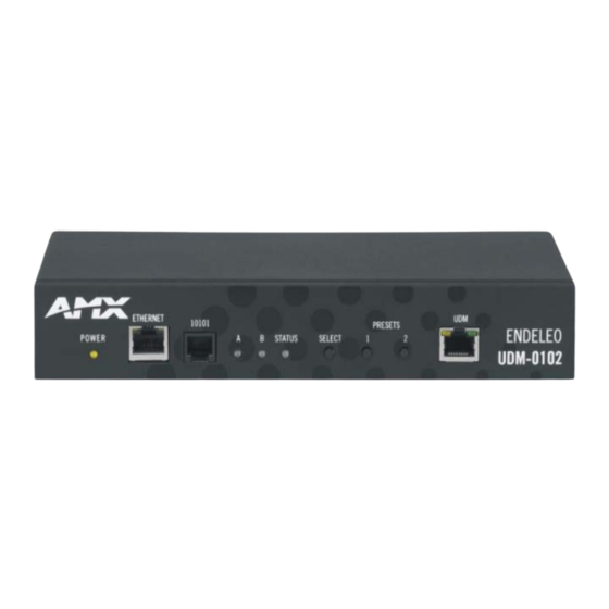
Page 12: Udm-0102 Front Panel Components
Default IP Address The default IP address of the UDM-0102 is 192.168.0.96. Once the UDM-0102 is switched on, use the Setup option in the UDM WebConsole to configure the Hub’s correct IP address (see the Network Configuration section on page 33). -
Page 13: Serial (Rj12) Port
Serial (RJ12) Port The SERIAL (RJ12) port on the front panel (labeled “10101”) is available for diagnostic and troubleshooting purposes. The Serial port on the UDM-0102 requires a DB9-to-RJ12 adapter cable (FG-RS01 included) to connect to a PC for Terminal control. -
Page 14: Presets 1/2 Pushbuttons
Always OFF Connecting the UDM-RX02 Receiver to the UDM-0102 The RJ45 port on the front panel of the UDM-0102 Hub labeled “UDM” supports one UDM-RX02 Receiver. The UDM-RX02 is then be connected to a display device (FIG. 7). Cat5/5e/6 cable FIG. -
Page 15: Udm Hub Port Leds
RCA cable, and an RCA cable cannot be used in its place (the Y, Pb, and Pr connections are shifted from the VESA standard). If a standard cable is to be used, you will have to swap the connectors. Contact AMX Technical Support for details. -
Page 16: Connecting A Component Video Input
Component video output connectors (Red, Green and Blue). Attach the other end of the cable to the appropriate VIDEO IN connection (A or B) on the UDM-0102. Connect any audio to the appropriate analog (RCA) audio connectors or digital (SPDIF) connector (A or B). -
Page 17: Irtx 1 & 2 (Ir Transmit) Ports
50 Use two IR01 IR Emitter Modules (FG-IR01 - not included) to connect the IRTX 1 & 2 ports on the UDM-0102 to the IR receivers on the devices, to allow them to receive IR control signals directly from the UDM-0102. -
Page 18: Udm-Rx02 Multi-Format Receiver
UDM-RX02 Multi-Format Receiver Overview Installed at the display device, the UDM-RX02 converts the signal received from the UDM-1604 or UDM-0102 Multi-Format Distribution Hub to standard audio/video signals. With intelligent receiver technology, each UDM-RX02 is powered remotely from the Multi-Format Distribution Hub via Cat 5/5e/6 cable. The receiver supports an embedded control function to allow detection of a change in signal from the hub and automatic switch of the Plasma or LCD screen to its new video format. -
Page 19: Udm-Rx02 Wiring And Connections
NOTE: Disconnecting the UDM-PS power supply will not power down the UDM-RX02 if the Ethernet connection to the UDM-0102 is intact. To connect the UDM-PS power supply to an UDM-RX02N that is currently connected to a UDM-0102 (via the UDM port): Disconnect the CAT5/5e/6 cable from the UDM HUB port to power the unit down Connect the UDM-PS power supply and reconnect the CAT5/5e/6 cable to the UDM HUB port. -
Page 20: Serial (Rj12) Port
The UDM-RX02 is now capable of issuing IR commands to the display device. IR commands for each device on the system have to be learned by the UDM-0102 in order to function properly. Refer to the Creating and Learning an IR Protocol section on page 50 for instructions on learning a device’s IR commands. -
Page 21: Audio Outputs
Video or Component) on the UDM-RX02. Run the other end of the cable to a video input connector on the display device; connect firmly. Connect any audio to the appropriate analog (RCA) audio connectors or digital (SPDIF) connector. UDM-0102 & UDM-RX02 Instruction Manual... -
Page 22: Configuration
Use the links in the left-pane of the page to access each of the main Configuration pages, as described in the following sections. For the initial setup, you will probably need to visit the Setup page first, to establish network settings for the UDM-0102 (see the Configuration - Setup Page section on page 32). -
Page 23: Udm-0102 Configuration - Status Page
Status Page Options Status Page Options Port • Port 1: Click this link to access the Port Configuration options for the UDM-0102’s input port. See the Port Configuration Options section on page 24 for information. Input • Input (Device) “Input” refers to devices connected directly to the UDM Hub (Inputs A-B). Select an input device to display drop-down menu: from this drop-down menu. -
Page 24: Port Configuration Options
Click on Port 1 link on the Status page (FIG. 22) to access the Port Configuration page. FIG. 22 Port 1 Link on the Status Page The options on the Port Configuration page (FIG. 23) allow you to configure various options for the UDM-0102’s output port. FIG. 23... -
Page 25: Renaming The Output Port
Protocols for Serial and IR devices used in the system can be created via options in the Protocols page (see the Configuration - Protocols Page section on page 44). These protocols allow the UDM-0102 to control connected serial and IR devices. -
Page 26: Input Options
UDM-0102 Configuration - Status Page Dual Output enabled for this Port FIG. 27 Port Configuration Options page - Dual Output enabled for a selected port NOTE: Ensure the correct cabling is in place at the UDM-RX02 to accommodate the 2 separate signals. -
Page 27: Defining User Control
UDM-0102 Configuration - Status Page The blue row at the top of the Schedule page represents the new scheduled event - in this case, a scheduled Connect. The options in this row (from left to right) are: Scheduled Event name text box - this editable field indicates the default name for the new scheduled event, in this ... - Page 28 UDM-RC02 remote control (or SKY or SKY+ remotes) to be used to control devices connected to the UDM-0102 (see the Passthrough Mode section on page 29 for details). Open the Control drop-down menu for any Key, and select the command which this key on the UDM-RC02 Remote Control will issue (FIG.
-
Page 29: Passthrough Mode
The following steps must be taken in order for Passthrough Mode to function correctly: Use an IR01 IR Emitter Module connected to connect an IRTX port on the UDM-0102 to the IR Receiver on the Input Device - see the Connecting an IR-Controlled Device to an IRTX Port section on page 8. -
Page 30: Control Options
UDM-0102 Configuration - Status Page Control Options Administrators can issue IR commands directly from the UDM WebConsole, via the Control options on the Status page. NOTE: Ensure the device’s IR commands have been learned by the Hub first. Refer to the Creating and Learning an IR Protocol section on page 50 for details. - Page 31 UDM-0102 Configuration - Status Page Selected command Selected Click to add this scheduled (Pwr On) Output Port control to the Schedule page Command name Select frequency for (default = "Control") this scheduled control FIG. 39 Schedule Page - command added from Status page (via Schedule control) The default name for the schedule is “Control”, but it can be edited in the text field.
-
Page 32: Configuration - Setup Page
Enter the current time in this set of text fields, in 24-hour format. Click the Set Time link to update the time setting. Restore Options • Restore configuration Select this option to restore network configuration and port configuration settings on when the UDM-0102 is on power up: powered-up. Default = enabled. -
Page 33: Network Configuration
Configuration - Setup Page Network Configuration NOTE: The UDM-0102 does not support DHCP - configure a static IP Address. The default IP address is: 192.168.0.96 The default UDP Port is: 2008 The following Network Configuration options must be configured (FIG. 43): FIG. -
Page 34: Configuration - Inputs Page
Inputs Page Options • Input: Inputs "A" and "B" listed here correspond to the physical connectors on the rear panel of the UDM-0102 (see FIG. 49): • The device connected to the Input A connectors should be represented as Input "A" on the Inputs page. - Page 35 In the Audio column, select the type of audio provided by each input device from the drop-down menus provided (FIG. 52). Audio drop-down menu (Input B shown) FIG. 52 Inputs page - Audio drop-down menu The options are Analog L/R, S/PDIF, and None. UDM-0102 & UDM-RX02 Instruction Manual...
-
Page 36: Configuration - Devices Page
These drop-down menus allow you to specify the IR protocol to be used to control each centrally located device. The Device’s commands must have been learned by the UDM-0102 in order to function. IR Protocols are defined in the Protocols page - see the Configuration - Protocols Page section on page 44 for information. -
Page 37: Configuring Ir-Controlled Devices 1 And 2
UDM-0102 (rear panel) - IRTX (IR output) Connectors "IRTX1" and "IRTX2" Use an IR01 IR Emitter Module (FG-IR01 - not included) to connect each device to the UDM-0102. The IR01 modules connect the IRTX1/2 ports to the IR receivers on the devices, to allow them to receive IR control signals directly from the UDM-0102. - Page 38 The scheduled event is added to the schedule list (top of the Schedule page). The entry for this scheduled event in the schedule list provides a summary of info on this scheduled event (Name, Command, Included Devices, and Frequency & Time settings): UDM-0102 & UDM-RX02 Instruction Manual...
-
Page 39: Sending A Command To Ir-Controlled Devices
Both devices are included to receive the selected command FIG. 61 Devices page (Control Bar) - Include checkboxes Click the Send to included link on the Control Bar to send the selected command (to the Included devices only). UDM-0102 & UDM-RX02 Instruction Manual... -
Page 40: Configuration - Schedule Page
Devices section on page 37 for details). In this example, the Scheduled Events are PwrOn (scheduled for Weekdays at 1:00 for devices 1 and 2), and PwrOff (scheduled for Weekdays at 2:00 for devices 1 and 2). FIG. 63 shows the Schedule page with these two Scheduled Events listed: UDM-0102 & UDM-RX02 Instruction Manual... - Page 41 Enter a descriptive name for this Preset in the text field. By default, all new Presets are named "Preset". If an interval is required between each individual schedule within this Preset schedule, specify a time interval (in seconds) in the Interval field. UDM-0102 & UDM-RX02 Instruction Manual...
-
Page 42: Executing Presets
Select the AV input source (1 or 2), via the SELECT pushbutton. Select either PRESET 1 or PRESET 2 to execute. Configuring the UDM-RC02 Remote Control for Scheduling The (optional) UDM-RC02 Multi-Format IR Remote Control can be used to create scheduled events on the UDM-0102, as described below NOTE: The relevant schedules must be defined before assigning schedules to the UDM-RC02 Remote Control. - Page 43 Control Options page - Schedule drop-down menu NOTE: Ensure the correct key on the UDM-RC02 Remote Control corresponds with the correct schedule. The Receiver will now accept the relevant command from the UDM-RC02 Remote Control. UDM-0102 & UDM-RX02 Instruction Manual...
-
Page 44: Configuration - Protocols Page
Manufacturer’s command strings are equivalent to the command to be executed from the UDM-0102. For IR devices, the device’s IR controls (remote control key presses) will have to be learned by the UDM-0102. Creating a New Serial Protocol The UDM-RX02 Receiver issues serial commands via the serial cable connected between the Receiver and the device. It is presumed that the serial device connected to the UDM-RX02 has the appropriate serial settings as described and the correct serial cable/pinouts configured in order to function correctly with the UDM-RX02. - Page 45 Once an action has been selected and the command has been defined, click Add to add the Action/ Command to this Serial protocol. Select an action to be performed from the Action drop-down menu (FIG. 75). UDM-0102 & UDM-RX02 Instruction Manual...
-
Page 46: Testing Serial Commands
Enter the serial string equivalent to perform the desired control function in the Serial Command text field (see FIG. 76). The UDM-0102 supports a predetermined set of actions (commands), against which you can associate serial strings. For a listing of supported commands, check the Control drop-down menu. -
Page 47: Examples Of Serial Controls
UDM-0102. See the Appendix A: Ascii / Hex Conversion section on page 85 for details. -
Page 48: Third Party Control (Ports)
User defined - can be any value - this first byte is normally replaced in the reply with a Status value. Other User-defined values are just returned unaltered in the reply from the Hub and can be used for checking, etc. Port number 1-16 User Defined Remote Device Command - Power Off. These commands are found below. UDM-0102 & UDM-RX02 Instruction Manual... -
Page 49: Updating The Udm-Rx02 Receiver With The Serial Protocol
The UDM-RX02 Receiver which will issue serial commands to a controlled device must be connected to the UDM port on the UDM-0102 (rear panel). See the UDM Port (RJ45) section on page 4 for details. Once the Serial commands have been defined, follow these steps to update the UDM-RX02 Receiver with the new protocol: On the Status page (see FIG. -
Page 50: Creating And Learning An Ir Protocol
Creating and Learning an IR Protocol NOTE: The UDM-0102 can learn approximately 128 IR commands depending on the actual command length and protocol used. Creating an IR Protocol Connect the 3.5mm jack of the IR03 External IR Receiver Module to the IR Rx connection on the rear panel (see FIG. -
Page 51: Ir Learning With A Device?S Remote Control
The UDM-0102 can learn approximately 128 IR commands, depending on the actual command length and protocol used. IR Learning With a Device’s Remote Control IR protocols can be learned by the UDM-0102 by using the device’s remote control to program its commands into the UDM-0102. -
Page 52: Updating The Udm-Rx02 With The Ir Protocol
Custom 1... through to Custom 10 NOTE: An asterisk in the Description column for any IR Code in this table indicates that the command will require custom code (since the command is not represented in the Actions list. UDM-0102 & UDM-RX02 Instruction Manual... -
Page 53: Upgrading Firmware
Firmware Version Information (Setup page) Alternatively, you can retrieve firmware version information in a Command Line session: Establish a Command Line session with either the UDM-0102 or UDM-RX02 and type a period (“.”). This will return the current firmware version. -
Page 54: Establishing A Tftp Session With The Hub And/Or Receiver
On the UDM-RX02, the Serial port is located on the rear panel, and is labelled “SERIAL”. Use the RS01 cable to connect an available DB9 Serial port on the PC to the RJ12 Serial port on either the UDM-0102 or the UDM-RX02. -
Page 55: Upgrading Firmware And Web Pages On A Udm-0102
Upgrading Firmware and Web Pages On a UDM-0102 NOTE: The following procedures can also be used to upgrade the Web Page archive on the UDM-0102. Replace filenames appropriately. Ensure the TFTP client has been installed on the PC which will be used to send files to the Hub. Install TFTP client if necessary, consulting with AMX support as to the appropriate client. - Page 56 Upgrading Firmware FIG. 90 Issuing TFTP commands to the UDM-RX02 via the Hub Push Enter to execute the command. The command window can be closed. UDM-0102 & UDM-RX02 Instruction Manual...
-
Page 57: Advanced Administration
Advanced Administration Advanced Administration Overview System upgrades of the UDM-0102 can be performed following consultation with AMX support. Upgrade files can be downloaded from the AMX web site. Tools required to perform system upgrades include; TFTP client Necessary files. Files that represent possible firmware updates include: ... -
Page 58: Loading The Hub Configuration File
Once an IR protocol has been learned for a specific port it can simply be copied across to other ports using the TFTP application and the network port. First, you must retrieve the IR file from the UDM-0102. IR files all start with an I and use a file extension to indicate number. These could therefore take the form isonymode1.001, IRtable.001 etc. -
Page 59: Backing Up The Hub Configuration File
To change the password enter the original password and new password separated by a full colon at the login prompt. For example type in admin:password at the login prompt, to change the password from "admin" to "password". Reset the Hub. A power off then on is now required. UDM-0102 & UDM-RX02 Instruction Manual... -
Page 60: Obtaining The Hub?S Ip Address Via The Command Line
Ensure there is a space between the question mark and the number. (FIG. 93) For example ? 1 will display Port 1 properties. FIG. 93 Querying a port Push Enter once the command has been entered. UDM-0102 & UDM-RX02 Instruction Manual... -
Page 61: Copying Ir/Serial Tables
Windows XP Pro has a built in TFTP client program. If you are using another operating system, or have an alternate TFTP client, follow the directions of your OS and install TFTP client if necessary. Consult with AMX Technical Support as to the appropriate client for your OS. -
Page 62: Udm-Rc10 Remote Control
UDM-RX02). It may therefore be necessary to re- compensate the UDM-RX02 / replacement UDM-RX02 if this UDM-RX02 is to be used elsewhere or is being replaced. UDM-0102 & UDM-RX02 Instruction Manual... -
Page 63: Video Compensation
= 0 (all colors) Video Compensation Guidelines Skew: AMX recommends that the video compensation is first adjusted to eliminate any skew, using vertical red / green / blue lines. Brightness: Once any skew has been eliminated the video should be adjusted for brightness using a grey scale or equivalent test card. -
Page 64: Advanced Video Compensation
Setup page In the Cable Distance field, enter the approximate distance of the cable run from the UDM-0102 to the UDM-RX02 (in meters). This value is used to automatically adjust the brightness and sharpness of the image. NOTE: The Cable Distance field is intended primarily for use with VGA cabling in excess of 200 meters (see the Audio &... -
Page 65: Compensating Video Via The Udm-Rc10 Remote Controller
UDM-RX02). It may therefore be necessary to re-compensate the UDM- RX02 / replacement UDM-RX02 if this UDM-RX02 is to be used elsewhere or is being replaced. UDM-0102 & UDM-RX02 Instruction Manual... -
Page 66: Udm-0102 Control Protocol
Since the host has to login to the Hub before any commands can be executed, this serves as another example To login, the command format is as follows Byte # 3...n Byte value User defined Password length Password string UDM-0102 & UDM-RX02 Instruction Manual... -
Page 67: Udp Over Network (10Baset) Encapsulation
// send first parameter (user defined) SendChar(1); // send second parameter (port number) SendChar(2); // send third parameter (input number) SendChar(1); // send fourth parameter (sub input number) SendChar(0); // send fifth parameter (input type) SendChar(192);// send end character UDM-0102 & UDM-RX02 Instruction Manual... -
Page 68: Handshaking
The status value returned is as follows Status value Description Command completed successfully Unable to authenticate (password incorrect) If the session is not logged (hasn't been correctly authenticated) then any command will return a status value of 70. UDM-0102 & UDM-RX02 Instruction Manual... -
Page 69: Logout
If the Input is of type 1 (composite) then the Sub input field (with values 1,2,3) can further specify which of the three composite inputs on an Input to use for this connection. Input A would come from the 'A' labeled VGA connector. Port Numbering There is a single output port, numbered 1. UDM-0102 & UDM-RX02 Instruction Manual... -
Page 70: Connect Video And Audio To Port
Connect Audio Input to Port Selects the audio input on the ports specified by the Port property, or if non zero, the port specified in the command. Byte # Byte value User defined Port Input Sub input Input type UDM-0102 & UDM-RX02 Instruction Manual... -
Page 71: Disconnect Audio From Port
Sub port Port type User defined Name length Name string Get Receiver Info Retrieves information about the connected receiver on a port. Byte # Byte value User defined Port User defined User defined User defined UDM-0102 & UDM-RX02 Instruction Manual... -
Page 72: Send Remote Command
Byte value Remote control protocol Device address for remote The following table provides a list of supported handset protocols and their default addresses: IR protocol Description Default handset address UDM-RC02 Sky+ Tivo DirecTV AMX Endeleo RC03 UDM-0102 & UDM-RX02 Instruction Manual... -
Page 73: Send Control Operation To Connected Device
Set Serial Parameters Sets serial port parameters for use with direct serial string transmission. Byte # Byte value Serial parameter code User defined User defined UDM-0102 & UDM-RX02 Instruction Manual... -
Page 74: Get Remote Serial Buffer
User defined Port 0 - disable User defined User defined 1 - enable The format of the key message is as follows: Byte # Byte value User defined Port Key Value User defined User defined UDM-0102 & UDM-RX02 Instruction Manual... -
Page 75: Set Hub Identification
Resets the controller - reboots as though powered on - the second 156 (inverted 99) in packet is to guard against accidental resets. Byte # Byte value User defined User defined User defined User defined Return status: Byte # Byte value Status User defined User defined User defined UDM-0102 & UDM-RX02 Instruction Manual... -
Page 76: Status Values
Status value Description Command completed successfully Command fail Incorrect parameters Incorrect port parameter Incorrect input parameter Session not authenticated Input is disabled Port is locked Port is disconnected Command has timed out (no response from port) UDM-0102 & UDM-RX02 Instruction Manual... -
Page 77: Ascii / Hex Conversion
Devices are typically controlled either using ascii text strings or using the HEX equivalent. Control codes can be entered into the UDM-0102 using ASCII, HEX or a combination of both. (Where certain ASCII codes are difficult to enter (e.g. carriage return). - Page 78 The AMX Warranty and Return Policy and related documents can be viewed/downloaded at www.amx.com. 3000 RESEARCH DRIVE, RICHARDSON, TX 75082 AMX.com | 800.222.0193 | 469.624.8000 | +1.469.624.7400 | fax 469.624.7153 AMX (UK) LTD, AMX by HARMAN - Unit C, Auster Road, Clifton Moor, York, YO30 4GD United Kingdom • +44 1904-343-100 • www.amx.com/eu/...
Need help?
Do you have a question about the UDM-0102 and is the answer not in the manual?
Questions and answers