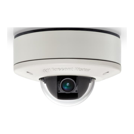
Arecont Vision MicroDome AV1455DN-S Installation Manual
Arecont vision
Hide thumbs
Also See for MicroDome AV1455DN-S:
- Installation manual (18 pages) ,
- Installation manual (18 pages)

Related Manuals for Arecont Vision MicroDome AV1455DN-S


Summary of Contents for Arecont Vision MicroDome AV1455DN-S
- Page 1 INST TALL LATIO O N MA A NUAL L AV1455 DN-S AV2455 DN-S AV2456 DN-S AV3455 DN-S AV3456 DN-S AV5455 DN-S ...
-
Page 2: Table Of Contents
MicroDome™ Surface Mount Installation Contents Package Contents ............................... 3 Warranty Information .............................. 3 Installation Overview .............................. 4 Installation ................................. 5 Focusing the Camera .............................. 7 Changing the Lens .............................. 8 Focusing Alternate Lenses ............................ 8 Digital Input and Output ............................ 9 LED Indicators ................................ 10 Support .................................. 11 Camera Discovery, Setup, and Configuration ...................... 12 Wall Mount Accessory ............................. 13 Pendant Mount Accessory ............................ 14 Mount Template: MicroDome Camera ........................ 15 Mount Template: MicroDome Wall Mount ...................... 16 Mount Template: MicroDome Pendant Mount ....................... 17 Page | 2 support@arecontvision.com... -
Page 3: Package Contents
Arecont Vision MicroDome™ Installation Manual Package Contents Item Description MegaPixel Camera MicroDome™ Mounting Kit Ceiling template 6x Mounting Screws 3/8” NPT Male to 1/2” NPT Female Adapter Network Patch Cable 3x Security Torx Dome Cover Fasteners Arecont Vision CD Manual, Warranty, Installation Software Warranty Information 3 Year Limited Warranty ARECONT VISION warrants to Purchaser (and only Purchaser) (the “Limited Warranty”), that: (a) each Product shall be free from material defects in material and workmanship for a period of thirty-six (36) months from the date of shipment (the “Warranty Period”);... -
Page 4: Installation Overview
Arecont Vision MicroDome™ Installation Manual Installation Overview Ceiling Gasket NPT Port Camera Housing Mounting Screws Gasket Captive Fasteners Dome Cover (Hand Tighten Only) Page | 4 support@arecontvision.com... -
Page 5: Installation
Arecont t Vision Mi croDome™ ™ Installati on Manua l Instal lation 1. V isit http://ww ww.arecontvi sion.com/ an d check to en nsure your ca amera has the e most curren nt firmware. 2. Fo or installation ns in harsh en nvironments i it is recomme ended to use all six mount ting screws su upplied with our camera to o create the b best seal poss sible between n your camer ra and the mo ounting surfac ce using the upplied gaske et. ... - Page 6 Arecont Vision MicroDome™ Installation Manual Page | 6 support@arecontvision.com...
-
Page 7: Focusing The Camera
Arecont t Vision Mi croDome™ ™ Installati on Manua l Focus ing the C Camera 1. O Open a live vie ew of the cam mera from you ur web brows ser or the AV Software pro ovided (AV100 0 or AV200). 2. Lo oosen the len ns lock screw using a phillip ps head screw wdriver (if ne cessary). On ly do so if len ns seems very y Tech ght when tur rning. Lock sc crew should e tightened e enough to pro ovide some riction against t the lens to a avoid ... - Page 8 Arecont t Vision Mi croDome™ ™ Installati on Manua l Chang ging the Lens 1. R emove the D ome Cover by y loosening th he captive fas steners. 2. Lo oosen the len ns lock screw using a phillip ps head screw wdriver (if ne cessary). On ly do so if len ns seems very y ght when tur rning. 3. M Manually unsc crew the lens, , this may tak ke everal second ds. 4. R eplace lens. ...
-
Page 9: Digital Input And Output
Arecont Vision MicroDome™ Installation Manual Digital Input and Output Use 4 position connector inside camera housing to interface with Digital I/O. DIGITAL I/O BLACK IN ‐ WHITE IN + YELLOW OUT ‐ ORANGE OUT + Electrical Characteristics MIN MAX ON 2.9 6.3 Input Voltage (V) (Measured between + OFF 0 1.3 and – terminals) Output Current (mA) ON ‐ 50 (Measured between + and – terminals) OFF ‐ 0.1 ... -
Page 10: Led Indicators
Arecont Vision MicroDome™ Installation Manual LED Indicators LED Status Description Yellow Flashing Link has been established. Solid Normal Operation. None No connection. Green Flashing Camera has been accessed. Normal operation. Solid None No Connection. Page | 10 support@arecontvision.com... -
Page 11: Support
Arecont Vision MicroDome™ Installation Manual Support 1. Arecont Vision FAQ Page Located at ArecontVision.com 2. Check the following before you call: Restore camera to factory default with AV100, AV200 or the camera webpage. Upgrade to the latest firmware by visiting ArecontVision.com. Isolate the camera on a dedicated network and test with AV100 or AV200. Swap the “troubled” camera with a known good camera to see if the problem follows the camera or stays at the location. 3. Contact Arecont Vision Technical Support one of three ways: 1. Online Portal : Support.ArecontVision.com 2. Phone : 1.818.937.0700 (option #1) 3. Email : support@arecontvision.com Page | 11 support@arecontvision.com... -
Page 12: Camera Discovery, Setup, And Configuration
Arecont Vision MicroDome™ Installation Manual Camera Discovery, Setup, and Configuration For camera discovery and setup please use Arecont Vision software AV200 which you can find on the CD included with your camera or at: http://www.arecontvision.com/softwares.php The user manual for the AV200 software is included on the CD and is also located on our website. To configure the camera use either the AV200 software or the web interface utility. The web interface can be accessed by typing the camera IP address into your web browser or by clicking on the web interface button in AV200. The user manual for our web interface is included on the CD and is also located on our website. Page | 12 support@arecontvision.com... -
Page 13: Wall Mount Accessory
Arecont t Vision Mi croDome™ ™ Installati on Manua l Wall M Mount A Accessor ry (MCD‐ ‐WMT) Gaske et lignment f eatures m ust be alig gned for pr roper insta allation. Installa ation Not tes: 1. A Always en nsure gask kets are p... -
Page 14: Pendant Mount Accessory
Arecont t Vision Mi croDome™ ™ Installati on Manua l Penda ant Mou unt Acce ssory (M MCD‐CM MT) Insta llation No otes: Always e ensure ga askets are e properly y seated. Use Tefl on tape o on thread ded interface es. 3/8” ma ale to 1/2” ” female NPT adapter ... -
Page 15: Mount Template: Microdome Camera
Arecont Vision MicroDome™ Installation Manual Mount Template: MicroDome Camera Page | 15 support@arecontvision.com... -
Page 16: Mount Template: Microdome Wall Mount
Arecont Vision MicroDome™ Installation Manual Mount Template: MicroDome Wall Mount Page | 16 support@arecontvision.com... -
Page 17: Mount Template: Microdome Pendant Mount
Arecont Vision MicroDome™ Installation Manual Mount Template: MicroDome Pendant Mount Page | 17 support@arecontvision.com... - Page 18 Arecont Vision MicroDome™ Installation Manual Contact Arecont Vision Technical Support one of three ways: Online Portal : Support.ArecontVision.com Phone : 1.818.937.0700 (option #1) Email : support@arecontvision.com Page | 18 support@arecontvision.com...
Need help?
Do you have a question about the MicroDome AV1455DN-S and is the answer not in the manual?
Questions and answers