
Related Manuals for Daikin SiBE04-624_B_FTXR-E


Summary of Contents for Daikin SiBE04-624_B_FTXR-E
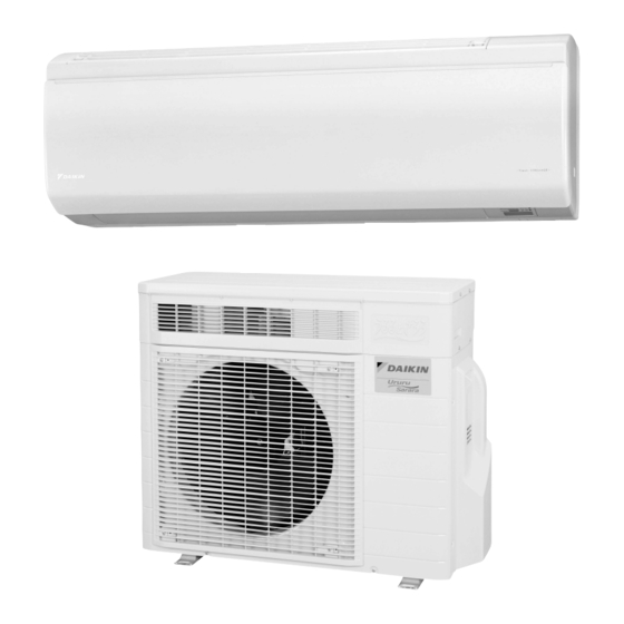
- Page 1 SiBE04-624_B Inverter Pair Wall Mounted Type E-Series [Applied Models] Inverter Pair : Heat Pump...
- Page 2 SiBE04-624_B Inverter Pair Wall Mounted Type E-Series Heat Pump Indoor Unit FTXR28EV1B9 FTXR42EV1B9 FTXR50EV1B9 Outdoor Unit RXR28EV1B9 RXR28EV1B8 RXR42EV1B9 RXR42EV1B8 RXR50EV1B9 RXR50EV1B8 The removal procedure for each model is separately bound. Refer to page 155 for the booklet number of applicable model.
-
Page 3: Table Of Contents
SiBE04-624_B 1. Introduction .....................v 1.1 Safety Cautions ..................v 1.2 Used Icons ....................ix Part 1 List of Functions ..............1 1. Functions....................2 Part 2 Specifications ..............4 1. Specifications ..................5 Part 3 Printed Circuit Board Connector Wiring Diagram ..... 9 1. - Page 4 SiBE04-624_B 2.7 Draft Prevention Control (Hot-Start Function) ........61 2.8 Dew Prevention Control .................61 2.9 Outdoor Fan Control................62 2.10 Liquid Compression Protection Function..........62 2.11 Defrost Control ..................63 2.12 Electronic Expansion Valve Control ............64 Part 5 Remote Controller ............67 1. FTXR28/42/50EV1B9................68 Part 6 Service Diagnosis.............
- Page 5 SiBE04-624_B 2.36 Radiation Fin Temperature Rise ............126 2.37 Output Overcurrent Detection ..............128 2.38 Fan Motor System Abnormality / Fan Lock ..........130 2.39 Heater Wire Abnormality ..............131 2.40 Humidifying Thermistor Abnormality / Humidifying Heater Temperature Abnormality ........132 3. Check ....................134 3.1 Thermistor Resistance Check ..............134 3.2 Fan Motor Connector Output Check ............135 3.3 Humidity Sensor Check................135 3.4 Power Supply Waveforms Check............135...
-
Page 6: Introduction
Introduction SiBE04-624_B 1. Introduction Safety Cautions Cautions and Be sure to read the following safety cautions before conducting repair work. The caution items are classified into “ Warning” and “ Caution”. The “ Warning” Warnings items are especially important since they can lead to death or serious injury if they are not followed closely. - Page 7 SiBE04-624_B Introduction Warning Be sure to wear a safety helmet, gloves, and a safety belt when working at a high place (more than 2 m). Insufficient safety measures may cause a fall accident. In case of R-410A refrigerant models, be sure to use pipes, flare nuts and tools for the exclusive use of the R-410A refrigerant.
- Page 8 Introduction SiBE04-624_B 1.1.2 Cautions Regarding Safety of Users Warning Be sure to use parts listed in the service parts list of the applicable model and appropriate tools to conduct repair work. Never attempt to modify the equipment. The use of inappropriate parts or tools may cause an electrical shock, excessive heat generation or fire.
- Page 9 SiBE04-624_B Introduction Warning Check to make sure that the power cable plug is not dirty or loose, then insert the plug into a power outlet securely. If the plug has dust or loose connection, it may cause an electrical shock or fire. Be sure to install the product correctly by using the provided standard For unitary type installation frame.
-
Page 10: Used Icons
Introduction SiBE04-624_B Caution Be sure to measure the insulation resistance after the repair, and make sure that the resistance is 1 MΩ or higher. Faulty insulation may cause an electrical shock. Be sure to check the drainage of the indoor unit after the repair. Faulty drainage may cause the water to enter the room and wet the furniture and floor. -
Page 11: Part 1 List Of Functions
SiBE04-624_B Part 1 List of Functions 1. Functions....................2 List of Functions... -
Page 12: Functions
Functions SiBE04-624_B 1. Functions Category Functions Category Functions Basic Inverter (with inverter power control) Health & Air purifying filter — Function Clean –10 Photocatalytic deodorizing filter — Operation limit for cooling (°CDB) Air purifying filter with photocatalytic — –20 deodorizing function Operation limit for heating (°CWB) Titanium apatite photocatalytic PAM control... - Page 13 SiBE04-624_B Functions Category Functions Category Functions Basic Inverter (with inverter power control) Health & Air purifying filter — Function Clean –10 Photocatalytic deodorizing filter — Operation limit for cooling (°CDB) Air purifying filter with photocatalytic — –20 deodorizing function Operation limit for heating (°CWB) Titanium apatite photocatalytic PAM control air purifying filter...
-
Page 14: Part 2 Specifications
SiBE04-624_B Part 2 Specifications 1. Specifications ..................5 Specifications... -
Page 15: Specifications
SiBE04-624_B Specifications 1. Specifications 50 Hz, 220 - 230 - 240 V Indoor Unit FTXR28EV1B9 FTXR42EV1B9 Model RXR28EV1B9 RXR42EV1B9 Outdoor Unit Cooling Heating Cooling Heating 2.8 (1.55 ~ 3.60) 3.6 (1.30 ~ 5.00) 4.2 (1.55 ~ 4.60) 5.1 (1.30 ~ 5.60) Capacity Btu/h 9,600 (5,300 ~ 12,300) - Page 16 Specifications SiBE04-624_B 50 Hz, 220 - 230 - 240 V Indoor Unit FTXR50EV1B9 Model RXR50EV1B9 Outdoor Unit Cooling Heating 5.0 (1.55 ~ 5.50) 6.0 (1.30 ~ 6.20) Capacity Btu/h 17,100 (5,300 ~ 18,800) 20,500 (4,400 ~ 21,200) Rated (Min. ~ Max.) kcal/h 4,300 (1,330 ~ 4,730) 5,160 (1,120 ~ 5,330)
- Page 17 SiBE04-624_B Specifications 50 Hz, 220 - 230 - 240 V Indoor Unit FTXR28EV1B9 FTXR42EV1B9 Model RXR28EV1B8 RXR42EV1B8 Outdoor Unit Cooling Heating Cooling Heating 2.8 (1.55 ~ 3.60) 3.6 (1.30 ~ 5.00) 4.2 (1.55 ~ 4.60) 5.1 (1.30 ~ 5.60) Capacity Btu/h 9,600 (5,300 ~ 12,300) 12,300 (4,400 ~ 17,100)
- Page 18 Specifications SiBE04-624_B 50 Hz, 220 - 230 - 240 V Indoor Unit FTXR50EV1B9 Model RXR50EV1B8 Outdoor Unit Cooling Heating 5.0 (1.55 ~ 5.50) 6.0 (1.30 ~ 6.20) Capacity Btu/h 17,100 (5,300 ~ 18,800) 20,500 (4,400 ~ 21,200) Rated (Min. ~ Max.) kcal/h 4,300 (1,330 ~ 4,730) 5,160 (1,120 ~ 5,330)
-
Page 19: Part 3 Printed Circuit Board Connector Wiring Diagram
SiBE04-624_B Part 3 Printed Circuit Board Connector Wiring Diagram 1. Indoor Unit.....................10 2. Outdoor Unit..................13 Printed Circuit Board Connector Wiring Diagram... -
Page 20: Indoor Unit
Indoor Unit SiBE04-624_B 1. Indoor Unit A1P: Control PCB 1) S1 Connector for fan motor 2) S21 Connector for centralized control (HA) 3) S32 Indoor heat exchanger thermistor (R1T) 4) S41 Connector for swing motors (horizontal, vertical) 5) S43 Connector for dehumidifying solenoid valve coils 6) S46 Connector for display PCB 7) S48... - Page 21 SiBE04-624_B Indoor Unit A2P: Display PCB 1) S56 Connector for control PCB 2) S57 Connector for signal receiver / transmitter PCB 3) S63 (H1P) Connector for LED PCB (multi monitor) 4) JA Address setting jumper *Refer to page 150 for detail. 5) SW1 (S1W) Forced cooling operation [ON/OFF] button *Refer to page 147 for detail.
- Page 22 Indoor Unit SiBE04-624_B A4P: Humidity Sensor PCB 1) CN1 Connector for control PCB 2) R2T Room temperature thermistor Humidity sensor 3P163282-1 A5P: Streamer Unit PCB 1) S401 Connector for control PCB 2) S402 Connector for limit switch for streamer 3) S403 Connector for streamer S402 S401...
-
Page 23: Outdoor Unit
SiBE04-624_B Outdoor Unit 2. Outdoor Unit PCB Detail 1) S20 Connector for electronic expansion valve coil 2) S21 Connector for humidifying rotor motor 3) S22 Connector for damper motor 4) S45 Connector for thermal fuse (102°C) 5) S70 Connector for fan motor 6) S72 Connector for humidifier fan motor 7) S80... -
Page 24: Part 4 Function And Control
SiBE04-624_B Part 4 Function and Control 1. Main Functions..................15 1.1 Temperature Control ................15 1.2 Frequency Principle................15 1.3 Airflow Direction Control.................17 1.4 Fan Speed Control for Indoor Unit ............20 1.5 Thermostat Control.................21 1.6 “URURU” HUMIDIFYING / HUMID HEATING Operation.......22 1.7 “SARARA” DRYING / DRY COOLING Operation ........30 1.8 AUTO Operation..................32 1.9 MOISTURIZING Operation ..............33 1.10 FLASH STREAMER AIR PURIFYING Operation ........34... -
Page 25: Main Functions
SiBE04-624_B Main Functions 1. Main Functions Temperature Control Definitions of The definitions of temperatures are classified as following. Temperatures Room temperature: temperature of lower part of the room Set temperature: temperature set by remote controller Room thermistor temperature: temperature detected by room temperature thermistor Target temperature: temperature determined by microcomputer Target temperature Room thermistor temperature... - Page 26 Main Functions SiBE04-624_B Drawing of The following drawing shows a schematic view of the inverter principle: Inverter Refrigerant circulation rate (high) high speed Amount of heat Amount of heat exchanged air (large) exchanged air (large) high f low f Amount of heat Amount of heat exchanged air (small) exchanged air (small)
-
Page 27: Airflow Direction Control
SiBE04-624_B Main Functions Airflow Direction Control 1.3.1 Power-Airflow Dual Flaps The large flaps send a large volume of air downward to the floor and provide an optimum control in cooling, dry, and heating operation. <Cooling / Dry> During cooling or dry operation, the flap retracts into the indoor unit. Then, cool air can be blown far and pervaded all over the room. - Page 28 Main Functions SiBE04-624_B 1.3.5 COMFORT AIRFLOW Operation The indication changes every time “ ” is pressed. Displays COMFORT Displays COOLING Indication disappears AIRFLOW operation BREEZE operation COMFORT AIRFLOW Operation (R13852) Effective mode for COMFORT AIRFLOW operation AUTO HEATING HUMID HEATING COOLING “SARARA”...
- Page 29 SiBE04-624_B Main Functions 1.3.6 COOLING BREEZE Operation Operation The indication changes every time “ ” is pressed. Displays COMFORT Displays COOLING Indication disappears AIRFLOW operation BREEZE operation COOLING BREEZE Operation (R13855) Effective mode for COOLING BREEZE operation • COOLING • “SARARA” DRYING •...
-
Page 30: Fan Speed Control For Indoor Unit
Main Functions SiBE04-624_B Fan Speed Control for Indoor Unit Outline Phase control and fan speed control contains 9 steps: LLL, LL, SL, L, ML, M, MH, H, and HH. The airflow rate can be automatically controlled depending on the difference between the room thermistor temperature and the target temperature. -
Page 31: Thermostat Control
SiBE04-624_B Main Functions Thermostat Control Outline Thermostat control is based on the difference between the room thermistor temperature and the target temperature. Detail Thermostat OFF Condition The temperature difference is in the zone A. Thermostat ON Condition The temperature difference returns to the zone C after being in the zone A. The system resumes from defrost control in any zones except A. -
Page 32: Ururu" Humidifying / Humid Heating Operation
Main Functions SiBE04-624_B “URURU” HUMIDIFYING / HUMID HEATING Operation Operation "URURU" HUMIDIFYING operation HUMID HEATING operation (R13858) Features Humidifying method This method intakes moisture from the outdoor air using the hygroscopic element mounted in the outdoor unit, and sends it indoor. This enables powerful and speedy humidification. taking in outdoor moisture fully humidifying the room (R18141) - Page 33 SiBE04-624_B Main Functions Powerful humidifying ability The humidifying capacity is 450 ml/h (50 class) and equivalent to that of a normal humidifier. Model 28 class 42 class 50 class Humidifying Capacity 400 ml/h 425 ml/h 450 ml/h The values above are measured at 7°CDB / 6°CWB of outdoor air temperature and 7.5 m humidifying hose length.
- Page 34 Main Functions SiBE04-624_B Humidity During HUMID HEATING operation, as room temperature rises, relative humidity is temporarily lowered. This is because as room temperature rises, relative humidity is lowered even if the Fluctuation by moisture content is the same. Temperature Settings EX: The rise in the room temperature from 15°C to 25°C results in the fall in humidity from 40%RH to about 22%RH.
- Page 35 SiBE04-624_B Main Functions Time chart for Approximately 1 minute after heating operation starts, humidifying operation and drying operation repeats alternately to prevent condensation inside the hose. humidifying operation control Heating Approx. 1 min. operation Approx. 3 min. Humidifying fan damper (b') (b') Hygroscopic...
- Page 36 Main Functions SiBE04-624_B Humidification The humidifying of this system is different from that of a normal humidifier. The humidifying performance varies depending on the outdoor temperature or installation condition. performance by Sufficient humidifying capacity may not be attained depending on the weather condition. outdoor When the outdoor temperature drops by 5°C, the humidifying capacity decreases by about temperature...
- Page 37 SiBE04-624_B Main Functions Reachable Humidifying capacity drops when the outdoor temperature and the outdoor humidity are low. humidity by 28 class outdoor condition Condition; Set temperature: 20°C Airflow rate: H tap Room volume: 70 m Ventilation rate: 0.5 times/hour Humidifying hose length: 7.5 m –10 Outdoor temperature (°C) (R13866)
- Page 38 Main Functions SiBE04-624_B Performance The maximum piping length is set to 10 m, but the humidifying capacity varies depending on the length of the humidifying hose. correction by When the hose length increases by 2 m, the humidifying capacity decreases by about 10%. hose length Outdoor temp.
- Page 39 SiBE04-624_B Main Functions Room humidity (humidity of the discharged air) by outdoor temperature (16 m , hose length: 4 m, ventilation rate: 0.75 times/hour, 28 class) 1. Room temp. 17°CDB 100% Outdoor relative humidity 80%RH 60%RH 40%RH –10 –5 Outdoor temperature (˚C) (R13872) 2.
-
Page 40: Sarara" Drying / Dry Cooling Operation
Main Functions SiBE04-624_B “SARARA” DRYING / DRY COOLING Operation Operation DRY COOLING "SARARA" DRYING operation operation (R13875) Features of Reheating dehumidifying method A powerful evaporator eliminates the humidity in the room exclusively. Dry, cool air is mixed “SARARA” with warm air from the reheater, thereby blowing in optimal and comfortable dry air. DRYING Indoor heat exchanger as condenser (warmed) - Page 41 SiBE04-624_B Main Functions Differences between “SARARA” DRYING and DRY COOLING operation “SARARA” DRYING DRY COOLING Method Pressure reducing devices (solenoid valves) are Like COOLING operation, DRY COOLING located at the center of the indoor heat exchanger. operation raises latent heat capacity with The upper side acts as a condenser to heat the air.
-
Page 42: Auto Operation
Main Functions SiBE04-624_B AUTO Operation Operation AUTO operation (R5985) Outline Automatic Cooling / Heating Function When the AUTO operation is selected with the remote controller, the microcomputer automatically determines the operation mode as cooling or heating according to the room temperature and the set temperature at start-up. -
Page 43: Moisturizing Operation
SiBE04-624_B Main Functions MOISTURIZING Operation Operation MOISTURIZING operation (R13878) Effective mode for MOISTURE COOLING operation • COOLING • DRY COOLING Effective mode for MOISTURE HEATING operation • HEATING • HUMID HEATING Features MOISTURIZING operation has following 3 features. • Relatively high humidity setting •... -
Page 44: Flash Streamer Air Purifying Operation
Features The same technology as for real air purifiers is adopted. The original technology FLASH STREAMER system used for Daikin’s air purifiers is incorporated. This technology realizes air purifying exceeding the performance of a normal air conditioner and powerfully decomposes diesel dust, NO , mold, viruses, etc. - Page 45 The formaldehyde concentration in the laboratory (10 m ) at 0.5-time natural ventilation and the initial concentration setting of 0.3 ppm (Observed by Daikin using 28 class model) (Nozaki laboratory, Graduate Course of Health and Society System, Tohoku Bunka Gakuen University)
-
Page 46: Fresh Air Supply Ventilation Operation
Main Functions SiBE04-624_B 1.11 FRESH AIR SUPPLY VENTILATION Operation Operation The indication changes every time “ ” is pressed. FLASH STREAMER AIR PURIFYING FLASH STREAMER AIR PURIFYING FLASH STREAMER AIR PURIFYING FRESH AIR SUPPLY VENTILATION Strong FRESH AIR SUPPLY VENTILATION FRESH AIR SUPPLY VENTILATION operation (R5977) <Note>... -
Page 47: Home Leave Ventilation
SiBE04-624_B Main Functions Ventilation System Ventilation is mainly divided into two types. The convenient system is supply ventilation. Supply Ventilation Exhaust Ventilation Fresh Air Supply Draft (R5979) - Quiet because the ventilation fan is located in - Operation noise is heard because the ventilation the outdoor unit fan is located in the room. -
Page 48: Timer Operation
Main Functions SiBE04-624_B 1.13 TIMER Operation 1.13.1 24-hour ON/OFF TIMER Operation Set the time ON/OFF TIMER Cancel (R13885) Features Time can be set in the unit of 10 minutes. When the 24-hour ON/OFF TIMER is set, the indication of present time disappears. Time is kept in memory in the next operation unless it is canceled. -
Page 49: Night Set Mode
SiBE04-624_B Main Functions 1.14 NIGHT SET Mode Outline When the OFF timer is set, the NIGHT SET Mode is automatically activated. The NIGHT SET Mode keeps the airflow rate setting. Detail The NIGHT SET Mode continues operation at the target temperature for the first one hour, then automatically raises the target temperature slightly in the case of cooling, or lowers it slightly in the case of heating. -
Page 50: Comfort Sleep Operation
Main Functions SiBE04-624_B 1.15 COMFORT SLEEP Operation Operation Set the time to wake up. COMFORT SLEEP operation (R13887) Effective mode for COMFORT SLEEP operation • COOLING • DRY COOLING • MOISTURE COOLING • HEATING • HUMID HEATING • MOISTURE HEATING Features Outline of function The temperature is controlled in unique V-shape pattern within the range of about 2°C upper... - Page 51 SiBE04-624_B Main Functions Human sleep Sleep cycle and change in body temperature → Time (˚C) Sharp lowering of Maximum difference body temperature Rising of body of change in body Sleep cycle after falling asleep temperature before temperature wake-up Awakening REM sleep Smooth shift to awakening Deep sleep...
-
Page 52: Powerful Operation
Main Functions SiBE04-624_B 1.16 POWERFUL Operation Operation POWERFUL operation (Cannot be used while the unit is not running.) (R5971) Effective mode for POWERFUL COOLING operation • COOLING • DRY COOLING • MOISTURE COOLING Effective mode for POWERFUL HEATING operation • HEATING •... -
Page 53: Mold Proof Operation
SiBE04-624_B Main Functions 1.17 MOLD PROOF Operation This is an integrated naming of functions of inside drying and moisture exhaustion. Drying inside the air conditioner prevents mold and odors from growing. Operation Operation can be selected from automatic and manual. Automatic operation If MOLD PROOF operation is set ON, the MOLD PROOF operation starts automatically after “SARARA”... - Page 54 Main Functions SiBE04-624_B 1. Drained water discharge 2. Inside drying operation Drained water in the drain pan is discharged. After the drained water discharged, the moisture which are left on the drain pan or the indoor heat exchanger are dried by evaporation. 3.
-
Page 55: Mold Shock Out Operation
With MOLD SHOCK OUT operation operation operation Fewer molds grow as compared with the case The test was conducted at DAIKIN’s laboratory with use of the of without MOLD SHOCK OUT Operation. mold sensor of Environmental Biological Research Institute. (R13897) Time chart •... - Page 56 Main Functions SiBE04-624_B Comparison of COOLING operation and MOLD SHOCK OUT operation Normal COOLING operation The humidity in the room returns to original level when COOLING operation stops. Humidity COOLING start COOLING stop Time Growth of mold Mold grows according to the humidity.
- Page 57 SiBE04-624_B Main Functions Reference Effect MOLD SHOCK OUT operation. <27˚C, 75 - 85 %, reheating dehumidifying (–3˚C)> Humidity % Without MOLD SHOCK OUT operation Before MOLD SHOCK OUT operation Humidity (indoor) Humidity without MOLD SHOCK OUT operation With MOLD SHOCK OUT operation Outdoor temperature Room temperature...
-
Page 58: Information Display
Main Functions SiBE04-624_B 1.19 INFORMATION DISPLAY Operation INFORMATION Return to normal display Set temperature Room temperature Outdoor Indoor humidity temperature (R13901) Features After pressing the [INFO] button, point the remote controller at the indoor unit for 2 seconds. Every time you press the [INFO] button, room temperature, indoor humidity, and outdoor temperature are displayed. -
Page 59: Multi-Colored Indicator Lamp
SiBE04-624_B Main Functions 1.20 Multi-colored Indicator Lamp Features The current operation mode is displayed in color of the lamp of the indoor unit which changes in 8 colors. Operating status can be monitored even in AUTO operation in accordance with the actual operation. -
Page 60: Clock Setting
Main Functions SiBE04-624_B 1.23 Clock Setting ARC447 Series The clock can be set by taking the following steps: 1. Press the [CLOCK] button. → is displayed and blinks. 2. Press the [SELECT] button to set the clock to the present time. Holding down the [SELECT] button increases or decreases the time display rapidly. -
Page 61: Other Functions
SiBE04-624_B Main Functions 1.25 Other Functions 1.25.1 Hot-Start Function In order to prevent the cold air blast that normally comes when heating operation is started, the temperature of the indoor heat exchanger is detected, and the airflow is either stopped or made very weak thereby carrying out comfortable heating of the room. -
Page 62: Table For Special Modes
Main Functions SiBE04-624_B 1.26 Table for Special Modes Indoor [ON/OFF] 5~9 sec. • Operation OFF Forced cooling operation mode • Left for 15 min. [CANCEL] 5 sec. • [CANCEL] 5 sec. Diagnosis mode • Left for 60 sec. Mode selection view: Select with [SELECT] button. - Page 63 SiBE04-624_B Main Functions 1. Trial operation mode: You can select a mode for trial operation with the remote controller. The operation continues for approx. 30 minutes. Refer to the installation manual. 2. Hose length setting mode: You can set the humidifying hose length or check the preset value. Refer to the installation manual.
-
Page 64: Control Specification
Control Specification SiBE04-624_B 2. Control Specification Frequency Control Outline Frequency is determined according to the difference between the room thermistor temperature and the target temperature. The function is explained as follows. 1. How to determine frequency 2. Frequency command from the indoor unit (Difference between the room thermistor temperature and the target temperature) 3. - Page 65 SiBE04-624_B Control Specification Indoor Frequency Command (∆D signal) The difference between the room thermistor temperature and the target temperature is taken as the “∆D signal” and is used for frequency command. ∆D ∆D ∆D ∆D Temperature Temperature Temperature Temperature difference signal difference signal...
-
Page 66: Controls At Mode Changing / Start-Up
Control Specification SiBE04-624_B Controls at Mode Changing / Start-up 2.2.1 Preheating Operation Outline The inverter operation in open phase starts with the conditions of the preheating command from the indoor unit, the outdoor temperature, and the discharge pipe temperature. Outdoor temperature ≥ 7°C Detail Preheating OFF 12˚C... - Page 67 SiBE04-624_B Control Specification 2.2.4 3-minute Standby Turning on the compressor is prohibited for 3 minutes after turning it off. (Except when defrosting.) 2.2.5 Compressor Protection Function When turning the compressor from OFF to ON, the upper limit of frequency is set as follows. (The function is not activated when defrosting.) (Hz) Frequency...
-
Page 68: Discharge Pipe Temperature Control
Control Specification SiBE04-624_B Discharge Pipe Temperature Control Outline The discharge pipe temperature is used as the internal temperature of the compressor. If the discharge pipe temperature rises above a certain level, the upper limit of frequency is set to keep the discharge pipe temperature from rising further. Detail Stop zone 118 –... -
Page 69: Input Current Control
SiBE04-624_B Control Specification Input Current Control Outline The microcomputer calculates the input current while the compressor is running, and sets the frequency upper limit from the input current. In case of heat pump model, this control which is the upper limit control of the frequency takes priority to the lower limit of control of four way valve operation compensation. -
Page 70: Freeze-Up Protection Control
Control Specification SiBE04-624_B Freeze-up Protection Control Outline During cooling operation, the signal sent from the indoor unit controls the operating frequency limitation and prevents freezing of the indoor heat exchanger. (The signal from the indoor unit is divided into zones.) Detail The operating frequency limitation is judged with the indoor heat exchanger temperature. -
Page 71: Draft Prevention Control (Hot-Start Function)
SiBE04-624_B Control Specification Draft Prevention Control (Hot-Start Function) Outline Draft prevention control prevents cold draft when the unit is started up in heating operation. This function is activated when the indoor heat exchanger temperature drops. Detail Draft prevention control is conducted by monitoring indoor heat exchanger temperature. When the indoor heat exchanger temperature drops below 33°C, the minimum frequency of the compressor increases. -
Page 72: Outdoor Fan Control
Control Specification SiBE04-624_B Outdoor Fan Control 1. Fan ON control to cool down the electrical box The outdoor fan is turned ON when the electrical box temperature is high while the compressor is OFF. 2. Fan OFF control while defrosting The outdoor fan is turned OFF while defrosting. -
Page 73: Defrost Control
SiBE04-624_B Control Specification 2.11 Defrost Control Outline Defrosting is carried out by the cooling cycle (reverse cycle). The defrosting time or outdoor heat exchanger temperature must be more than a certain value to finish. Detail Conditions for Starting Defrost The starting conditions is determined with the outdoor temperature and the outdoor heat exchanger temperature. -
Page 74: Electronic Expansion Valve Control
Control Specification SiBE04-624_B 2.12 Electronic Expansion Valve Control Outline The following items are included in the electronic expansion valve control. Electronic expansion valve is fully closed 1. Electronic expansion valve is fully closed when turning on the power. 2. Pressure equalizing control Open Control 1. - Page 75 SiBE04-624_B Control Specification 2.12.1 Fully Closing with Power ON The electronic expansion valve is initialized when turning on the power. The opening position is set and the pressure equalization is developed. 2.12.2 Pressure Equalizing Control When the compressor is stopped, the pressure equalizing control is activated. The electronic expansion valve opens, and develops the pressure equalization.
- Page 76 Control Specification SiBE04-624_B 2.12.7 Control for Disconnection of the Discharge Pipe Thermistor Outline The disconnection of the discharge pipe thermistor is detected by comparing the discharge pipe temperature with the condensation temperature. If the discharge pipe thermistor is disconnected, the electronic expansion valve opens according to the outdoor temperature and the operation frequency, and operates for a specified time, and then stops.
-
Page 77: Part 5 Remote Controller
SiBE04-624_B Part 5 Remote Controller 1. FTXR28/42/50EV1B9................68 Remote Controller... -
Page 78: Ftxr28/42/50Ev1B9
VENTILATION Operation 5 “URURU” HUMIDIFYING / HUMID HEATING Operation Note: Refer to the operation manual of applicable model for detail. You can download operation manual from ‘DISTRIBUTOR’S PAGE’: DISTRIBUTOR’S PAGE → Product Information → Operation/Installation Manual (URL: http://global.daikin.com/Daikin/global/Distributors_admin/user_mng/login.php) Remote Controller... - Page 79 21 COMFORT SLEEP Operation 15 Clock Setting 22 RESET Note: Refer to the operation manual of applicable model for detail. You can download operation manual from ‘DISTRIBUTOR’S PAGE’: DISTRIBUTOR’S PAGE → Product Information → Operation/Installation Manual (URL: http://global.daikin.com/Daikin/global/Distributors_admin/user_mng/login.php) Remote Controller...
- Page 80 FTXR28/42/50EV1B9 SiBE04-624_B Temperature and Heating “URURU” HUMIDIFYING Operation Humidity Settings HEATING HUMID HEATING “URURU” HUMIDIFYING 10˚C – 30˚C –––––– HIGH CONT HIGH CONT Cooling “SARARA” DRYING Operation COOLING DRY COOLING “SARARA” DRYING 18˚C – 32˚C –3˚C – STD HIGH CONT HIGH CONT AUTO Operation...
-
Page 81: Part 6 Service Diagnosis
SiBE04-624_B Part 6 Service Diagnosis 1. Convenient Service Check Function .............73 1.1 Indoor Unit....................73 1.2 Outdoor Unit ...................73 2. Troubleshooting ..................74 2.1 Error Codes and Description ..............74 2.2 Air conditioner does not run..............75 2.3 Air conditioner runs but does not cool (heat) the room......78 2.4 When operation starts, safety breaker works. - Page 82 SiBE04-624_B 2.40 Humidifying Thermistor Abnormality / Humidifying Heater Temperature Abnormality ........132 3. Check ....................134 3.1 Thermistor Resistance Check ..............134 3.2 Fan Motor Connector Output Check ............135 3.3 Humidity Sensor Check................135 3.4 Power Supply Waveforms Check............135 3.5 Electronic Expansion Valve Check............136 3.6 Four Way Valve Performance Check ...........137 3.7 Inverter Units Refrigerant System Check ..........138 3.8 Inverter Analyzer Check ...............138...
-
Page 83: Convenient Service Check Function
SiBE04-624_B Convenient Service Check Function 1. Convenient Service Check Function Indoor Unit Multi-colored The multi-colored indicator lamp blinks when any of the following errors is detected. 1. When a protection device of the indoor or outdoor unit is activated, or when the thermistor Indicator Lamp malfunctions. -
Page 84: Troubleshooting
Troubleshooting SiBE04-624_B 2. Troubleshooting Error Codes and Description Code Unit Description Reference page Air conditioner does not run. Air conditioner runs but does not cool (heat) the room. Basic Failure Diagnosis When operation starts, safety breaker works. Air conditioner makes big noise and vibration. Air is not humidified enough. -
Page 85: Air Conditioner Does Not Run
SiBE04-624_B Troubleshooting Air conditioner does not run. Error Code Error Decision Conditions Supposed Power supply is OFF. Causes Improper power supply voltage Improper connection of wire Incorrect combination of indoor unit and outdoor unit Battery shortage of remote controller Invalid address setting Protection device works (dirty air filter, refrigerant shortage, overfilling, mixed air, etc.) Transmission error between indoor unit and outdoor unit... - Page 86 Troubleshooting SiBE04-624_B Troubleshooting Be sure to turn off the power switch before connecting or disconnecting Caution connectors, or parts may be damaged. Is the power supply plug inserted into the Insert the power supply outlet or the breaker for plug into the outlet. Turn on the power supply the breaker for the power breaker ON?
- Page 87 SiBE04-624_B Troubleshooting Continued from the previous page Is there a sound Are the batteries indicating that a signal in the remote Replace the batteries. from the remote controller controller flat? is received? Does the address of the remote controller match with Match the address.
-
Page 88: Air Conditioner Runs But Does Not Cool (Heat) The Room
Troubleshooting SiBE04-624_B Air conditioner runs but does not cool (heat) the room. Error Code Error Decision Conditions Supposed Improper setting for temperature Causes Incorrect combination of indoor unit and outdoor unit Clogged air filter Insufficient power Refrigerant piping is too long Defective field piping (squeezed, etc.) Service Diagnosis... - Page 89 SiBE04-624_B Troubleshooting Troubleshooting Be sure to turn off the power switch before connecting or disconnecting Caution connectors, or parts may be damaged. Check No.01 Is the set Refer to P.134 temperature Thermostat off is activated. appropriate? Set the appropriate temperature. Is there required Provide required space.
-
Page 90: When Operation Starts, Safety Breaker Works
Troubleshooting SiBE04-624_B When operation starts, safety breaker works. Error Code Error Decision Conditions Supposed Insufficient capacity of safety breaker Causes Earth leakage breaker is too sensitive. Not exclusive circuit The supply voltage is not within rated voltage ±10%. The size of connecting wire is thin. Air is mixed. - Page 91 SiBE04-624_B Troubleshooting Troubleshooting Be sure to turn off the power switch before connecting or disconnecting Caution connectors, or parts may be damaged. Check No.20 [Power supply] Refer to P.142 Is the capacity of Replace the safety breaker safety breaker as to a specified one.
-
Page 92: Air Conditioner Makes Big Noise And Vibration
Troubleshooting SiBE04-624_B Air conditioner makes big noise and vibration. Error Code Error Decision Conditions Supposed Refrigerant piping is too short. Causes Mounting wall is too thin. Insufficient vibration prevention measures Deformation of the unit Improper quantity of refrigerant Troubleshooting Be sure to turn off the power switch before connecting or disconnecting Caution connectors, or parts may be damaged. -
Page 93: Air Is Not Humidified Enough
SiBE04-624_B Troubleshooting Air is not humidified enough. Error Code Error Decision Conditions Supposed Hose length is not set. Causes Improper setting for hose length Air is short-circuited at outdoor unit. Clogged air supply filter Insufficient heat insulation of duct Indoor ventilation is made too often. Ceiling is very high. - Page 94 Repair breakage or remove blockage on humidification blockage. hose? Is the humidification Use the proper hose hose proper? specified by DAIKIN. Does the outdoor unit suck the Improve so as not to get exhausted air again by short-circuit. short-circuit? YES (screens, consecutives room ) Is the room ventilated Explain to the user.
-
Page 95: Lights-Out Of Microcomputer Status Lamp
SiBE04-624_B Troubleshooting Lights-out of Microcomputer Status Lamp Error Code No display Method of Error When a microcomputer fault is detected, LED A or LED 5 turns off. Detection Error Decision Conditions Supposed Outdoor unit PCB is not power supplied Power supply failure due to noise Causes Troubleshooting Be sure to turn off the power switch before connecting or disconnecting... -
Page 96: Indoor Unit Pcb Abnormality
Troubleshooting SiBE04-624_B Indoor Unit PCB Abnormality Error Code Method of Error The system checks if the circuit works properly within the microcomputer of the indoor unit. Detection Error Decision The system cannot set the internal settings. Conditions Supposed Wrong models interconnected Defective indoor unit PCB Causes Disconnection of connector... -
Page 97: Freeze-Up Protection Control Or Heating Peak-Cut Control
SiBE04-624_B Troubleshooting Freeze-up Protection Control or Heating Peak-cut Control Error Code Method of Error Freeze-up protection control During cooling operation, the freeze-up protection control (operation halt) is activated Detection according to the temperature detected by the indoor heat exchanger thermistor. Heating peak-cut control During heating operation, the temperature detected by the indoor heat exchanger thermistor is used for the heating peak-cut control (operation halt, outdoor fan stop, etc.) - Page 98 Troubleshooting SiBE04-624_B Troubleshooting Be sure to turn off the power switch before connecting or disconnecting Caution connectors, or parts may be damaged. Check No.01 Check the air passage. Refer to P.134 Is there any short circuit? Provide sufficient air passage. Check the air filter.
-
Page 99: Fan Motor (Dc Motor) Or Related Abnormality
SiBE04-624_B Troubleshooting 2.10 Fan Motor (DC Motor) or Related Abnormality Error Code Method of Error The rotation speed detected by the Hall IC during fan motor operation is used to determine Detection abnormal fan motor operation. Error Decision The detected rotation speed does not reach the demanded rotation speed of the target tap, and is less than 50% of the maximum fan motor rotation speed. - Page 100 Troubleshooting SiBE04-624_B Troubleshooting Be sure to turn off the power switch before connecting or disconnecting Caution connectors, or parts may be damaged. Check No.02 Turn off the power supply Refer to P.135 and rotate the fan by hand. Does the fan Replace the indoor rotate smoothly? fan motor.
-
Page 101: Streamer Unit Abnormality
SiBE04-624_B Troubleshooting 2.11 Streamer Unit Abnormality Error Code Method of Error Detection Error Decision If the error repeats in air purifying operation, the system is shut down. Reset condition: Continuous run for about 2 minutes without any other error Conditions Supposed Short circuit caused by dust or drip of water on the electrode unit of the streamer unit Scratch or crack in the harness for the streamer unit... - Page 102 Troubleshooting SiBE04-624_B Troubleshooting Be sure to turn off the power switch before connecting or disconnecting Caution connectors, or parts may be damaged. Dust or drip of water is Clean the streamer unit. on the streamer unit. Does the multi-colored indicator lamp blink about 1 Clean the streamer unit.
-
Page 103: Thermistor Or Related Abnormality (Indoor Unit)
SiBE04-624_B Troubleshooting 2.12 Thermistor or Related Abnormality (Indoor Unit) C4, C9 Error Code Method of Error The temperatures detected by the thermistors determine thermistor errors. Detection Error Decision The thermistor input is more than 4.96 V or less than 0.04 V during compressor operation. Conditions Supposed Disconnection of connector... -
Page 104: Front Panel Open / Close Abnormality
Troubleshooting SiBE04-624_B 2.13 Front Panel Open / Close Abnormality Error Code Method of Error Detection Error Decision If the error repeats, the system is shut down. Conditions Supposed Defective reduction motor Malfunction or deterioration of the front panel mechanism Causes Defective limit switch Troubleshooting Be sure to turn off the power switch before connecting or disconnecting... -
Page 105: Humidity Sensor Abnormality
SiBE04-624_B Troubleshooting 2.14 Humidity Sensor Abnormality Error Code Method of Error Sensor abnormality is detected by input value. Detection Error Decision The input from the humidity sensor is 4.96 V or more or 0.04 V or less. Conditions Supposed Disconnection of connector Defective indoor unit PCB (humidity sensor PCB, control PCB) Causes Defective humidity sensor... -
Page 106: Refrigerant Shortage
Troubleshooting SiBE04-624_B 2.15 Refrigerant Shortage Error Code Method of Error Refrigerant shortage detection I: Refrigerant shortage is detected by checking the input current value and the compressor Detection running frequency. If the refrigerant is short, the input current is lower than the normal value. Refrigerant shortage detection III: Refrigerant shortage is detected by checking the difference between suction and discharge temperature. - Page 107 SiBE04-624_B Troubleshooting Troubleshooting Be sure to turn off the power switch before connecting or disconnecting Caution connectors, or parts may be damaged. Check No.01 Refer to P.134 Any thermistor Replace the thermistor(s) disconnected? ∗ Discharge pipe thermistor position. ∗ Indoor or outdoor heat exchanger thermistor ∗...
-
Page 108: Low-Voltage Detection Or Over-Voltage Detection
Troubleshooting SiBE04-624_B 2.16 Low-voltage Detection or Over-voltage Detection Error Code Method of Error Low-voltage detection: An abnormal voltage drop is detected by the DC voltage detection circuit. Detection Over-voltage detection: An abnormal voltage rise is detected by the over-voltage detection circuit. Error Decision Low-voltage detection: The voltage detected by the DC voltage detection circuit is below 150 V. - Page 109 SiBE04-624_B Troubleshooting Troubleshooting Be sure to turn off the power switch before connecting or disconnecting Caution connectors, or parts may be damaged. Check the supply voltage. Voltage as specified? Correct the power supply. Check the connection of the compressor harness. Loose or Reconnect the harness.
-
Page 110: Signal Transmission Error (Between Indoor Unit And Outdoor Unit)
Troubleshooting SiBE04-624_B 2.17 Signal Transmission Error (between Indoor Unit and Outdoor Unit) Error Code Method of Error The data sent from the outdoor unit is checked for problem. Detection Error Decision The data sent from the outdoor unit cannot be received without error, or the disable status of signal transmission continues for 15 seconds. -
Page 111: Outdoor Unit Pcb Abnormality Or Communication Circuit Abnormality
SiBE04-624_B Troubleshooting 2.18 Outdoor Unit PCB Abnormality or Communication Circuit Abnormality Error Code Method of Error Detection within the program of the microcomputer that the program is in good running order. Detection Error Decision The program of the microcomputer does not work in order. Signal transmission between the units cannot be performed for more than 15 seconds. - Page 112 Troubleshooting SiBE04-624_B Troubleshooting Be sure to turn off the power switch before connecting or disconnecting Caution connectors, or parts may be damaged. Check indoor unit also, because a communication circuit fault may be caused by the problem related to the indoor unit. Check the power supply voltage.
- Page 113 SiBE04-624_B Troubleshooting Continued from the previous page Check No.11 Refer to P.135 Does the LED A turn off? Check grounding. Grounded? Carry out grounding work. The cause seems to be an external factor other than the outdoor unit PCB. Investigate source of noise Rotate the and take measures.
-
Page 114: Signal Transmission Error On Outdoor Unit Pcb
Troubleshooting SiBE04-624_B 2.19 Signal Transmission Error on Outdoor Unit PCB Error Code Method of Error Communication error between microcomputers mounted on the outdoor unit PCB. Detection Error Decision When the data sent from the microcomputer of the inverter can not be received successively for 15 seconds, the unit shuts down. -
Page 115: Unspecified Voltage (Between Indoor Unit And Outdoor Unit)
SiBE04-624_B Troubleshooting 2.20 Unspecified Voltage (between Indoor Unit and Outdoor Unit) Error Code Method of Error The supply power is detected for its requirements (different from pair type and multi type) by the indoor / outdoor transmission signal. Detection Method of Error The pair type and multi type are interconnected. -
Page 116: Incomplete Setting For Hose Length
Troubleshooting SiBE04-624_B 2.21 Incomplete Setting for Hose Length Error Code Method of Error This fault occurs when the humidification hose length is not stored in the EEPROMs of the indoor unit and the outdoor unit. Detection (Hose length is not stored at initial power on.) Error Decision When the humidification hose length is not stored in EEPROMs of the indoor unit and the outdoor unit. -
Page 117: Outdoor Unit Pcb Abnormality
SiBE04-624_B Troubleshooting 2.22 Outdoor Unit PCB Abnormality Error Code Method of Error The system checks if the microprocessor is working in order. The system checks if the zero-cross signal comes in properly. Detection Error Decision The microprocessor program runs out of control. The zero-cross signal is not detected. -
Page 118: Ol Activation (Compressor Overload)
Troubleshooting SiBE04-624_B 2.23 OL Activation (Compressor Overload) Error Code Method of Error A compressor overload is detected through compressor OL. Detection Error Decision If the error repeats, the system is shut down. Reset condition: Continuous run for about 60 minutes without any other error Conditions Supposed Disconnection of discharge pipe thermistor... - Page 119 SiBE04-624_B Troubleshooting Troubleshooting Be sure to turn off the power switch before connecting or disconnecting Caution connectors, or parts may be damaged. Check No.01 Refer to P.134 Discharge pipe thermistor Insert the thermistor in disconnected? position. Check No.12 Refer to P.136 Check No.
-
Page 120: Compressor Lock
Troubleshooting SiBE04-624_B 2.24 Compressor Lock Error Code Method of Error A compressor lock is detected by checking the compressor running condition through the position detection circuit. Detection Error Decision Operation stops due to overcurrent. If the error repeats, the system is shut down. Conditions Reset condition: Continuous run for about 11 minutes without any other error Supposed... -
Page 121: Dc Fan Lock
SiBE04-624_B Troubleshooting 2.25 DC Fan Lock Error Code Method of Error An error is determined with the high-voltage fan motor rotation speed detected by the Hall IC. Detection Error Decision The fan does not start in 60 seconds even when the fan motor is running. If the error repeats, the system is shut down. -
Page 122: Input Overcurrent Detection
Troubleshooting SiBE04-624_B 2.26 Input Overcurrent Detection Error Code Method of Error An input overcurrent is detected by checking the input current value with the compressor running. Detection Error Decision The current exceeds about 14 A for 5 seconds with the compressor running. (The upper limit of the current decreases when the outdoor temperature exceeds a certain Conditions level.) -
Page 123: Four Way Valve Abnormality
SiBE04-624_B Troubleshooting 2.27 Four Way Valve Abnormality Error Code Method of Error The room temperature thermistor and the indoor heat exchanger thermistor are checked if they function within their normal ranges in each operation mode. Detection Error Decision A following condition continues over 10 minutes after operating for 5 minutes. Cooling / Dry Conditions (room thermistor temp. - Page 124 Troubleshooting SiBE04-624_B Troubleshooting Be sure to turn off the power switch before connecting or disconnecting Caution connectors, or parts may be damaged. Check No.01 Four way valve coil Refer to P.134 Correct the four way valve disconnected (loose)? coil. Check No.13 Refer to P.137 Harness out of connector? Reconnect the harness.
-
Page 125: Discharge Pipe Temperature Control
SiBE04-624_B Troubleshooting 2.28 Discharge Pipe Temperature Control Error Code Method of Error An error is determined with the temperature detected by the discharge pipe thermistor. Detection Error Decision If the temperature detected by the discharge pipe thermistor rises above 118°C, the compressor stops. -
Page 126: High Pressure Control In Cooling
Troubleshooting SiBE04-624_B 2.29 High Pressure Control in Cooling Error Code Method of Error High-pressure control (operation halt, frequency drop, etc.) is activated in cooling operation if the temperature sensed by the outdoor heat exchanger thermistor exceeds the limit. Detection Error Decision The temperature sensed by the outdoor heat exchanger thermistor rises above about 65°C. -
Page 127: Compressor System Sensor Abnormality
SiBE04-624_B Troubleshooting 2.30 Compressor System Sensor Abnormality Error Code Method of Error Fault condition is identified by DC current which is detected before compressor startup. Detection Error Decision When the DC voltage is 50 V or less. Conditions Supposed Defective outdoor unit PCB Harness disconnection / improper connection Causes Troubleshooting... -
Page 128: Damper Abnormality
Troubleshooting SiBE04-624_B 2.31 Damper Abnormality Error Code Method of Error Detected by the limit switch (LS) in the humidifier unit. Detection Error Decision Limit switch does not turn on or off at the following timing * The humidifier unit starts. (When the power supply turns on, humidifying operation starts) Conditions * The humidifier unit stops. -
Page 129: Position Sensor Abnormality
SiBE04-624_B Troubleshooting 2.32 Position Sensor Abnormality Error Code Method of Error A compressor start-up failure is detected by checking the compressor running condition through the position detection circuit. Detection Error Decision When the compressor does not run for 15 seconds after receiving operation start command. If the error repeats, the system is shut down. - Page 130 Troubleshooting SiBE04-624_B Troubleshooting Be sure to turn off the power switch before connecting or disconnecting Caution connectors, or parts may be damaged. Check No.15 Turn off the power. Refer to P.138 Check the power supply voltage. Check No.18 Refer to P.141 Voltage as rated? Correct the power supply.
-
Page 131: Dc Voltage / Current Sensor Abnormality
SiBE04-624_B Troubleshooting 2.33 DC Voltage / Current Sensor Abnormality Error Code Method of Error DC voltage or DC current sensor abnormality is identified based on the compressor running frequency and the input current. Detection Error Decision The compressor operation frequency is more than 62 Hz and the input current is less than 0.75 A. -
Page 132: Thermistor Or Related Abnormality (Outdoor Unit)
Troubleshooting SiBE04-624_B 2.34 Thermistor or Related Abnormality (Outdoor Unit) H9, J3, J6, P4 Error Code Method of Error This fault is identified based on the thermistor input voltage to the microcomputer. A thermistor fault is identified based on the temperature sensed by each thermistor. Detection Error Decision The thermistor input is above 4.98 V or below 0.02 V with the power on. - Page 133 SiBE04-624_B Troubleshooting Troubleshooting Be sure to turn off the power switch before connecting or disconnecting Caution connectors, or parts may be damaged. Check No.01 Turn on the power again. Refer to P.134 Error displayed Reconnect the connectors again on remote or thermistors.
-
Page 134: Electrical Box Temperature Rise
Troubleshooting SiBE04-624_B 2.35 Electrical Box Temperature Rise Error Code Method of Error An electrical box temperature rise is detected by checking the radiation fin thermistor with the compressor off. Detection Error Decision With the compressor off, the radiation fin temperature is above A°C. The error is cleared when the radiation fin temperature drops below B°C. - Page 135 SiBE04-624_B Troubleshooting Troubleshooting Be sure to turn off the power switch before connecting or disconnecting Caution connectors, or parts may be damaged. Check No.01 WARNING Turn off the power and turn it on Refer to P.134 again. To cool the electrical components, the outdoor fan starts when the radiation fin temperature rises above C˚C and stops when it...
-
Page 136: Radiation Fin Temperature Rise
Troubleshooting SiBE04-624_B 2.36 Radiation Fin Temperature Rise Error Code Method of Error A radiation fin temperature rise is detected by checking the radiation fin thermistor with the compressor on. Detection Error Decision If the radiation fin temperature with the compressor on is above A°C. The error is cleared when the radiation fin temperature drops below B°C. - Page 137 SiBE04-624_B Troubleshooting Troubleshooting Be sure to turn off the power switch before connecting or disconnecting Caution connectors, or parts may be damaged. Check No.01 Turn off the power and turn it on Refer to P.134 again to start the system. Check No.17 Refer to P.141 Has the PCB been...
-
Page 138: Output Overcurrent Detection
Troubleshooting SiBE04-624_B 2.37 Output Overcurrent Detection Error Code Method of Error An output overcurrent is detected by checking the current that flows in the inverter DC section. Detection Error Decision A position signal error occurs while the compressor is running. A speed error occurs while the compressor is running. - Page 139 SiBE04-624_B Troubleshooting Troubleshooting Be sure to turn off the power switch before connecting or disconnecting Caution connectors, or parts may be damaged. Check No.15 ∗ An output overcurrent may result from wrong internal wiring. If the system is interrupted by an output Refer to P.138 overcurrent after the wires have been disconnected and reconnected for part replacement, check the wiring again.
-
Page 140: Fan Motor System Abnormality / Fan Lock
Troubleshooting SiBE04-624_B 2.38 Fan Motor System Abnormality / Fan Lock Error Code Method of Error During humidifying fan motor running, fan motor system abnormality is identified based on the fan rotation speed (rpm) detected by Hall IC. Detection Error Decision <Humidifying fan>... -
Page 141: Heater Wire Abnormality
SiBE04-624_B Troubleshooting 2.39 Heater Wire Abnormality Error Code Method of Error An error is identified when the outlet temperature of humidifying fan does not reach a certain temperature within a given time after the heater is turned on. Detection Error Decision When the temperature detected by the humidifying thermistor is lower than the outdoor temperature (with the heater turned off) + 6°C, and this condition continues for 30 minutes. -
Page 142: Humidifying Thermistor Abnormality / Humidifying Heater Temperature Abnormality
Troubleshooting SiBE04-624_B 2.40 Humidifying Thermistor Abnormality / Humidifying Heater Temperature Abnormality Error Code Method of Error An error is identified when the temperature detected by the humidification thermistor is abnormal. Detection Error Decision When the power is supplied and the thermistor input is 4.92 V or more, or 0.06 V or less. The humidifying fan outlet temperature is more than 90°C. - Page 143 SiBE04-624_B Troubleshooting Troubleshooting Be sure to turn off the power switch before connecting or disconnecting Caution connectors, or parts may be damaged. Check the connector for proper connection. Check No.01 Refer to P.134 Reconnect the connector properly. Check No.19 Check No.01 Refer to P.142 *The humidifying thermistor Thermistor resistance check...
-
Page 144: Check
Check SiBE04-624_B 3. Check Thermistor Resistance Check Check No.01 Disconnect the connectors of the thermistors from the PCB, and measure the resistance of each thermistor using tester. The relationship between normal temperature and resistance is shown in the table and the graph below. -
Page 145: Fan Motor Connector Output Check
SiBE04-624_B Check Fan Motor Connector Output Check Check No.02 1. Check the connection of connector. 2. Check the motor power supply voltage output (pins 4 - 7). 3. Check the motor control voltage (pins 4 - 3). 4. Check the rotation command voltage (pins 4 - 2). 5. -
Page 146: Electronic Expansion Valve Check
Check SiBE04-624_B Electronic Expansion Valve Check Check No.12 Conduct the followings to check the electronic expansion valve (EV). 1. Check to see if the EV connector is correctly connected to the PCB. 2. Turn the power off and on again, and check to see if the EV generates a latching sound. 3. -
Page 147: Four Way Valve Performance Check
SiBE04-624_B Check Four Way Valve Performance Check Check No.13 < Caution on resetting the power supply > ∗ Be sure to wait for 30 sec. or more after turning off the power supply. Turn off the power and turn it on again. -
Page 148: Inverter Units Refrigerant System Check
Check SiBE04-624_B Inverter Units Refrigerant System Check Check No.14 Refrigerant system check Is the discharge pipe Reconnect the thermistor. thermistor disconnected from the holder? Check for refrigerant leakage. See the service diagnosis on refrigerant shortage (U0). Replace the refrigerant. (R18138) Inverter Analyzer Check Check No.15 Characteristics... - Page 149 SiBE04-624_B Check Reference: If the terminals of the compressor are not FASTON terminals (difficult to remove the wires on the terminals), it is possible to connect wires available on site to the outdoor unit from output side of PCB. (Do not connect them to the compressor at the same time, otherwise it may result in incorrect detection.) Step 3 Activate the power transistor test operation with the remote controller.
-
Page 150: Rotating Pulse Check On Outdoor Unit Pcb
Check SiBE04-624_B Rotating Pulse Check on Outdoor Unit PCB Check No.16 For outdoor fan motor or humidifier fan motor Outdoor fan motor: S70 Humidifier fan motor: S72 Make sure that the voltage of 320 ± 30 V is applied. 1. Set operation OFF and power OFF. Remove the connector [S70] or [S72]. 2. -
Page 151: Installation Condition Check
SiBE04-624_B Check 3.10 Installation Condition Check Check No.17 Installation condition check Check the allowable dimensions of the air Change the installation suction and location or direction. discharge area. Is the discharged air Change the installation short-circuited? location or direction. Is the outdoor heat Clean the outdoor heat exchanger very dirty? exchanger. -
Page 152: Outdoor Fan System Check
Check SiBE04-624_B 3.12 Outdoor Fan System Check Check No.19 DC motor Check the outdoor fan system. Fan motor lead wire connector Outdoor fan running? Reconnect the connector. disconnected? Go to Check No. 16. Outdoor fan system is functioning. (R15001) 3.13 Main Circuit Short Check Check No.20 Note: Check to make sure that the voltage between (+) and (–) of the diode bridge (DB1) is approx. -
Page 153: Power Module Check
SiBE04-624_B Check 3.14 Power Module Check Check No.22 Note: Check to make sure that the voltage between (+) and (–) of the power module (IPM1) is approx. 0 V before checking. Disconnect the compressor harness connector from the outdoor unit PCB. To disengage the connector, press the protrusion on the connector. -
Page 154: Dehumidifying Solenoid Valve Check
Check SiBE04-624_B 3.15 Dehumidifying Solenoid Valve Check Check No.23 Faulty criterion: In dehumidification test operation mode, PCB is identified defective when the dehumidifying solenoid valves do not turn on within 2 seconds after compressor start-up. (When dehumidifying solenoid valves are not used, the operation mode is similar to cooling operation.) Stop operation. -
Page 155: Part 7 Trial Operation And Field Settings
SiBE04-624_B Part 7 Trial Operation and Field Settings 1. Pump Down Operation................146 2. Forced Cooling Operation ..............147 3. Trial Operation ..................148 4. Field Settings ..................149 4.1 Humidifying Hose Length Setting ............149 4.2 When 2 Units are Installed in 1 Room..........150 4.3 Jumper Settings ...................150 5. -
Page 156: Pump Down Operation
Pump Down Operation SiBE04-624_B 1. Pump Down Operation Outline In order to protect the environment, be sure to conduct pump down operation when relocating or disposing the unit. Detail 1) Remove the valve caps from the liquid stop valve and the gas stop valve. 2) Carry out forced cooling operation. -
Page 157: Forced Cooling Operation
SiBE04-624_B Forced Cooling Operation 2. Forced Cooling Operation Item Forced Cooling Conditions The forced cooling operation is allowed when both the following conditions are met. 1) The outdoor unit is not abnormal and not in the 3-minute standby mode. 2) The outdoor unit is not operating. Start Press the forced cooling operation [ON/OFF] button (SW1) on the indoor unit for 5 seconds. -
Page 158: Trial Operation
Trial Operation SiBE04-624_B 3. Trial Operation Outline 1. Measure the supply voltage and make sure that it falls in the specified range. 2. Trial operation should be carried out in either cooling or heating operation. 3. Carry out the trial operation in accordance with the operation manual to ensure that all functions and parts, such as flap movement, are working properly. -
Page 159: Field Settings
SiBE04-624_B Field Settings 4. Field Settings Humidifying Hose Length Setting Outline Set the humidifying hose length to ensure humidifying capacity. Use the remote controller to set the humidifying hose length. Power on the unit to establish the communication between the unit and the remote controller. -
Page 160: When 2 Units Are Installed In 1 Room
Field Settings SiBE04-624_B When 2 Units are Installed in 1 Room Outline When 2 indoor units are installed in 1 room, 1 of the 2 indoor unit and the corresponding wireless remote controller can be set for different addresses. Both the indoor unit PCB and the wireless remote controller need alteration. Indoor Unit PCB Cut the address setting jumper JA on the control PCB. -
Page 161: Silicon Grease On Power Transistor / Diode Bridge
SiBE04-624_B Silicon Grease on Power Transistor / Diode Bridge 5. Silicon Grease on Power Transistor / Diode Bridge Outline Apply the specified silicon grease to the heat radiation part of a power transistor / diode bridge when you replace an outdoor unit PCB. The silicon grease encourages the heat radiation of a power transistor / diode bridge. -
Page 162: Part 8 Appendix
SiBE04-624_B Part 8 Appendix 1. Piping Diagrams..................153 1.1 Indoor Unit....................153 1.2 Outdoor Unit ..................153 2. Wiring Diagrams..................154 2.1 Indoor Unit....................154 2.2 Outdoor Unit ..................154 3. Removal Procedure (Booklet No.) ............155 Appendix... -
Page 163: Piping Diagrams
SiBE04-624_B Piping Diagrams 1. Piping Diagrams Indoor Unit FTXR28/42/50EV1B9 INDOOR UNIT HEAT EXCHANGER THERMISTOR ON HEAT EXCH. SOLENOID VALVE AT RATED VOLTAGE: CLOSED (UNDER DEHUMIDIFICATION OPERATION) CROSS FLOW FAN HEAT EXCHANGER FAN MOTOR FIELD PIPING (6.4CuT) SINGLE UNION JOINT FIELD PIPING 9.5CuT (9.5CuT) SINGLE UNION JOINT... -
Page 164: Wiring Diagrams
Wiring Diagrams SiBE04-624_B 2. Wiring Diagrams Indoor Unit FTXR28/42/50EV1B9 A1P~A5P : PRINTED CIRCUIT BOARD CAUTION : FLAME GROUND : FUSE NOTE THAT OPERATION WILL : MULTI MONITOR outdoor RESTART AUTOMATICALLY IF H2P, H3P : PILOT LAMP THE MAIN POWER SUPPLY IS : LIMIT SWITCH FOR PANEL TURNED OFF AND THEN BACK : LIMIT SWITCH FOR STREAMER... -
Page 165: Removal Procedure (Booklet No.)
SiBE04-624_B Removal Procedure (Booklet No.) 3. Removal Procedure (Booklet No.) Refer to the following booklets for removal procedure. ∗FTXR28/42/50EV1B9 Refer to Si041260. ∗RXR28/42/50EV1B9 Refer to SiBE04-624_A. ∗RXR28/42/50EV1B8 Refer to Si001275. Appendix... -
Page 166: Revision History
Revision History Month / Year Version Revised contents 08 / 2006 SiBE04-624 First edition 01 / 2007 SiBE04-624_A Model change: FTXR28/42/50EV1B9, RXR28/42/50EV1B9 12 / 2012 SiBE04-624_B Model addition: RXR28/42/50EV1B8... - Page 167 Improper installation can result in water or refrigerant leakage, electrical shock, fire or explosion. Use only those parts and accessories supplied or specified by Daikin. Ask a qualified installer or contractor to install those parts and accessories. Use of unauthorised parts and accessories or improper installation of parts and accessories can result in water or refrigerant leakage, electrical shock, fire or explosion.
Need help?
Do you have a question about the SiBE04-624_B_FTXR-E and is the answer not in the manual?
Questions and answers