Sign In
Upload
Manuals
Brands
Daikin Manuals
Inverter
SiBE04-624_B_FTXR-E
Daikin SiBE04-624_B_FTXR-E Manuals
Manuals and User Guides for Daikin SiBE04-624_B_FTXR-E. We have
1
Daikin SiBE04-624_B_FTXR-E manual available for free PDF download: Service Manual
Daikin SiBE04-624_B_FTXR-E Service Manual (167 pages)
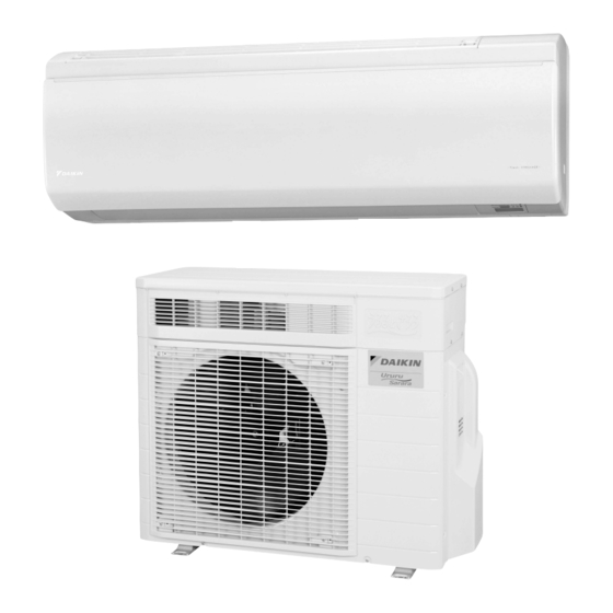
Wall Mounted Type E-Series
Brand:
Daikin
| Category:
Inverter
| Size: 5 MB
Table of Contents
Table of Contents
3
Introduction
6
Safety Cautions
6
Used Icons
10
Part 1 List of Functions
11
Functions
12
Part 2 Specifications
14
Specifications
15
Part 3 Printed Circuit Board Connector Wiring Diagram
19
Indoor Unit
20
Outdoor Unit
23
Part 4 Function and Control
24
Main Functions
25
Temperature Control
25
Frequency Principle
25
Airflow Direction Control
27
Fan Speed Control for Indoor Unit
30
Thermostat Control
31
URURU" HUMIDIFYING / HUMID HEATING Operation
32
SARARA" DRYING / DRY COOLING Operation
40
AUTO Operation
42
MOISTURIZING Operation
43
FLASH STREAMER AIR PURIFYING Operation
44
FRESH AIR SUPPLY VENTILATION Operation
46
Home Leave Ventilation
47
TIMER Operation
48
NIGHT SET Mode
49
COMFORT SLEEP Operation
50
POWERFUL Operation
52
MOLD PROOF Operation
53
MOLD SHOCK out Operation
55
Information Display
58
Multi-Colored Indicator Lamp
59
Monitor Brightness Setting
59
Child Proof Lock Setting
59
Clock Setting
60
Filter Cleaning Indicator
60
Other Functions
61
Table for Special Modes
62
Control Specification
64
Frequency Control
64
Controls at Mode Changing / Start-Up
66
Discharge Pipe Temperature Control
68
Input Current Control
69
Freeze-Up Protection Control
70
Heating Peak-Cut Control
70
Draft Prevention Control (Hot-Start Function)
71
Dew Prevention Control
71
Outdoor Fan Control
72
Liquid Compression Protection Function
72
Defrost Control
73
Electronic Expansion Valve Control
74
Part 5 Remote Controller
77
Ftxr28/42/50Ev1B9
78
Part 6 Service Diagnosis
81
Convenient Service Check Function
83
Indoor Unit
83
Outdoor Unit
83
Troubleshooting
84
Error Codes and Description
84
Air Conditioner Does Not Run
85
Air Conditioner Runs but Does Not Cool (Heat) the Room
88
When Operation Starts, Safety Breaker Works
90
Air Conditioner Makes Big Noise and Vibration
92
Air Is Not Humidified Enough
93
Lights-Out of Microcomputer Status Lamp
95
Indoor Unit PCB Abnormality
96
Freeze-Up Protection Control or Heating Peak-Cut Control
97
Fan Motor (DC Motor) or Related Abnormality
99
Streamer Unit Abnormality
101
Thermistor or Related Abnormality (Indoor Unit)
103
Front Panel Open / Close Abnormality
104
Humidity Sensor Abnormality
105
Refrigerant Shortage
106
Low-Voltage Detection or Over-Voltage Detection
108
Signal Transmission Error (between Indoor Unit and Outdoor Unit)
110
Outdoor Unit PCB Abnormality or Communication Circuit Abnormality
111
Signal Transmission Error on Outdoor Unit PCB
114
Unspecified Voltage (between Indoor Unit and Outdoor Unit)
115
Incomplete Setting for Hose Length
116
Outdoor Unit PCB Abnormality
117
OL Activation (Compressor Overload)
118
Compressor Lock
120
DC Fan Lock
121
Input Overcurrent Detection
122
Four Way Valve Abnormality
123
Discharge Pipe Temperature Control
125
High Pressure Control in Cooling
126
Compressor System Sensor Abnormality
127
Damper Abnormality
128
Position Sensor Abnormality
129
DC Voltage / Current Sensor Abnormality
131
Thermistor or Related Abnormality (Outdoor Unit)
132
Electrical Box Temperature Rise
134
Radiation Fin Temperature Rise
136
Output Overcurrent Detection
138
Fan Motor System Abnormality / Fan Lock
140
Heater Wire Abnormality
141
Humidifying Thermistor Abnormality / Humidifying Heater Temperature Abnormality
142
Check
144
Thermistor Resistance Check
144
Fan Motor Connector Output Check
145
Humidity Sensor Check
145
Power Supply Waveforms Check
145
Electronic Expansion Valve Check
146
Four Way Valve Performance Check
147
Inverter Units Refrigerant System Check
148
Inverter Analyzer Check
148
Rotating Pulse Check on Outdoor Unit PCB
150
Installation Condition Check
151
Discharge Pressure Check
151
Outdoor Fan System Check
152
Main Circuit Short Check
152
Power Module Check
153
Dehumidifying Solenoid Valve Check
154
Part 7 Trial Operation and Field Settings
155
Pump down Operation
156
Forced Cooling Operation
157
Trial Operation
158
Field Settings
159
Humidifying Hose Length Setting
159
When 2 Units Are Installed in 1 Room
160
Jumper Settings
160
Silicon Grease on Power Transistor / Diode Bridge
161
Part 8 Appendix
162
Piping Diagrams
163
Indoor Unit
163
Outdoor Unit
163
Wiring Diagrams
164
Indoor Unit
164
Outdoor Unit
164
Removal Procedure (Booklet No.)
165
Revision History
166
Advertisement
Advertisement
Related Products
Daikin SiEN04-604
Daikin SiBE81-909
Daikin SiBE07-618_D
Daikin SiBE041010
Daikin Si001554EC
Daikin SiUS041638EA
Daikin Siesta ARX-JV
Daikin Si12-992
Daikin Siesta ARXF-C
Daikin Siesta ATXP-M
Daikin Categories
Air Conditioner
Heat Pump
Chiller
Remote Control
Air Handlers
More Daikin Manuals
Login
Sign In
OR
Sign in with Facebook
Sign in with Google
Upload manual
Upload from disk
Upload from URL