Table of Contents
Advertisement
"Graphics and specfications may change without notice".
Specifications
Wingspan----------------------------------------- 78.7 in--------------------------- 200cm.
Wing area----------------------------------------- 906.8 sq.in--------------- 58.5 sq.dm.
Approximate flying weight---------------------7.5- 9.3 lbs----------------3.4 - 4.2kg.
Length---------------------------------------------- 51.1in------------------------- 129.8cm.
Recommended engine size---------------- .61 - .75 cu.in---------------- 2-stroke.
Radio System required 4 channels with 6 servos
Flying skill level Intermediate/advanced.
Kit features.
•
Ready-made—minimal assembly & finishing required.
•
Ready-covered covering.
•
Photo-illustrated step-by-step Assembly Manual.
Made in Vietnam.
ASSEMBLY MANUAL
.82 - .91cu.in-----------------4-troske.
MS: 87
Advertisement
Table of Contents

Related Manuals for Seagull Models Piper Cub


Summary of Contents for Seagull Models Piper Cub
-
Page 1: Specifications
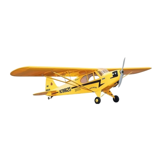
MS: 87 ASSEMBLY MANUAL “Graphics and specfications may change without notice”. Specifications Wingspan----------------------------------------- 78.7 in--------------------------- 200cm. Wing area----------------------------------------- 906.8 sq.in--------------- 58.5 sq.dm. Approximate flying weight---------------------7.5- 9.3 lbs----------------3.4 - 4.2kg. Length---------------------------------------------- 51.1in------------------------- 129.8cm. Recommended engine size---------------- .61 - .75 cu.in---------------- 2-stroke. .82 - .91cu.in-----------------4-troske. - Page 2 CODE SEA 87 INTRODUCTION. Thank you for choosing the PIPER CUB ARTF by SEAGULL MODELS. The PIPER CUB was designed with the intermediate/advanced sport scale in mind. It is a semi scale airplane which is easy to fly and quick to assemble. The airframe is conventionally built using balsa, plywood to make it stronger than the average ARTF , yet the design allows the aeroplane to be kept light.
-
Page 3: Hinging The Ailerons
Please trial fit all parts. Make sure you have the and aileron. correct parts and that they fit and are aligned properly before gluing! This will ensure proper assembly as the PIPER CUB is made from T- pin. natural materials and minor adjustments may have to be made. -
Page 4: Hinging The Rudder
Instruction Manual PIPER CUB _ CODE SEA 87 8) After both ailerons are securely hinged, TURNBUCKLE INSTALLATION. firmly grasp the wing panel and aileron to make sure the hinges are securely glued and Washer. Turnbuckle. cannot be pulled out. Do this by carefully applying medium pressure, trying to separate the aileron from the wing panel. - Page 5 www.seagullmodels.com Wing. Aileron. Installing the turnbuckle for tail strut of hori- zontal fin as same as pictures below. Tail fin bottom. Turnbuckle. ELEVATOR CONTROL HORN. Install the elevator control horn using the same method as with the aileron control horns. 2 sets.
-
Page 6: Rudder Control Horn
Instruction Manual PIPER CUB _ CODE SEA 87 Elevator control horn. Rudder control horn. RUDDER CONTROL HORN. Rudder control horn: Using the same tectniques used aileron control ENGINE MOUNT INSTALLATION. horn. See picture below. See pictures below.Make yourself the 2 sets. -
Page 7: Installing The Stopper Assembly
www.seagullmodels.com INSTALLING THE STOPPER ASSEMBLY. Vent tube. Fuel pick up tube. 1) Using a modeling knife, carefully cut off the rear portion of one of the 3 nylon tubes leaving 1/2” protruding from the rear of the Fuel fill tube. stopper. -
Page 8: Wheel Installation
Instruction Manual PIPER CUB _ CODE SEA 87 Blow through one of the lines to ensure the fuel lines have not become kinked in- side the fuel tank compartment. Air should Fuel tank. flow through easily. WHEEL INSTALLATION. C/A glue. -
Page 9: Installing The Landing Gear
www.seagullmodels.com 3) A drop of C/A glue on the wheel collar screws will help keep them from coming lose during operation. Repeat the process for the other wheel. INSTALLING THE LANDING GEAR Wheel M2 x 8mm. Fairing. 1.5mm diameter. 1.5mm diametter. MOUNTING THE ENGINE. -
Page 10: Cowling Installation
Instruction Manual PIPER CUB _ CODE SEA 87 COWLING INSTALLATION. 1) Slide the fiberglass cowl over the en- gine and line up the back edge of the cowl with the marks you made on the fuselage then trim and cut. - Page 11 www.seagullmodels.com 2) While keeping the back edge of the 1.5mm were cowl flush with the marks, align the front of (needle valve). the cowl with the crankshaft of the engine. The front of the cowl should be positioned so the crankshaft is in nearly the middle of the cowl opening.
-
Page 12: Installing The Switch
Instruction Manual PIPER CUB _ CODE SEA 87 INSTALLING THE SWITCH. Loctite secure. Adjustable Servo Install the switch into the precut hole in the connector. side of fuselage. Servo arm. 1 pcs. Elevator servo . Throttle servo arm. Rudder servo . -
Page 13: Installing The Vertical Stabilizer
www.seagullmodels.com When cutting through the covering to re- move it, cut with only enough pressure to only cut through the covering itself. Cutting into the balsa structure may weaken it. Remove covering. Epoxy Remove covering. INSTALLING THE VERTICAL STABILIZER. Put the vertical stabilizer into the in the top of the horizontal fin. -
Page 14: Installing The Aileron Servos
Instruction Manual PIPER CUB _ CODE SEA 87 INSTALLING THE AILERON SERVOS. String. Small weight. Servos. Small weight. Aileron Servo electric wire. Servo. Thread. Wing rib. Wing. Small Weight. Small Weight. String. String. Attach the string to the servo lead and carefully thread it though the wing. - Page 15 www.seagullmodels.com ELEVATOR - RUDDER PUSHROD INSTALLATION. Wing. Rudder control horn. M2 lock nut. Aileron. Elevator control horn. Repeat the procedure for the other wing. Elevator and rudder pushrods assembly follow pictures below. M2 clevis. M2 Lock nut. Attach to elevator - rudder control horn. Attach to servo arm in fuselage.
- Page 16 Instruction Manual PIPER CUB _ CODE SEA 87 Bottom. Control horn. Elevator Pushrod. 15mm. M2 lock nut. Metal clevis. Elevator pushrod. Fuselage bottom. Rudder pushrod. Throttle. Elevator. Bottom. Alumium trap. Rudder. Elevator. M3 x 10mm. INSTALLING TAIL STRUT SUPPORT The tail strut system assembly follow pic- tures below.
-
Page 17: Mounting The Tail Wheel
www.seagullmodels.com Horizontal Fin. Vertical Fin. 122mm. INSTALLING THE BATTERY-RECEIVER. 1) Plug the six servo leads and the switch lead into the receiver. Plug the battery pack lead into the switch also. 2) Wrap the receiver and battery pack in the protective foam rubber to protect them from vibration. - Page 18 Instruction Manual PIPER CUB _ CODE SEA 87 Antenna. ATTACHMENT WING-FUSELAGE. Attach the aluminium tube into fuselage. Wing bolt. Aluminum tube. M3x50mm. Wing tube. C/A glue. Insert two wing panels as pictures below. Plastic Screw. 4.5-5mm diameter screw.
-
Page 19: Installing The Wing Strut
www.seagullmodels.com M3x50mm. M4x25mm. Turnbuckle. M3x50mm. 60mm. INSTALLING THE WING STRUT. 85mm. Parts requirement.See pictures below. -
Page 20: Control Throws
7.5cm. CONTROL THROWS. 1) We highly recommend setting up the PIPER CUB using the control throws listed at right. We have listed control throws for both Low Rate (initial test flying/sport flying) and High Rate (aerobatic flying). - Page 21 2) Check every bolt and every glue joint 8) Properly balance the propeller. An out in the PIPER CUB to ensure that everything of balance propeller will cause excessive vi- is tight and well bonded. bration which could lead to engine and/or air- 3) Double check the balance of the air- frame failure.
Need help?
Do you have a question about the Piper Cub and is the answer not in the manual?
Questions and answers