Table of Contents
Advertisement
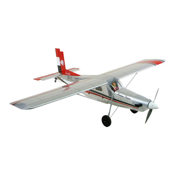
Pilatus PC-6
"Graphics and specifications may change without notice".
Specifications
Wing span-------------------------------------- 63 in-------------------------------------- 160cm.
Wing area-------------------------------------- 722.3 sq.in-------------------------46.6 sq.dm.
Approximate flying weight------------------6.2-7.1 lbs----------------------------2.8-3.2kg.
Length------------------------------------------ 53.7in----------------------------------- 136.3cm.
Recommended engine size-------------- .46-.55cu.in---------------------------- 2-stroke.
ELECTRIC CONVERSION : OPTIONAL.
Recommended R/C --------------------------------------------- 4 channels with 5 servos.
Flying skill level ---------------------------------------------------- Advanced/Intermediate.
Kit features.
•
Ready-made—minimal assembly & finishing required.
•
Ready-covered covering.
•
Photo-illustrated step-by-step Assembly Manual.
Made in Vietnam.
Porter
ASSEMBLY MANUAL
.72-.82cu.in-----------------------------4-stroke.
MS: 107
Advertisement
Table of Contents

Subscribe to Our Youtube Channel
Related Manuals for Seagull Models Pilatus PC-6 Porter


Summary of Contents for Seagull Models Pilatus PC-6 Porter
- Page 1 Pilatus PC-6 Porter MS: 107 ASSEMBLY MANUAL “Graphics and specifications may change without notice”. Specifications Wing span-------------------------------------- 63 in-------------------------------------- 160cm. Wing area-------------------------------------- 722.3 sq.in-------------------------46.6 sq.dm. Approximate flying weight------------------6.2-7.1 lbs----------------------------2.8-3.2kg. Length------------------------------------------ 53.7in----------------------------------- 136.3cm. Recommended engine size-------------- .46-.55cu.in---------------------------- 2-stroke. .72-.82cu.in-----------------------------4-stroke. ELECTRIC CONVERSION : OPTIONAL.
-
Page 2: Fuselage Assembly
Flying the PC-6 is simply a joy. This instruction manual is designed to help you build a great flying aeroplane. Please read this manual thoroughly before starting assembly of your PC-6 . Use the parts listing below to identify all parts. -
Page 3: Hinging The Ailerons
This will ensure proper Hinge. assembly as the PC-6 is made from natural materials and minor adjustments may have to be made. The paint and plastic parts used in this kit are fuel proof. -
Page 4: Hinging The Rudder
Instruction Manual PC-6 _ CODE SEA 107 5) Turn the wing panel over and deflect the HINGING THE RUDDER. aileron in the opposite direction from the opposite side. Apply thin C/A glue to each Glue the rudder hinges in place using the hinge, making sure that the C/A penetrates into same techniques used to hinge the ailerons. - Page 5 www.seagullmodels.com ELEVATOR CONTROL HORN. AILERON CONTROL HORN Install the elevator control horn using the Aileron control horn: See pictures below same method as with the aileron control horns. 2 sets. 2 sets. 3x40mm. 3x35mm. CONTROL HORN M3 SCREW CONTROL HORN M3. Epoxy.
-
Page 6: Rudder Control Horn
Instruction Manual PC-6 _ CODE SEA 107 RUDDER CONTROL HORN. ENGINE MOUNT INSTALLATION. Rudder control horn: See pictures below.Make yourself the Using the same tectniques used aileron control template of your engine on paper. horn. See picture below. 2 sets. - Page 7 www.seagullmodels.com WHEEL AND WHEEL PANTS INSTALLATION. 1) Assemble and mounting the wheel pants as shown in the following pictures. M3 x 15mm M3 x 10mm...
-
Page 8: Installing The Aileron Servos
Instruction Manual PC-6 _ CODE SEA 107 3) A drop of C/A glue on the wheel collar screws will help keep them from coming lose during operation. Repeat the process for the other wheel. INSTALLING THE AILERON SERVOS. Servos. Small weight. -
Page 9: Installing The Switch
www.seagullmodels.com INSTALLING THE SWITCH. Wing. Install the switch into the precut hole in the side of fuselage. Aileron. INSTALLING THE FUSELAGE SERVO. Because the size of servos differ, you may need to adjust the size of the precut open- ing in the mount. The notch in the sides of the mount allow the servo lead to pass through. -
Page 10: Installing The Stopper Assembly
Instruction Manual PC-6 _ CODE SEA 107 Repeat the procedure for the other wing. Vent tube. Fuel pick up tube. INSTALLING THE STOPPER ASSEMBLY. 1) Using a modeling knife, carefully cut off the rear portion of one of the 3 nylon tubes leaving 1/2”... -
Page 11: Fuel Tank Installation
www.seagullmodels.com 5) With the stopper assembly in place, the weighted pick-up should rest away from the rear of the tank and move freely inside the tank. The top of the vent tube should rest just Vent tube. below the top of the tank. It should not touch the top of the tank. -
Page 12: Cowling Installation
Instruction Manual PC-6 _ CODE SEA 107 4) Bolt the engine to the engine mount using the four machine screws. Double check that all the screws are tight before proceeding. 1.5mm diameter. Trim and cut. Pushrod wire. Trim and cut. - Page 13 www.seagullmodels.com Epoxy. Electric Conversion (Ep Power) (OPTION). Balsa block. Blink nut. Epoxy. Epoxy. 115mm.
-
Page 14: Spinner Installation
Instruction Manual PC-6 _ CODE SEA 107 4mm. M3x15mm. Battery. Blink nut. Balsa block. SPINNER INSTALLATION. Install the spinner backplate, propeller and spinner cone. The propeller should not touch any part of the spinner cone. If it does, use a... -
Page 15: Installing The Horizontal Stabilizer
www.seagullmodels.com Epoxy. INSTALLING THE HORIZONTAL Epoxy. STABILIZER. Draw center line. Remove covering. Pen. When cutting through the covering to re- move it, cut with only enough pressure to only cut through the covering itself. Cutting into the balsa structure may weaken it. Remove covering. -
Page 16: Installing The Vertical Stabilizer
Instruction Manual PC-6 _ CODE SEA 107 INSTALLING THE VERTICAL STABILIZER. Epoxy. Put the vertical stabilizer into the in the top of the horizontal fin. The bottom edge of the sta- bilizer should also be firmly pushed against the top of the horizontal stabilizer. - Page 17 www.seagullmodels.com INSTALLATION THE PUSHROD. Cut. 90mm. Snap keeper. Servo arm. 90mm. 8mm. Snap keeper. ELEVATOR - RUDDER PUSHROD Wing. INSTALLATION. Aileron. Control horn.
- Page 18 Instruction Manual PC-6 _ CODE SEA 107 Repeat the procedure for the other wing. Elevator and rudder pushrods assembly follow pictures below. M2 clevis. M2 Lock nut. Attach to elevator - rudder control horn. Attach to servo arm in fuselage.
-
Page 19: Mounting The Tail Wheel
www.seagullmodels.com MOUNTING THE TAIL WHEEL. See pictures below. M2 lock nut. Cut. 120mm. Elevator pushrod. Control horn. M2 lock nut. Rudder Pushrod. Metal clevis. M3x12mm. - Page 20 Instruction Manual PC-6 _ CODE SEA 107 Metal Clevis. M2 lock nut.
-
Page 21: Installing The Battery
www.seagullmodels.com INSTALLING THE BATTERY. C/A glue. Plactic screw ATTACHMENT WING-FUSELAGE. Attach the aluminium tube into fuselage. INSTALLING THE RECEIVER. Insert two wing panels as pictures below. Receiver. C/A glue. Wing bolt. Cut. - Page 22 Instruction Manual PC-6 _ CODE SEA 107 Plastic Screw. Plastic screw. M3x6mm.
-
Page 23: Control Throws
8cm. 2) Check every bolt and every glue joint in the PC-6 to ensure that everything is tight and well bonded. 3) Double check the balance of the air- plane. Do this with the fuel tank empty.
Need help?
Do you have a question about the Pilatus PC-6 Porter and is the answer not in the manual?
Questions and answers