Seagull Models PC-9 Assembly Manual
Hide thumbs
Also See for PC-9:
- Assembly manual (25 pages) ,
- Assembly manual (20 pages) ,
- Instruction manual (23 pages)
Table of Contents
Advertisement
Quick Links
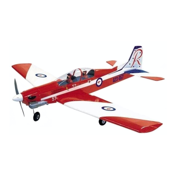
PC - 9
"Graphics and specifications may change without notice".
Specifications:
Wing span-------------------------------------------------- 63.0 in--------------------------------------- 160cm.
Wing area---------------------------------------------------647.9sq.in---------------------------- 41.8 sq.dm.
Approximate flying weight--------------------------84-9.3 lbs-------------------------------------3.8-4.2 kg.
Length------------------------------------------------------ 58.3in---------------------------------------- 148cm.
Recommended engine size-------------------------.75-.91cu.in------------------------------------- 2-stroke.
ELECTRIC CONVERSION : OPTIONAL.
Recommended R/C --------------------------------------------- 4 channels with 7 servos.
Flying skill level ---------------------------------------------------- Advanced/Intermediate.
Kit features.
•
Ready-made—minimal assembly & finishing required.
•
Ready-covered—including decals, trim & covering.
•
Factory-installed pushrod.
•
Photo-illustrated step-by-step Assembly Manual.
ASSEMBLY MANUAL
.91-1.00cu.in--------------------------------------4-stroke.
MS: SEA 103
Made in Vietnam.
Advertisement
Table of Contents

Related Manuals for Seagull Models PC-9


Summary of Contents for Seagull Models PC-9
- Page 1 PC - 9 MS: SEA 103 ASSEMBLY MANUAL “Graphics and specifications may change without notice”. Specifications: Wing span-------------------------------------------------- 63.0 in--------------------------------------- 160cm. Wing area---------------------------------------------------647.9sq.in---------------------------- 41.8 sq.dm. Approximate flying weight--------------------------84-9.3 lbs-------------------------------------3.8-4.2 kg. Length------------------------------------------------------ 58.3in---------------------------------------- 148cm. Recommended engine size-------------------------.75-.91cu.in------------------------------------- 2-stroke. .91-1.00cu.in--------------------------------------4-stroke. ELECTRIC CONVERSION : OPTIONAL. Recommended R/C --------------------------------------------- 4 channels with 7 servos.
- Page 2 . Flying the PC-9 is simply a joy. This instruction manual is designed to help you build a great flying aeroplane. Please read this manual thoroughly before starting assembly of your PC-9 . Use the parts listing below to identify all parts.
-
Page 3: Hinging The Ailerons
Please trial fit all parts. Make sure you have the correct parts and that they fit and are aligned properly before gluing! Hinge. This will ensure proper assembly as PC-9 is made from natural materials and minor adjustments may have to be made. The paint and... -
Page 4: Hinging The Rudder
Instruction Manual. PC-9 _ CODE SEA 103 HINGING THE RUDDER. Glue the rudder hinges in place using the same techniques used to hinge the ailerons. C/A glue. 5) Turn the wing panel over and deflect the aileron in the opposite direction from the opposite side. - Page 5 www.seagullmodels.com Wing bottom. Aileron. Aileron control horn ELEVATOR CONTROL HORN. Install the elevator control horn using the Masking tape. same method as with the aileron control horns. 2 sets. AILERON CONTROL HORN. 2 sets. 3mmx35mm. M3x35mm CONTROL HORN M3 CONTROL HORN M3 SCREW.
-
Page 6: Rudder Control Horn
Instruction Manual. PC-9 _ CODE SEA 103 Elevator control horn. Rudder control horn. RUDDER CONTROL HORN. SERVO GEAR INSTALLATION. Rudder control horn: Using the same techniques used aileron Metal connector. control horn. See picture below. 1 sets. 25mm. Servo arm. -
Page 7: Gear Installation
www.seagullmodels.com 110mm. 120mm. Remove covering. Metal clevis. Pushrod. M3 lock. M3x25mm Electric wire. Wing bottom. GEAR INSTALLATION. M3x25mm. -
Page 8: Wing Assembly
Instruction Manual. PC-9 _ CODE SEA 103 C/A. Open Position Servo arm. Close Position. 25mm. 12mm. servo arm. WING ASSEMBLY. Aluminum tubes diameter = 19x806mm. C/A glue. Masking tape. - Page 9 www.seagullmodels.com Epoxy. Epoxy. Masking tape.
-
Page 10: Engine Mount Installation
Instruction Manual. PC-9 _ CODE SEA 103 3) Carefully bend the second nylon tube up at a 45º angle. This tube is the vent tube. ENGINE MOUNT INSTALLATION. See pictures below.Make yourself the template of your engine on paper. M4x30mm. -
Page 11: Fuel Tank Installation
www.seagullmodels.com 5) Test fit the stopper assembly into the Fuel tank. tank. It may be necessary to remove some of the flashing around the tank opening using a modeling knife. If flashing is present, make sure none falls into the tank. 6) With the stopper assembly in place, the weighted pickup should rest away from the rear of the tank and move freely inside the... -
Page 12: Mounting The Engine
Instruction Manual. PC-9 _ CODE SEA 103 20mm 135mm. 4.2mm. MOUNTING THE ENGINE. 1) Install the pushrod housing through the predrilled hole in the firewall and into the servo compartment. The pushrod housing should protrude 1/4" out past the front of the firewall. - Page 13 www.seagullmodels.com COWLING Needle valve. Trim and cut. Machine Screw M3x10mm. Electric Conversion (Ep Power) Trim and cut. (OPTION). Epoxy. Machine Screw M3x10mm.
- Page 14 Instruction Manual. PC-9 _ CODE SEA 103 Blind nut. Epoxy. Balsa block. M4 x 15mm. Electric motor. Epoxy. Balsa block. Epoxy. 135mm. Battery. M3x15mm. Epoxy. 5.2mm.
-
Page 15: Spinner Installation
www.seagullmodels.com SPINNER INSTALLATION. Install the spinner backplate, propeller and spinner cone. The propeller should not touch any part of the spinner cone. If it does, use a sharp modeling knife and carefully trim away the spinner cone where the propeller comes in contact with it. - Page 16 Instruction Manual. PC-9 _ CODE SEA 103 AILERON PUSHROD HORN INSTALLATION Cut. Snap keeper. Servo arm. Snap keeper. 8mm. Wing. Cut . M2 lock nut. Aileron. INSTALLING THE FUSELAGE SERVO. Stearing servo. Rudder. Elevator servo . Throttle servo arm.
-
Page 17: Installing The Switch
www.seagullmodels.com INSTALLING THE SWITCH. Remove the covering. Install the switch into the precut hole in the side of fuselage. Switch. Epoxy. Cut. Epoxy. INSTALLING THE HORIZONTAL STABILIZER. Pen. - Page 18 Instruction Manual. PC-9 _ CODE SEA 103 Pen. Masking tape. Cut. Remove the covering. INSTALLING THE VERITICAL STABILIZER. Cut. Epoxy.
- Page 19 www.seagullmodels.com M3 lock nut. Control horn. Elevator Pushrod. Metal clevis. C/A. ELEVATOR PUSHROD HORN INSTALLATION. ELEVATOR PUSHROD HORN INSTALLATION. 1) Thread one clevis and M3 lock nut on to each elevator control rod. Thread the horns on until they are flush with the ends of the con- trol rods.
- Page 20 Instruction Manual. PC-9 _ CODE SEA 103 Pushrod . M lock Metal Levis. Elevator . Stearing servo. Throttle servo arm. Rudder servo.
- Page 21 www.seagullmodels.com Wheel. Stearing servo. Rudder. Throttle servo arm. MOUNTING THE NOSE WHEEL. See picture below. M3x25mm. 1.8mmx41mm. Wheel. 2.6mmx33.5mm. M3 lock nut. Landing gear. M2 lock nut.
-
Page 22: Installing The Battery
Instruction Manual. PC-9 _ CODE SEA 103 INSTALLTION PILOT. Stearing sevor. Throttle. M2x6mm. Rudder. INSTALLING THE BATTERY. Battery. 165mm. Plastic Screw. -
Page 23: Installing The Receiver
www.seagullmodels.com ATTACHMENT WING - FUSELAGE. 8mm. 8mm. Wing bolt. M2 x 6mm. INSTALLING THE RECEIVER. 1) Plug the servo leads and the switch lead into the receiver. Plug the battery pack C/A glue. lead into the switch also. 2) Wrap the receiver and battery pack in the protective foam rubber to protect them from vibration. -
Page 24: Control Throws
Instruction Manual. PC-9 _ CODE SEA 103 BALANCING. 1) It is critical that your airplane be balanced correctly. Improper balance will cause your plane to lose control and crash. The center of gravity is located 70mm back from the lead- ing edge of the wing, measured at the wing root. -
Page 25: Flight Preparation
B) Plug in your radio system per the manufacturer's instructions and turn every- 2) Check every bolt and every glue joint in the PC-9 to ensure that everything is tight and thing on. well bonded. C) Check the elevator first. Pull back on 3) Double check the balance of the air the elevator stick.
Need help?
Do you have a question about the PC-9 and is the answer not in the manual?
Questions and answers