Table of Contents
Advertisement
Quick Links
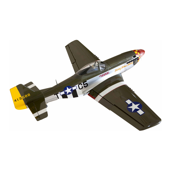
MUSTANG P-51
Hand-made Almost Ready to Fly R/C Model Aircraft
Specifications
Wingspan---------------------------------------- 60.5 in----------------------- 153.7cm.
Wing area------------------------------------- 661sq.in------------------ 42.65 sq.dm.
Weight-----------------------------------------5.5-6.2lbs-----------------------2.5-2.8kg.
Length----------------------------------------------- 50 in-------------------------- 127cm.
Recommended engine size--------------.40-.46 cu.in------------------ 2-stroke.
Radio System required 4 channel with 6 digital servos.
Flying skill level Intermediate/advanced.
Kit features.
•
Ready-made—minimal assembly & finishing required.
•
Ready-covered covering.
•
Photo-illustrated step-by-step Assembly Manual.
Made in Vietnam.
ASSEMBLY MANUAL
.52 cu.in------------------4-stroke.
Advertisement
Table of Contents

Related Manuals for Seagull Models MUSTANG P-51


Summary of Contents for Seagull Models MUSTANG P-51
- Page 1 MUSTANG P-51 Hand-made Almost Ready to Fly R/C Model Aircraft ASSEMBLY MANUAL Specifications Wingspan---------------------------------------- 60.5 in----------------------- 153.7cm. Wing area------------------------------------- 661sq.in------------------ 42.65 sq.dm. Weight-----------------------------------------5.5-6.2lbs-----------------------2.5-2.8kg. Length----------------------------------------------- 50 in-------------------------- 127cm. Recommended engine size--------------.40-.46 cu.in------------------ 2-stroke. .52 cu.in------------------4-stroke. Radio System required 4 channel with 6 digital servos.
- Page 2 The airframe is conventionally built using balsa, plywood to make it stronger than the average ARTF , yet the design allows the aeroplane to be kept light. You will find that most of the work has been done for you already.Flying the MUSTANG P-51 is simply a joy.
- Page 3 Please trial fit all parts. Make sure you have the correct parts and that they fit and are aligned properly before gluing! This will ensure proper as- sembly as the MUSTANG P-51 is made from natural materials and minor adjustments may have to be made.
-
Page 4: Hinging The Ailerons
MUSTANG P-51. Instruction Manual. 4)Deflect the aileron and completely HINGING THE AILERONS. saturate each hinge with thin C/A glue. The ailerons front surface should lightly contact the Note: The control surfaces, including the wing during this procedure. Ideally, when the ailerons, elevators, and rudder, are hinges are glued in place, a 1/64”... -
Page 5: Wing Assembly
www.seagullmodels.com 8) After both ailerons are securely hinged, WING ASSEMBLY. firmly grasp the wing panel and aileron to NOTE: We highly recommend using 30 make sure the hinges are securely glued and minute epoxy as it is stronger and cannot be pulled out. Do this by carefully provides more working time, allowing applying medium pressure, trying to separate the builder to properly align the parts. -
Page 6: Installing The Aileron Servos
MUSTANG P-51. Instruction Manual. Expoxy. Carefully slide the two wing halves together and firmly press them together, allowing the excess epoxy to run out. There should not be any gap in the wing halves. Use rubbing Remove covering. alcohol and a paper tower to clean up any excess epoxy. - Page 7 www.seagullmodels.com Because the size of servos differ, you may need to adjust the size of the precut opening in the mount. The notch in the sides of the mount allow the servo lead to pass through. Using a small weight ( Weighted fuel pick-up ) and thread, feed the string through works well...
-
Page 8: Installing The Aileron Linkage
MUSTANG P-51. Instruction Manual. 3) Position the aileron horn on the bottom side of aileron. The clevis attachment holes should be positioned over the hinge line. Control Horn. Plastic tape. Mounting Screws. Mounting Plate. AILERON LINKAGE. 4) Using a 1mm drill bit and the control horns as a guide, drill the mounting holes INSTALLING THE AILERON LINKAGE. -
Page 9: Main Landing Gear Installation
www.seagullmodels.com Wing pannel. Aileron. Repeat the procedure for the other aileron servo. MAIN LANDING GEAR Clevis. INSTALLATION. INSTALLING THE MAIN GEAR WIRES. Pen. Aileron torque rod. 3mm x 10mm. Cut. 1) Using a modeling knife, remove the cov- ering from over the two main gear mounting slots located in the bottom of the wing. -
Page 10: Installing The Main Gear Wheels
MUSTANG P-51. Instruction Manual. INSTALLING THE MAIN GEAR WHEELS. The straps should be located equal dis- tance from the inside and outside ends 1) Slide one wheel collar with 3mm x of the wire. 6mm set screw onto each axle. Push the wheel collars on as far as they will go and tighten the set screws. -
Page 11: Installing The Stopper Assembly
www.seagullmodels.com C/A glue. Repeat the procedure for the other main gear wheel. FUEL TANK. Vent tube. Fuel Pickup INSTALLING THE STOPPER ASSEMBLY. Tube. Fuel Fill Tube. Carefully use a lighter or heat gun to permenently set the angle of the vent tube. Important: When the stopper assembly is in- stalled in the tank, the top of the vent tube should rest just below the top surface of the... -
Page 12: Installing The Fuel Tank
MUSTANG P-51. Instruction Manual. Pull. Blow through the tubes to make sure the lines have not become kinked during installation. Cut. Fuel tank. Attach the silicone fuel and pressure pipes to the tank. The lower pipe is the ‘feed’ and the upper two the ‘pressure and fill’. - Page 13 www.seagullmodels.com 11.2cm. 3mm X 25mm. 2) Place your engine onto the engine mount. Adjust the engine is centered of the edges of the engine case. 3) When you are satisfied with the align- ment, mark the locations of the engine mounting.
- Page 14 MUSTANG P-51. Instruction Manual. 2) While keeping the back edge of the cowl flush with the marks, align the front of the cowl with the crankshaft of the engine. The front of the cowl should be positioned so the crankshaft is in nearly the middle of the cowl opening.
-
Page 15: Installing The Spinner
www.seagullmodels.com Needle valve. Glue attached. 3mmX10mm. INSTALLING THE SWITCH. INSTALLING THE SPINNER. 1) Install the switch into the precut hole in the servo tray, in the fuselage, from the bot- tom. Use the two screws provided with the switch to secure it in place. Drill two 3/32” holes through the tray for the screws to pass through. -
Page 16: Horizontal Stabilizer
MUSTANG P-51. Instruction Manual. HORIZONTAL STABILIZER. 1) Using a ruler and a pen, locate the centerline of the horizontal stabilizer, at the trail- ing edge, and place a mark. Use a triangle and extend this mark, from back to front, across the top of the stabilizer. -
Page 17: Vertical Stabilizer Installation
www.seagullmodels.com Pen. After the epoxy has fully cured, re- 5) Remove the stabilizer. Using the lines move the masking tape or T-pins used to hold you just drew as a guide, carefully remove the the stabilizer in place. Carefully inspect the covering from between them using a model- glue joints. - Page 18 MUSTANG P-51. Instruction Manual. Vertical Stabilizer. Horizontal 90º Stabilizer. 3) While holding the vertical stabilizer firmly in place, use a pen and draw a line on each side of the vertical stabilizer where it Epoxy glue. meets the top of the fuselage.
-
Page 19: Control Horn Installation
www.seagullmodels.com Cut. CONTROL HORN INSTALLATION. 1) Locate the two nylon control horns, two nylon control horn backplates and four Cut. machine screws. 2) Position the elevator horn on the both side of elevator. The clevis attach- ment holes should be positioned over the hinge line. 2mmX20mm. - Page 20 MUSTANG P-51. Instruction Manual. ELEVATOR - RUDDER PUSHROD INSTALLATION. Elevator. 1) Elevator and rudder pushrods assembly follow pictures below. Switch. Control horn. Rudder. Elevator. Throttle. Pushrod. M2 lock nut. MOUNTING THE TAIL WHEEL BRACKET. 2) Connect the elevator and rudder servos to your radio’s receiver and turn on the sys-...
-
Page 21: Installing The Receiver And Battery
www.seagullmodels.com INSTALLING THE RECEIVER AND BATTERY. 1) Plug the six servo leads and the switch lead into the receiver. Plug the battery pack lead into the switch also. 2) Wrap the receiver and battery pack in the protective foam rubber to protect them from vibration. - Page 22 MUSTANG P-51. Instruction Manual. ATTACHMENT WING-FUSELAGE. Receiver. Battery. 4mmX20mm. Oil cooling part. Antenna tube. Antenna.
-
Page 23: Flight Preparation
We highly recommend setting up the C) Check the elevator first. Pull back on MUSTANG P-51 using the control throws the elevator stick. The elevator halves should listed at right. We have listed control throws move up. If it they do not, flip the servo re-... -
Page 24: Preflight Check
2) Check every bolt and every glue joint in the MUSTANG P-51 to ensure that every- thing is tight and well bonded. 3) Double check the balance of the air- plane. Do this with the fuel tank empty.
Need help?
Do you have a question about the MUSTANG P-51 and is the answer not in the manual?
Questions and answers