Seagull Models PC-9 Assembly Manual
Hide thumbs
Also See for PC-9:
- Assembly manual (25 pages) ,
- Instruction manual (23 pages) ,
- Assembly manual (26 pages)
Table of Contents
Advertisement
Hand-made
Hand-made Almost R
Hand-made
Hand-made
Hand-made
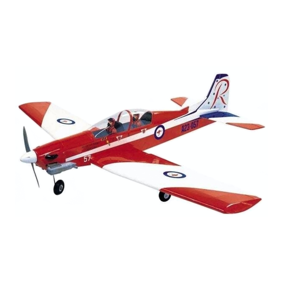
Specifications
Wingspan---------------------------------------60.63in, 1540mm.
Wing area--------------------------------610 sq.in, 37.04sq.dm.
Fuselage length--------------------------------43.7in, 1110mm.
Approximate flying weight---------5.5-5.95lbs, 2500-2700g.
Recommended engine size---------.40-.58 cu.in. 2-stroke.
----------------------------------------------.50-.72 cu.in. 4-stroke.
Recommended R/C-----------------------4 channel minimum.
Flying skill level-------------------------Intermediate/advanced.
Kit features.
•
Ready-made—minimal assembly & finishing required.
•
Factory-installed pushrods.
•
Comprehensive hardware pack including wheels, tank,
undercarriage & spinner.
•
Photo-illustrated step-by-step Assembly Manual.
PC-9
semi Scale ARF Model
Almost R
Almost R
Almost Read
Almost R
ead
ead
eady to F
ead
Aircraft
Aircraft
Aircraft
Aircraft
Aircraft
ASSEMBL
ASSEMBL
ASSEMBLY MANU
Y MANU
Y MANUAL
Y MANU
ASSEMBL
ASSEMBL
Y MANU
y to F
y to F
y to Fl l l l l y R/C Model
y to F
y R/C Model
y R/C Model
y R/C Model
y R/C Model
AL
AL
AL
AL
Additional items required.
Engine.
4 Channel or greater Radio Control system.
Glues.
Tools.
Starting Equipment.
MS:12
Made in Vietnam.
Advertisement
Table of Contents

Subscribe to Our Youtube Channel
Related Manuals for Seagull Models PC-9


Summary of Contents for Seagull Models PC-9
- Page 1 PC-9 semi Scale ARF Model Hand-made Hand-made Hand-made Almost R Hand-made Hand-made Almost R Almost R Almost R Almost Read eady to F y to F y to F y to F y to Fl l l l l y R/C Model...
-
Page 2: Fuselage Assembly
Flying the PC-9 is simply a joy. This instruction manual is designed to help you build a great flying aeroplane. Please read this manual thoroughly before starting assembly of your PC-9 . Use the parts listing below to identify all parts. -
Page 3: Hinging The Ailerons
This will ensure proper ! 1) Carefully remove the aileron from one of assembly as the PC-9 is made from the wing panels. Note the position of the hinges. natural materials and minor adjust- ments may have to be made. -
Page 4: Hinging The Elevator
PC-9 Instruction Manual. hinges are glued in place, a 1/64” gap or less will be maintained throughout the lengh of the aileron to the wing panel hinge line. Note: The hinge is constructed of a special material that allows the C/A to wick or... -
Page 5: Hinging The Rudder
www.seagullmodels.com HINGING THE RUDDER. Glue the elevator hinges in place using the same tectniques used to hinge the ailerons. Epoxy. Carefully slide the two wing halves together and firmly press them together, allowing the excess epoxy to run out. There should not be any gap in the wing halves. -
Page 6: Installing The Aileron Servos
PC-9 Instruction Manual. Thread. Remove covering. Small weight. Glue attached. INSTALLING THE AILERON SERVOS. ! 3) Attach servo lead to the aileron servo. Thread. Small Attach the string to the servo lead and care- weight. fully thread it though the wing. Once you have thread the lead throught the wing, remove the string so it can use for the other servo lead. -
Page 7: Aileron Linkage
www.seagullmodels.com AILERON LINKAGE. ! 1) Using a ruler & pen to draw a straight line as below picture. Thread. ! 4) Tape the servo lead to the wing to pre- Pen. vent it from falling back into the wing. Plastic tape. Straight line. -
Page 8: Installing The Main Gear Wires
PC-9 Instruction Manual. 4) Using a 1mm drill bit and the control 8) Make a 90-degree bend at the mark horns as a guide, drill the mounting holes and cut off the excess wire leaving 10mm past through the aileron halves. -
Page 9: Nose Gear Installation
www.seagullmodels.com ! 3) The landing gear wire is held in place ! 8) Slide one 60mm diameter wheel onto using two nylon landing gear straps and four each axle and push them up against the wheel 3mm x 12mm wood screws. collars. -
Page 10: Installing The Stopper Assembly
PC-9 Instruction Manual. FUEL TANK. Install the pushrod wire as shown. INSTALLING THE STOPPER ASSEMBLY. ! 1) Using a modeling knife, carefully cut Adjustable off the rear portion of one of the two nylon tubes Connector. leaving 1/2” protruding from the rear of the stopper. -
Page 11: Installing The Fuel Tank
www.seagullmodels.com ! 4) Carefully heat the vent tube using a INSTALLING THE FUEL TANK. heat gun or lighter to permanently set the angle of the tube. Pushrod wire. Vent tube. Fuel Pickup Tube. Fuel Fill Tube. When the stopper assembly is installed in Using a modeling knife, cut one length of the tank, the top of the vent tube should rest fuel line 20”... -
Page 12: Mounting The Engine
PC-9 Instruction Manual. Fuel tank. Vent tube. ! 5) Attach the Z-Bend in the pushrod wire to the throttle arm on the carburetor. You will need to remove the throttle arm from the car- buretor to be able to attach the Z-bend. When complete, reattach the throttle arm to the car- Fuel fill tube. - Page 13 www.seagullmodels.com ! 4) Remove the cowl. Using a 5/64” drill COWLING. bit, enlarge the holes in only the four cowl blocks. ! 5) Using a 1/8” drill bit. Enlarging the holes through the cowl will prevent the fiberglass from splitting when the mounting screws are installed.
-
Page 14: Installing The Spinner
PC-9 Instruction Manual. INSTALLING THE SWITCH. ! 1) Install the switch into the precut hole INSTALLING THE SPINNER. in the servo tray, in the fuselage, from the bot- tom. Use the two screws provided with the Install the spinner backplate, propeller switch to secure it in place. -
Page 15: Installing The Fuselage Servos
www.seagullmodels.com ! 3) Slide the stabilizer into place in the pre- INSTALLING THE FUSELAGE SERVOS. cut slot in the rear of the fuselage. The stabi- lizer should be pushed firmly against the front of the slot. ! 4) When you are satisfied with the align- ment, hold the stabilizer in place with T- pins or masking tape, but do not glue at this time. -
Page 16: Vertical Stabilizer Installation
PC-9 Instruction Manual. in the fuselage. Slide the stabilizer in place ! 2) Slide the vertical stabilizer into the slot and realign. Double check all of your mea- in the top of the fuselage. The rear edge of surements once more before the epoxy cures. -
Page 17: Control Horn Installation
www.seagullmodels.com ! 2) Position the two elevator horns on the bottom side of each elevator. The clevis at- tach- ment holes should be positioned over the hinge line. 2mm X 20mm. Remove covering. ! 5) Slide the vertical stabilizer back in place. -
Page 18: Installation
! 1) Plug the five servo leads and the switch leading edge of the wing, at the fuselage sides. lead into the receiver. Plug the battery pack Balance the PC-9 upside down with the fuel lead into the switch also. tank empty. -
Page 19: Control Throws
To ! 2) Check every bolt and every glue joint correct this, move the battery and receiver in the PC-9 to ensure that everything is tight forward orif this is not possible, stick weight and well bonded.
Need help?
Do you have a question about the PC-9 and is the answer not in the manual?
Questions and answers