Advertisement
Quick Links
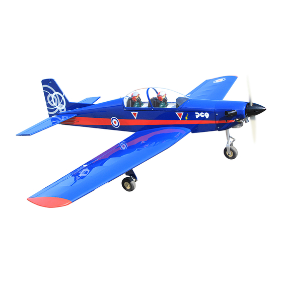
ASSEMBLY MANUAL
Specifications:
Wingspan--------------- 60.6 in------------------- 1540 mm.
Wing area--------------- 609.9 sq.in-------------- 39.4 sq.dm.
Weight------------------- 6.2 lbs-------------------- 2.8 kg.
Length------------------- 43.7 in ------------------- 1110 mm.
Engine------------------- 40 - 58 cu.in 2-stroke.
Radio-------------------- 4 channels minimum.
Code : SEA401
50 -72 cu.in 4-stroke.
10cc.
1
Advertisement

Related Manuals for Seagull Models Pilatus PC-9


Summary of Contents for Seagull Models Pilatus PC-9
- Page 1 Code : SEA401 ASSEMBLY MANUAL Specifications: Wingspan--------------- 60.6 in------------------- 1540 mm. Wing area--------------- 609.9 sq.in-------------- 39.4 sq.dm. Weight------------------- 6.2 lbs-------------------- 2.8 kg. Length------------------- 43.7 in ------------------- 1110 mm. Engine------------------- 40 - 58 cu.in 2-stroke. 50 -72 cu.in 4-stroke. 10cc. Radio-------------------- 4 channels minimum.
- Page 2 Instruction Manual. Pilatus PC-9 60.6” ARF 10cc INTRODUCTION Thank you for choosing the Pilatus PC-9 60.6” ARF 10cc ARTF by SG MODELS . The Pilatus PC-9 60.6” ARF 10cc was designed with the intermediate/advanced sport flyer in mind. It is a semi scale airplane which is easy to fly and quick to assemble. The airframe is conventionally built using balsa, plywood to make it stronger than the av- erage ARTF, yet the design allows the aeroplane to be kept light.
- Page 3 HINGING THE AILERON KIT CONTENTS Pilatus PC-9 60.6” ARF 10cc SEA401 Note : The control surfaces, including the ailer- ons, elevators, and rudder, are prehinged with hinges installed, but the hinges are not glued in 1. Fuselage place. It is imperative that you properly adhere 2.
- Page 4 Instruction Manual. Pilatus PC-9 60.6” ARF 10cc Deflect the aileron and completely saturate each hinge with thin C/A glue. The ailerons front surface should lightly contact the wing during this procedure. Ideally, when the hinges are glued in place, a 1/64” gap or less will be maintained throughout the lengh of the aileron to the wing panel hinge line.
- Page 5 WING ASSEMBLY INSTALLING THE AILERON SERVOS Attach the aluminum tube into wing. Mininum servo spec. Torque : 54 oz-in (3.9 kg-cm) @ 4.8V; 67 oz-in (4.8 kg-cm) @ 6.0V Because the size of servos differ, you may need to adjust the size of the precut opening in the mount.
- Page 6 Instruction Manual. Pilatus PC-9 60.6” ARF 10cc Secure the servo to the aileron hatch using a proper driver and the screws provided with the servo. Use drill bit in a pin vise to drill the mouting holes in the blocks.
- Page 7 3x10mm AILERON LINKAGE Using a ruler & pen to draw a straight line as below picture. Locate the two nylon control horns, two nylon control horn backplates and four machine screws. Position the aileron horn on the bottom side of aileron. The clevis attachment Set the aileron hatch in place and use a holes should be positioned over the hinge Phillips screw driver to install it with four...
- Page 8 Instruction Manual. Pilatus PC-9 60.6” ARF 10cc...
- Page 9 AILERON PUSHROD INSTALLATION Please study images below. Make a 90-degree bend at the mark and cut off the excess wire leaving 8mm past the bend. Use a felt tip pen to mark the wire where it crosses the hole. Use a pair of pliers to put a shrp 90-degree bend in the wire at the mark.
- Page 10 Instruction Manual. Pilatus PC-9 60.6” ARF 10cc LANDING GEAR INSTALLATION Insert the 90º bend of one main gear wire into the predrilled hole in one mounting slot. Using a modeling knife, remove the The landing gear wire is held in place...
- Page 11 Using the two landing gear straps as a guide, mark the locations of the four 3mm x 15mm mounting screws onto the wing surface. Reinstall the gear wire and install the straps using the four 3mm x 15mm wood screws. Tighten the screws completely to secure the gear wire in place.
- Page 12 Instruction Manual. Pilatus PC-9 60.6” ARF 10cc Slide one 60mm diameter wheel onto each axle and push them up against the wheel collars. Slide the remaining wheel collars with 3mm x 4mm set screws onto the axles. Push them up against the wheels and tighten the set screws.
- Page 13 M3x4mm...
- Page 14 Instruction Manual. Pilatus PC-9 60.6” ARF 10cc NOSE GEAR INSTALLATION Please study images below.
- Page 16 Instruction Manual. Pilatus PC-9 60.6” ARF 10cc INSTALLING THE FUSELAGE SERVOS Because the size of servos differ, you may need to adjust the size of the precut opening in the mount. The notch in the sides of the mount allow the servo lead to pass through.
- Page 17 Elevator servo Throttle servo Rudder servo Elevator servo arm Throttle servo arm Rudder servo arm Switch INSTALLING THE STOPPER Mininum servo spec. ASSEMBLY Torque : 54 oz-in (3.9 kg-cm) @ 4.8V; 67 oz-in (4.8 kg-cm) @ 6.0V Using a modeling knife, carefully cut off the rear portion of one of the 3 nylon tubes leaving 1/2”...
- Page 18 Instruction Manual. Pilatus PC-9 60.6” ARF 10cc With the stopper assembly in place, the weighted pick-up should rest away from the rear of the tank and move freely inside the tank. The top of the vent tube should rest just below the top of the tank.
- Page 19 Connect the lines from the tank to the engine and muffler. The vent line will connect to the muffler and the line from the clunk tothe carburetor. Blow through one of the lines to ensure the fuel lines have not become kinked inside the fuel tank compartment.
- Page 20 Instruction Manual. Pilatus PC-9 60.6” ARF 10cc On the fie wall has the location for the Position the engine with the drive throttle pusshrod tube (pre-drill). washer (105mm) forward of the firewall as shown Slide the pushrod tube in the fiewall and guide it through the fuel tank mount.
- Page 21 Pushrod wire COWLING Please see below pictures. M3 lock Nut Reinstall the servo horn by sliding the connector over the pushrod wire. Center the throttle stick and trim and install the servo horn perpendicular to the servo center line. Move the throttle stick to the closed po- sition and move the carburetor to closed.
- Page 22 Instruction Manual. Pilatus PC-9 60.6” ARF 10cc Install the muffler and muffler exten- sion onto the engine and make the cutout in the cowl for muffler clearance. Connect the fuel and pressure lines to the carbu- retor, muffler and fuel filer valve. Secure the cowl to fuselage using the M3x10mm socket head screws.Putting a small length...
- Page 23 ELECTRIC POWER CONVERSION Locate the items neccessary to install the electric power conversion included with your model. Recommend the items necessary to in- stall the electric power conversion parts included with your model. - Motor: 46 - 925Watts - Propeller: 12x8 ~ 14x10 - ESC: 60A - 4S - 6S Lipo Attach the electric motor box to the fire-...
- Page 24 Instruction Manual. Pilatus PC-9 60.6” ARF 10cc M4x25mm and washers Then, use 3mm drill bit to enlarge the holes on the electric motor box. Attach the motor mount to the front of the electric motor box using four 4mm blind nut, four M4x25mm hex head bolts to se- cure the motor.
- Page 25 Attach the motor to the front of the elec- tric motor box using four 3mm blind nut, four M3x20mm hex head bolts to secure the motor. Please see picture shown. M3x20mm Attach the speed control to the side of the motor box using two-sided tape and tie wraps.
- Page 26 Instruction Manual. Pilatus PC-9 60.6” ARF 10cc HINGING THE ELEVATORS Locate the item for this section of the manual. Battery INSTALLING THE SPINNER Install the spinner backplate, propeller and spinner cone. Carefully remove the elevator from one of the horizontal stabilizer panels.
- Page 27 INSTALLING THE HORIZONTAL STABILIZER With the stabilizer held firmly in place, use a pen and draw lines onto the stabi- lizer where it and the fuselage sides meet. Do this on both the right and left sides and top and bottom of the stabilizer. INSTALLING THE HORIZONTAL STABILIZER Using a ruler and a pen, locate the cen-...
- Page 28 Instruction Manual. Pilatus PC-9 60.6” ARF 10cc Using a modeling knife, carefully re- VERTICAL STABILIZER move the covering that overlaps the sta- INSTALLATION. bilizer mounting platform sides in the fuselage. Remove the covering from both the top and the bottom of the platform sides.
- Page 29 Remove covering While holding the vertical stabilizer Slide the vertical stabilizer back in place. firmly in place, use a pen and draw a Using a triangle, check to ensure that the line on each side of the vertical stabilizer vertical stabilizer is aligned 90º to the where it meets the top of the fuselage.
- Page 30 Instruction Manual. Pilatus PC-9 60.6” ARF 10cc Using a 5/64” drill bit and the control horns as a guide, drill the mounting holes through the elevator halves. Mount the control horns by inserting the screws through the control horn bases and eleva- tor halves, then into the mounting backplates.
- Page 31 Epoxy INSTALLATION COCKPIT, PILOT AND CANOPY Locate items necessary to install.
- Page 32 Instruction Manual. Pilatus PC-9 60.6” ARF 10cc Epoxy Epoxy...
- Page 33 Epoxy INSTALLING THE BATTERY-RECEVER Plug the servos leads and the switch lead into the receiver. Plug the battery pack lead into the switch also. Wrap the receiver and battery pack in the protective foam rubber to protect them from vibration. Route the antenna in the antenna tube inside the fuselage and secure it to the bottom of fuselage using a plastic tape.
- Page 34 Instruction Manual. Pilatus PC-9 60.6” ARF 10cc ATTACHMENT WING- FUSELAGE See picture below: APPLY THE DECALS 1) If all the decals are precut and ready to stick. Please be certain the model is clean and free from oily fingerprints and dust.
- Page 35 BALANCING 1) It is critical that your airplane be bal- anced correctly. Improper balance will cause your plane to lose control and crash. The center of gravity is located 8-9.5cm back from the leading edge of the wing, at the fuselage sides. Balance the PC-9 upside down with the fuel tank empty.
- Page 36 Instruction Manual. Pilatus PC-9 60.6” ARF 10cc 12-15mm 12-15mm 15-20mm Fuselage 15-20mm 12-15mm Wing 12-15mm...
- Page 37 An out of balance propeller will cause switch on your transmitter to change excessive vibration which could lead the direction. to engine and/or airframe failure. We wish you many safe and enjoyable flights Pilatus PC-9 60.6” ARF 10cc. with your...
- Page 38 Instruction Manual. Pilatus PC-9 60.6” ARF 10cc If you have any queries, or are interested in our products, please feel free to contact us Factory : 12/101A - Hamlet 4 - Le Van Khuong Street - Dong Thanh Ward - Hoc Mon District - Ho Chi Minh City - Viet Nam.
Need help?
Do you have a question about the Pilatus PC-9 and is the answer not in the manual?
Questions and answers