Table of Contents
Advertisement
Quick Links
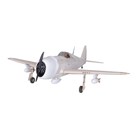
Code : SEA 207K
ASSEMBLY MANUAL
Specifications:
Wingspan--------------- 63.0 in (160.0 cm).
Wing area--------------- 728.5 sq.ins (47.0 sq.dm).
Weight------------------- 9.3-9.9 lbs (4.2-4.5 kg).
Length------------------- 51.8 in (131.5 cm).
Engine ------------------ 0.61 - 0.91 cu.in----2 stroke.
---------------------------- 0.91- 1.00 cu.in----4 stroke.
---------------------------- 15cc gasoline engine .
Radio--------------------- 6 channels with 9 servos.
1
Advertisement
Table of Contents

Related Manuals for Seagull Models P-47D Thunderbolt 60


Summary of Contents for Seagull Models P-47D Thunderbolt 60
- Page 1 Code : SEA 207K ASSEMBLY MANUAL Specifications: Wingspan--------------- 63.0 in (160.0 cm). Wing area--------------- 728.5 sq.ins (47.0 sq.dm). Weight------------------- 9.3-9.9 lbs (4.2-4.5 kg). Length------------------- 51.8 in (131.5 cm). Engine ------------------ 0.61 - 0.91 cu.in----2 stroke. ---------------------------- 0.91- 1.00 cu.in----4 stroke. ---------------------------- 15cc gasoline engine .
- Page 2 Instruction Manual. P-47D Thunderbolt 60 Kit INTRODUCTION - Congratulations and thank you for purchasing the P47 Thunderbolt. We are pleased to bring you this scale P47. with this kit you can achieve whatever level of detail you like. Just by following the instruction and fin- ishing the plane in scale-looking trim scheme, beginning scale modelers will end up with a model that very much represents and full-size P47.
- Page 4 Instruction Manual. P-47D Thunderbolt 60 Kit...
- Page 6 Instruction Manual. P-47D Thunderbolt 60 Kit...
- Page 8 Instruction Manual. P-47D Thunderbolt 60 Kit...
-
Page 9: Build The Fuselage
BUILD THE FUSELAGE - Fill White Glue on the surface of the 1st firewall - Firewall ( 3pcs). - Put the 2 firewall F0 on 1 firewall F0 to paste them together. - Apply White Glue to the surface of the firewall F0’... - Page 10 Instruction Manual. P-47D Thunderbolt 60 Kit - Arrange the left fuselage side S1, S1’ and the right - Apply White Glue to the surface of left fuselage fuselage side S2, S2’ as photo for difference be- side S1 at area need to paste S1’ .
- Page 11 - Apply CA Glue to keep fixed former F1 and the right fuselage side S2, S2’ . - Install firewall block with the right fuselage side S2,S2’ by Epoxy glue. Continue to install former F13 as the in- struction photos below. - Put former F1 on the right fuselage side S2,S2’...
- Page 12 Instruction Manual. P-47D Thunderbolt 60 Kit 21 .
- Page 14 Instruction Manual. P-47D Thunderbolt 60 Kit...
- Page 16 Instruction Manual. P-47D Thunderbolt 60 Kit - Use White Glue to paste former F14’ ( 2pcs) on former F14. - Apply CA Glue around block include 3 layers for- mer F14, F14’ .
- Page 17 - Attach M3 blind nut ( 4pcs) to block of former - Apply CA Glue to keep fixed block former F14, F14, F14’ . F14’ with two side of fuselage. - Apply CA Glue around M3 blind nut ( 4pcs). - Continue to install for the end former.
- Page 18 Instruction Manual. P-47D Thunderbolt 60 Kit - Install F26 and apply CA Glue to keep fixed. - Install F16 and apply CA Glue to keep fixed. - Install F27 and apply CA Glue to keep fixed. - Install F2’ to F2 by White Glue.
- Page 19 - Install F17 ( 3pcs) to fuselage and apply CA Glue to keep fixed. - Paste F19’ on F19 by CA Glue. - Install F18 ( 2pcs) to fuselage and apply CA Glue to keep fixed. - Attach M4 blind nut to block of former F19, F19’ and apply CA Glue around M4 blind nut.
- Page 20 Instruction Manual. P-47D Thunderbolt 60 Kit - Install F20 ( 2pcs) to fuselage and apply CA Glue to keep fixed. - Install H17 to fuselage and apply CA Glue to keep fixed. - Install F32 to fuselage and apply CA Glue to keep...
- Page 21 - Install F23 ( 2pcs) to fuselage and apply CA Glue to keep fixed. - Use sandpaper bar to sanding F21, so that mak- ing a flat with fuselage side. - Install F21 ( 2pcs) to fuselage and apply CA Glue to keep fixed.
- Page 22 Instruction Manual. P-47D Thunderbolt 60 Kit - Install F21’ ( 2pcs) to fuselage at right side and left side and apply CA Glue to keep fixed. - Install F25 to fuselage at right side and left side, then apply CA Glue to keep fixed.
- Page 23 100. - Getting prepare the plastic tube ( 4pcs) with Ø = 5mm ; 36cm length (photo 103). 104. 101. - The plastic tube to go through all formers which have path of Fin and path of Elevator hole on each former and fill White Glue to keep fixed.
- Page 24 Instruction Manual. P-47D Thunderbolt 60 Kit COVER TO THE RIBS OF FUSELAGE If the balsa sheet quite hard, we should use the wet towel so that making soft the balsa sheet. - Use cutter knife cut off redundantcy of SH3.
- Page 25 - Cover the sheet SH14 on ribs of fuselage at the - Cover the sheet SH2 on ribs of fuselage at the left right side. side. - Cover the sheet SH13 on ribs of fuselage at the left side.
- Page 26 Instruction Manual. P-47D Thunderbolt 60 Kit - Cover the sheet SH11 on ribs of fuselage at the both of side. - Cover the sheet SH12 on ribs of fuselage at the both of side. - Cover the sheet SH7 on ribs of fuselage at the both of side.
- Page 27 - Cover the sheet SH6 on ribs of fuselage at the both of side apply CA Glue to keep fixed. - Cover the sheet SH5 on ribs of fuselage at the both of side. - Cover the sheet SH8 on ribs of fuselage at the both of side and apply CA Glue to keep fixed the sheet SH8.
- Page 28 Instruction Manual. P-47D Thunderbolt 60 Kit - Install F30 and F31 (8mm balsa wood ) to fuse- Should use the wing as instruction photo so lage and apply CA Glue to keep fixed. that installing FW exactly as photo. - Use cutter knife to cut off redundantcy wood of - Apply CA Glue to keep fixed FW.
- Page 29 - Install 16mm block F22 to the fuselage by White - Roll sandpaper around the paper tube so that Glue. making a sandpaper tube. - Sanding wood block F22 so that shaping the wing - Apply CA Glue to keep fixed 16mm block F22 fillet.
- Page 30 Instruction Manual. P-47D Thunderbolt 60 Kit - Use countersink with Ø = 3mm, to drill the hole for bomb at the bottom of fuselage as photo. - Install F22 to fuselage and apply CA Glue to keep fixed. - The fuselage was finished.
- Page 31 - Paste F15’ on the end of fuselage at F15 by CA - Use sandpaper bar to sanding at block of tab as Glue. photo. - Getting prepare set of cowling mount include set of tap ( 4set) and F1’ . - Install F1’...
-
Page 32: Installing The Fuselage Servos
Instruction Manual. P-47D Thunderbolt 60 Kit - Apply white Glue to keep fixed paper tube. - Apply white Glue to the surface of the triangle block as photo. INSTALLING THE FUSELAGE SERVOS Because the size of servos differ, you may need to adjust the size of the precut opening in the mount. -
Page 33: Installing The Stopper Assembly
THROTTLE SERVO ARM Vent tube. Fuel pick up tube. INSTALLATION - Install adjustable servo connector in the servo arm as same as picture below: Fuel fill tube. - Carefully bend the second nylon tube up at a 45º angle. This tube is the vent tube. - Test fit the stopper assembly into the tank. - Page 34 Instruction Manual. P-47D Thunderbolt 60 Kit - Slide the fuel tank into the fuselage. Guide the lines from the tank through the hole in the fiewall. - Use plywood template to hold in place the fuel tank with C/A glue to secure the fuel tank inside the fuselage.
- Page 35 - On the fie wall has the location for the throttle - Move the throttle stick to the closed position and move the carburetor to closed. Use a 2.5mm hex pusshrod tube (pre-drill). wrench to tighten the screw that secures the throt- - Slide the pushrod tube in the fiewall and guide it tle pushrod wire.
- Page 36 Instruction Manual. P-47D Thunderbolt 60 Kit - Slide the fberglass cowl over the engine and line up the back edge of the cowl with the marks you made on the fuselage then trim and cut as shown. - Because of the size of the cowl, it may be nec es- sary to use a needle valve extension for the high speed needle valve.
- Page 37 - Install the mufer and mufer extension onto the - Paste prepare aluminium square tool on canopy engine and make the cutout in the cowl for mufer at the bottom by sticky tape. clearance. Connect the fuel and pressure lines to the carburetor, mufer and fuel fller valve.
- Page 38 Instruction Manual. P-47D Thunderbolt 60 Kit - Attach M4 blind nut to the latch and then fill CA glue around. - Getting prepare 2 set of latch at behind include H10’ ( 4pcs). - Attach the latch to canopy at behind by CA glue.
- Page 39 - Cover the rest of the clear area with making tape - Install canopy to fuselage and use the sandpaper so that mask off protect it from over spray (photo bar so that sanding for canopy and fuselage until 15.16). look seamless.
- Page 40 Instruction Manual. P-47D Thunderbolt 60 Kit - Position the canopy onto the fuselage. Trace INSTALLATION PILOT AND CANOPY around the canopy and onto the fuselage using a felt-tipped pen. - Locate items necessary to install pilot, seats. - A scale pilot is included with this ARF. The Pilot BUILD SET OF THE WING included fiting well to the coc pit.
- Page 41 - Getting prepare the perpendicular frame include 2 pcs paste on together. - Paste W28 on W29 by White Glue. - The Aluminium Square Fixed Tool be separated 2 parts. - Apply thin CA Glue around block include 2 lay- ers of trailing edge.
- Page 42 Instruction Manual. P-47D Thunderbolt 60 Kit - Apply CA Glue to keep fixed the airfoil. - Use the clamp to hold on perpendicular alumini- um frame and the ribs of wing together. - Install leading edge to the ribs of wing.
- Page 43 Please kindly see the view of wing in the drawing sheet. - Install F15 to wing and apply CA Glue to keep fixed as photo. - Install W13 and W32 to wing and apply CA Glue to keep fixed as photo. - Use sandpaper bar to sanding at the end airfoil of wing as photo.
- Page 44 Instruction Manual. P-47D Thunderbolt 60 Kit - Install W15’(6mm balsa wood) to wing and apply CA Glue to keep fixed as photo. - Install W5 to wing by White Glue to keep fixed as photo. 27 . - Paste two pieces retract gear mount W21 togeth- er by White Glue.
- Page 45 - Apply thin CA Glue to around block include 2 - Install retract gear mount W21 to wing by White layers W21. Glue and then fill CA Glue to keep fixed. - Paste W22 on W21 by White Glue as photo.
- Page 46 Instruction Manual. P-47D Thunderbolt 60 Kit - Paste W23 on block include W21, W22 by White - Getting prepare set of nut for nylon bolt include Glue and then fill CA Glue to mount to keep fixed. W34 (2pcs) and a nylon nut as photo.
- Page 47 - Apply CA glue to keep fixed W18. - Install servo mount WS3, WS4, WS5 to wing by CA glue. - Getting prepare W18 and M3 blind nut and at- taching M3 blind nut to W18 by White glue. - Apply White glue on trailing edge as photo. - Install W18 with blind nut available to W2 by White glue.
- Page 48 Instruction Manual. P-47D Thunderbolt 60 Kit - The side of wing with servo mount flip up as pho- - Sheeting was finished. -Use sandpaper bar to sanding 6mm balsa block - Apply balsa frame W25 to balsa sheet W39 at make shape for balsa block as photo.
- Page 49 - Cover balsa sheet W38 for 2nd side of wing by White glue as photo. - Measure and split to two fragment of 6mm balsa block for leading edge. - Hold the sheet down with weights while the glue dries. - Attach two fragment of 6mm balsa block to lead- ing edge by CA glue.
- Page 50 Instruction Manual. P-47D Thunderbolt 60 Kit - Install W33 by CA glue. - Paste W16 on W4 by White Glue. - Cover balsa sheet W35 and W36 at servo area (photo 62 to 66).
- Page 51 - The paper tube through W1, W2, W3, W4 and then apply White glue at intersection of the wing rib and the tube as photo. - Apply CA glue to keep fixed W40. - Cut off the paper tube at wing root as photo. - Use sandpaper bar to sanding at 6mm balsa block W15’...
- Page 52 Instruction Manual. P-47D Thunderbolt 60 Kit - The aluminium tube through the ribs and then fill CA glue to keep fixed. - Use sandpaper bar to sanding at trailing edge . - Paste W1 on W1’ by CA glue to keep fixed.
- Page 53 BUILD THE FLAP AND AILERON - Sanding leading edge was finished. - Getting prepare set of flap as photo. - Use sandpaper to sanding around wing. - Install the ribs of flap to balsa sheet WA15 and leading edge of flap WA14 by CA glue. - Building the wing was finished.
- Page 54 Instruction Manual. P-47D Thunderbolt 60 Kit - Apply CA glue to keep fixed as photo. - Apply CA glue at leading edge WA19 with balsa sheet WA15 to keep fixed as photo. - Use sandpaper bar to sanding at root rib of flap.
- Page 55 - Install the ribs of aileron to balsa sheet WA17 and leading edge of aileron WA13 by CA glue. - Use sandpaper bar to sanding make the angle of flap. - Apply white glue to the ribs of aileron as photo. - The flap was finished.
- Page 56 Instruction Manual. P-47D Thunderbolt 60 Kit - Use the pen make the mark of hinge on flap fol- - Paste balsa block WA20 on leading edge of aile- low wing. ron by white glue. - Use the pen make the mark of hinge on aileron - Apply CA glue at leading edge WA20 with balsa follow wing.
- Page 57 - Deflect the flap and completely saturate each HINGING THE FLAP hinge with thin C/A glue. The ailerons front surface should lightly contact the wing during this proce- dure. Ideally, when the hinges are glued in place, Note : The control surfaces, including the ailerons, a 1/64”...
-
Page 58: Hinging The Aileron
Instruction Manual. P-47D Thunderbolt 60 Kit Note : Work the aileron up and down several times to “work in” the hinges and check - Slide the wing panel on the aileron until there is for proper movement. only a slight gap. The hinge is now centered on the wing panel and aileron. - Page 59 - Using C/A remover/debonder and a paper towel, remove any excess C/A glue that may have accu- mulated on the wing or in the aileron hinge area. - Repeat this process with the other wing panel, se- curely hinging the aileron in place. - After both ailerons are securely hinged, firmly grasp the wing panel and aileron to make sure the hinges are securely glued and cannot be pulled out.
-
Page 60: Installing The Aileron Servos
Instruction Manual. P-47D Thunderbolt 60 Kit INSTALLING THE AILERON SERVOS - Use drill bit in a pin vise to drill the mouting holes in the blocks. - A string has been provided in the wing to pull the Minimum servo spec. -
Page 61: Aileron Pushrod Installation
INSTALLING THE LIGHT COVER AILERON PUSHROD INSTALLATION - Please see below pictures. INSTALLING THE FLAP PUSHROD - Repeat the procedure for the aileron pushrod. -
Page 62: Landing Gear
Instruction Manual. P-47D Thunderbolt 60 Kit INSTALLING RETRACTABLE LANDING GEAR - Locate the items necessary to install the retracta- ble landing gear as shown. RETRACTABLE LANDING GEAR SERVO - PUSHROD INSTALLATION - Locate items necessary to install landing gear pushrod. - Page 63 BUILD THE HORIZONTAL STAB...
- Page 64 Instruction Manual. P-47D Thunderbolt 60 Kit - Install the ribs of stabilizer as photo. - Hold the sheet down with weights while the glue dries and apply CA/glue to the sheet at trailing edge. - Cover balsa sheet ST14 for 1st side by white glue and then apply CA glue to keep fixed.
-
Page 65: Build The Elevator
- Use cutter to sharpen the ST12 for flatting surface - Install the ribs of elevator to balsa sheet ST15 and of stabilizer. leading edge of elevator ST13 by white glue. - Apply white glue to the ribs of elevator and cover - Use sandpaper bar for sanding the surface of sta- the balsa sheet ST15’... - Page 66 Instruction Manual. P-47D Thunderbolt 60 Kit - Use cutter knife to sharpen the ST16 for flatting - Use the pen make the mark of hinge on elevator surface of elevator. follow stabilizer. - Set of Stab and elevator was buildded .
-
Page 67: Hinging The Elevators
- Using a ruler and a pen, locate the centerline of HINGING THE ELEVATORS the horizontal stabilizer, at the trailing edge, and place a mark. Use a triangle and extend this mark, from back to front, across the top of the stabilizer. - Glue the elevator hinges in place using the same Also extend this mark down the back of the trail- techniques used to hinge the ailerons. -
Page 68: Build The Rudder
Instruction Manual. P-47D Thunderbolt 60 Kit - With the stabilizer held firmly in place, use a pen - When you are sure that everything is aligned and draw lines onto the stabilizer where it and the correctly, mix up a generous amount of 30 Minute fuselage sides meet. - Page 69 - Apply white glue to the ribs of rudder. - Cover balsa sheet T17 at botton of rudder as pho- - Cover 2nd balsa sheet T19 to the ribs of rudder. - Cover balsa sheet T18 for two side as photo. - Apply CA glue at the tabs show on the sheet to keep fixed.
-
Page 70: Build The Fin
Instruction Manual. P-47D Thunderbolt 60 Kit - Use sandpaper bar for sanding the surface of rud- - Attach 8mm balsa block for two side by CA glue der. as photo. - Attach 8mm balsa block T5’ by CA glue as photo. - Page 71 - Cover balsa sheet T20 on the ribs of fin. - Install the ribs of fin to balsa sheet T22 and lead- ing edge of fin T15 and then attach 6mm balsa - Apply CA glue at the tabs show on the sheet to block T13 by CA glue as photo.
- Page 72 Instruction Manual. P-47D Thunderbolt 60 Kit - Paste 2 pieces 8mm balsa block T21 together by CA glue. - Apply white glue to leading edge so that triangle balsa block. - Apply CA glue to keep fixed triangle balsa block.
- Page 73 - Use the pen make the mark of hinge on the fin - Use cutter knife to sharpen the T21 for flatting follow rudder. surface of fin. - Use sandpaper bar for sanding around the fin. - Use the cutter knife cut off a slot for hinge. - Building the fin was finished.
- Page 74 Instruction Manual. P-47D Thunderbolt 60 Kit - Use sandpaper to sanding around set of rudder - Put the stabilizer and continue to sanding until and fin. fitting, there no slit at here. At the same time, the stabilizer and the wing tube have to parallel togeth-...
-
Page 75: Installing Vertical Stabilizer
- Set up the kit was finished. INSTALLING VERTICAL STABILIZER HINGING THE RUDDER - Glue the rudder hinges in place using the same techniques used to hinge the ailerons. - Using a modeling knife, remove the covering from over the precut hinge slot cut into the lower rear portion of the fuselage. - Page 76 Instruction Manual. P-47D Thunderbolt 60 Kit - While holding the vertical stabilizer fimly in place, use a pen and draw a line on eachside of the vertical stabilizer where it meets the top of the fu- selage. - When you are sure that everything is aligned cor- rectly, mix up a generous amount of Flash 30 Min- ute Epoxy.
-
Page 77: Rudder Pushrod Installation
- Thead one clevis and M2 lock nut on to each el- evator control rod. Thead the horns on until they RUDDER PUSHROD INSTALLATION are flsh with the ends of the control rods. - Locate items necessaryto install rudder pushrod. - Elevator and rudder pushrods assembly as pic- tures below. -
Page 78: Mounting The Tail Wheel
Instruction Manual. P-47D Thunderbolt 60 Kit MOUNTING THE TAIL WHEEL - Locate items necessary to intall tail wheel. - Page 79 - Insert fuel tank onto the wings.
- Page 80 Instruction Manual. P-47D Thunderbolt 60 Kit - Getting prepare set of servo mount include WS1, WS2 (2 pcs), WS6 (2 pcs) as photo. - The first, build servo mount by CA glue and then BUILD THE SERVO MOUNT apply white glue to keep fixed.
-
Page 81: Build The Motor Mount
BUILD THE MOTOR MOUNT - Paste 3 pieces MO1 together by white glue and then apply CA glue around block include 3 layer to keep fixed. - Getting prepare set of motor mount include MO1 ( 3pcs), MO2 ( 1pcs), MO3 ( 2pcs), MO4 ( 2pcs), MO5 (1pcs). - Page 82 Instruction Manual. P-47D Thunderbolt 60 Kit - Attach MO1 block to MO4 by CA glue(photo - Paste MO3 block on MO2 by white glue and ap- 9,10). ply CA glue around block include 3 layer to keep fixed. And then attach to MO4 by CA glue.
- Page 83 - Locate the items neccessary to install the - Continue to attache M05 at the botton of motor electric power conversion included with your mount by CA glue (photo 12,13). model. - Getting prepase two triange block lenght = 65mm. - Recommend the items necessary to install the electric power conversion parts included with your model.
- Page 84 Instruction Manual. P-47D Thunderbolt 60 Kit - Attach the motor to the front of the electric motor box using four 4mm blind nut, four M3x15mm hex head bolts to secure the motor. Please see picture shown. - Attach the motor mount to the front of the...
-
Page 85: Control Throws
- Lif the model. If the tail drops when you lift BALANCING the model is “tail heavy” and you must add weight* to the nose. If the nose drops, it is - It is critical that your airplane be “nose heavy” and you must add weight* to the tail to balance. - Page 86 Instruction Manual. P-47D Thunderbolt 60 Kit...
- Page 87 If you have any queries, or are interested in our products, please feel free to contact us Factory : 12/101A - Hamlet 4 - Le Van Khuong Street - Dong Thanh Ward - Hoc Mon District - Ho Chi Minh City - Viet Nam. Office : 62/8 Ngo Tat To Street - Ward 19 - Binh Thanh District - Ho Chi Minh City - Viet Nam Phone : 848 - 86622289 or 848- 36018777...
Need help?
Do you have a question about the P-47D Thunderbolt 60 and is the answer not in the manual?
Questions and answers