Table of Contents
Advertisement
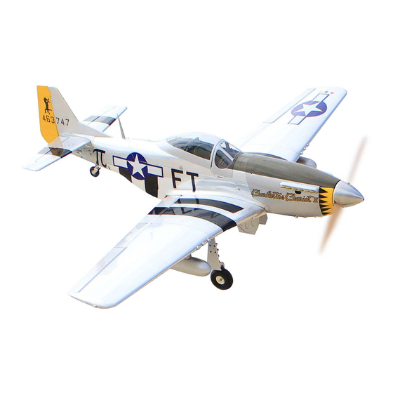
Code : SEA391
ASSEMBLY MANUAL
Speciications:
Wingspan--------------- 71 in------------------------ 180 cm.
Wing area--------------- 893.1 sq.ins--------------- 57.6 sq.dm.
Weight------------------- 17.2 - 17.6 lbs------------- 7.8 - 8.0 kg.
Length------------------- 57 in------------------------ 144.8 cm.
Engine------------------- 35cc.
Motor-------------------- 160/ 2700watt/ ESC 100A-120A/ Lipo 6s -12s
electric propeller 18x8 - 20x10.
Radio--------------------- 9 channels with 10 servos.
1
Advertisement
Table of Contents

Related Manuals for Seagull Models North American P-51D Charlotte's Chariot II 71 ARF 35cc


Summary of Contents for Seagull Models North American P-51D Charlotte's Chariot II 71 ARF 35cc
- Page 1 Code : SEA391 ASSEMBLY MANUAL Speciications: Wingspan--------------- 71 in------------------------ 180 cm. Wing area--------------- 893.1 sq.ins--------------- 57.6 sq.dm. Weight------------------- 17.2 - 17.6 lbs------------- 7.8 - 8.0 kg. Length------------------- 57 in------------------------ 144.8 cm. Engine------------------- 35cc. Motor-------------------- 160/ 2700watt/ ESC 100A-120A/ Lipo 6s -12s electric propeller 18x8 - 20x10.
-
Page 2: Kit Contents
Instruction Manual. North American P-51D “Charlotte’s Chariot II’ 71” ARF 35cc INTRODUCTION hank you for choosing the North American P-51D “Charlotte’s Chariot II’ 71” ARF 35cc ARTF manufactured by SG MODELS. he North American P-51D “Charlotte’s Chariot II’ 71” ARF 35cc was designed with the intermediate/advanced sport lyer in mind. It is a semi scale airplane which is easy to ly and quick to assemble. -
Page 3: Additional Items Required
WING TIP BULBS KIT CONTENTS SEA391 North American P-51D Please see below pictures. “Charlotte’s Chariot II’ 71” ARF 35cc 1. Fuselage 2. Wing set (3 pcs) 3. Tail set (2 pcs) 4. Canopy 5. Cowling 6. Wing tube 7. Fuel tank 8. - Page 4 Instruction Manual. North American P-51D “Charlotte’s Chariot II’ 71” ARF 35cc C/A glue...
-
Page 5: Install The Ailerons
INSTALL THE AILERONS Please see pictures below.. Insert all four hinges in the ailerons at this time. Make sure hinges move up and down in right direction and not side to side ! Epoxy Remove the ailerons from the wing and remove the hinges. - Page 6 Instruction Manual. North American P-51D “Charlotte’s Chariot II’ 71” ARF 35cc Be sure to test the aileron hinges once you insert them. Ensure that the hinge pockets line up, and that the hinges move freely before the epoxy dries. Epoxy Check the it of the aileron to the wing.
-
Page 7: Installing The Aileron Servos
Because the size of servos difer, you may need to adjust the size of the precut opening in the mount. he notch in the sides of the mount allow the servo lead to pass through. Place the servo between the mounting blocks and space it from the hatch. - Page 8 Instruction Manual. North American P-51D “Charlotte’s Chariot II’ 71” ARF 35cc Use dental loss or heat shrink tubing to secure the connection between the servo and extension wire so they cannot become unplugged accidentally. Secure the servo to the aileron hatch using a proper driver and the screws provided with the servo.
-
Page 9: Aileron Pushrod Installation
INSTALLING THE FLAP PUSHROD 70mm AILERON PUSHROD INSTALLATION 40mm... -
Page 10: Wing Assembly
Instruction Manual. North American P-51D “Charlotte’s Chariot II’ 71” ARF 35cc WING ASSEMBLY Please study images below. 4x12mm INSTALLING RETRACTABLE LANDING GEAR PLocate items necessary to install Sprin Landing Gear. 4x12mm You use this fork set JP ER-120-90degree. - Page 11 When injecting C/A glue, bring the forks inwards so they don’t move. C/A glue 15mm 15mm 25mm 10mm 25mm 10mm 100mm...
- Page 12 Instruction Manual. North American P-51D “Charlotte’s Chariot II’ 71” ARF 35cc M3x4mm M3x20mm...
- Page 13 M3x10mm M3x4mm Collar M3x4mm...
- Page 14 Instruction Manual. North American P-51D “Charlotte’s Chariot II’ 71” ARF 35cc Epoxy Epoxy...
- Page 15 he servo motor should be at least 25mm in size. 25mm Mininum servo. Torque : 8.7 oz-in (6.3 kg-cm) @ 6V; 118 oz-in (8.5 kg-cm) @ 8.4V Encourage the use of servos such as Spektrum.a5060. Note: he speed of this servo you to be in the slowest mode then you gradually in- crease to suit the speed ranked.
- Page 16 Instruction Manual. North American P-51D “Charlotte’s Chariot II’ 71” ARF 35cc Epoxy 85mm...
- Page 17 DROP TANK/BOMB INSTALLATION Please study images below. Install drop tank/bomb releases as shown. 2.5x6mm...
- Page 18 Instruction Manual. North American P-51D “Charlotte’s Chariot II’ 71” ARF 35cc 2.5x6mm M3x45mm...
- Page 19 2.5x6mm If you do not wish to make the drop tanks/bomb removable you may glue them in place. Please study images below. ***We do recommend making them re- movable for maintenance/service.
- Page 20 Instruction Manual. North American P-51D “Charlotte’s Chariot II’ 71” ARF 35cc INSTALLING THE FUSELAGE SERVOS Because the size of servos difer, you may need to adjust the size of the precut opening in the mount. he notch in the sides of the mount allow the servo lead to M2x12mm pass through.
-
Page 21: Installation
THROTTLE SERVO ARM INSTALLATION Install adjustable servo connector on the servo arm and set aside for now. Switch Rudder servo arm INSTALLING THE ENGINE SWITCH Elevator servo arm Trim and cut Install the rudder and elevator servo arms as shown above. INSTALLING THE RECEIVER SWITCH Install the switch into the precut hole in the side of fuselage, or you may hide... -
Page 22: Fuel Tank Installation
Instruction Manual. North American P-51D “Charlotte’s Chariot II’ 71” ARF 35cc You should mark which tube is the vent and which is the fuel pickup when you attach fuel tubing to the tubes in the stopper. Once the tank is installed inside the fuselage, it may be diicult to determine which is which. -
Page 23: Mounting The Engine
Blow through one of the lines to ensure the fuel lines have not become kinked inside the fuel tank compartment. Air should low through easily. MOUNTING THE ENGINE Please study the images be low. 5.2mm Locate the engine mounting in position on the irewall. -
Page 24: Throttle Servo Installation
Instruction Manual. North American P-51D “Charlotte’s Chariot II’ 71” ARF 35cc Attach throttle pushrod to the carbure- tor throttle arm with the ball link. M5x110mm 174mm 4x5mm THROTTLE SERVO INSTALLATION Move the throttle stick to the closed po- sition and move the carburetor to closed. Use a 2.5mm hex wrench to tighten the screw that secures the throttle pushrod wire. -
Page 25: Ignition Installation
Secure ignition wire with nylon ties as necessary. IGNITION INSTALLATION I hread nylon tie through mounting holes. Connect ignition module to pickup line of engine. Secure with Safety Clip, safety wire, tape or other method. Ensure the plugs will not come apart from vibration or light tension. - Page 26 Instruction Manual. North American P-51D “Charlotte’s Chariot II’ 71” ARF 35cc COWLING Please study images below. For cooling engine and battery. Please cut to remove plastic part of cowl go to triangle decoration shape available. Note: Skip a next triangle shape. Go on cut to remove a triangle shape.
- Page 27 Tape the cowl to the fuselage using Install the muler onto the engine and low-tack tape. make the cutout in the cowl for muler clearance. Connect the fuel and pressure lines to the carburetor, muler and fuel iler valve. Secure the cowl to fuselage using the M3x10mm socket head screws.
- Page 28 Instruction Manual. North American P-51D “Charlotte’s Chariot II’ 71” ARF 35cc Recommend the items necessary to in- stall the electric power conversion parts included with your model. - Motor: 160/ 2700watt - Propeller: 18x8 - 20x10 - ESC: 100-120A - 6S- 12S Lipo Attach the electric motor box to the irewall centered with the cross lines ELECTRIC POWER CONVERSION...
- Page 29 5.5mm M5x30mm and washers hen, use 5.5mm drill bit to enlarge the Attach the motor to the front of the holes on the electric motor box. electric motor box using four 4mm blind nut, four M5x30mm hex head bolts to se- cure the motor.
- Page 30 Instruction Manual. North American P-51D “Charlotte’s Chariot II’ 71” ARF 35cc M4x20mm 174mm Battery Attach the speed control to the side of the motor box using two-sided tape and tie wraps. Connect the appropriate leads from the speed control to the motor. Make sure the leads will not interfere with the operation of the motor.
-
Page 31: Install The Chimney
Epoxy 4x25mm INSTALL THE CHIMNEY Please study images below. - Page 32 Instruction Manual. North American P-51D “Charlotte’s Chariot II’ 71” ARF 35cc Epoxy INSTALL NAIL HINGE ELEVATOR Test it the hinges into the elevator, and then the hinges into the tail. Ensure that the hinge pockets line up, and that the hinges move freely.
- Page 33 Epoxy INSTALL ELEVATOR CONTROL HORN Install the elevator control horn using the same method as same as the elevator control horns.
-
Page 34: Hinging The Rudder
Instruction Manual. North American P-51D “Charlotte’s Chariot II’ 71” ARF 35cc Epoxy HINGING THE RUDDER Glue the top three rudder hinges in place using the same techniques used to hinge the elevator. he lower hinge will be glued when the in/rudder assembly is attached to the fu- selage. -
Page 35: Installing The Horizontal Stabilizer
INSTALL RUDDER CONTROL HORN Repeat steps to install the rudder control horn as same as steps done for elevator. Epoxy Fiberglass control horn Epoxy Rudder iberglass control horn INSTALLING THE HORIZONTAL STABILIZER Epoxy Required Parts • Fuselage assembly • Tail Set(Rudder and Elevator) Required Tools and Adhesives •... - Page 36 Instruction Manual. North American P-51D “Charlotte’s Chariot II’ 71” ARF 35cc Using a ruler and a pen, locate the cen- terline of the horizontal stabilizer, at the trailing edge, and place a mark. Use a tri- angle and extend this mark, from back to front, across the top of the stabilizer.
- Page 37 Fill Epoxy Fill Epoxy When cutting through the covering INSTALLING VERITICAL FIN to remove it, cut with only enough pressure to only cut through the covering itself. Cut- ting into the balsa structure may weaken Required Parts • Fuselage assembly •...
- Page 38 Instruction Manual. North American P-51D “Charlotte’s Chariot II’ 71” ARF 35cc When you are sure that everything is aligned correctly, mix up a generous Fill Epoxy amount of Flash 30 Minute Epoxy. Ap- ply a thin layer to the mounting slot and to bottom of the vertical stabilizer mounting area.
-
Page 39: Rudder Cable Installation
Ball Link Elevator pushrod Ball Link RUDDER CABLE INSTALLATION Study images below to install pull-pull cable set. - Page 40 Instruction Manual. North American P-51D “Charlotte’s Chariot II’ 71” ARF 35cc...
- Page 41 MOUNTING THE TAIL GEAR 3x15mm Gather tail gear components as shown below for installation.
-
Page 42: Cockpit Installation
Instruction Manual. North American P-51D “Charlotte’s Chariot II’ 71” ARF 35cc COCKPIT INSTALLATION Locate all cockpit components as shown below. - Page 43 C/A glue Use C/A glue to inject the underside of the control panel. C/A glue C/A glue...
- Page 44 Instruction Manual. North American P-51D “Charlotte’s Chariot II’ 71” ARF 35cc C/A glue 50mm C/A glue...
- Page 45 Note: Magnets with diferent poles will attract each other. Epoxy C/A glue Carbon 3x10mm...
- Page 46 Instruction Manual. North American P-51D “Charlotte’s Chariot II’ 71” ARF 35cc C/A glue C/A glue...
- Page 48 Instruction Manual. North American P-51D “Charlotte’s Chariot II’ 71” ARF 35cc Use double-sided tape to temporarily stick it, then remove it and apply glue. C/A glue...
- Page 49 C/A glue...
- Page 50 Instruction Manual. North American P-51D “Charlotte’s Chariot II’ 71” ARF 35cc Epoxy Epoxy...
- Page 51 Epoxy...
- Page 52 Instruction Manual. North American P-51D “Charlotte’s Chariot II’ 71” ARF 35cc Epoxy Epoxy Epoxy...
- Page 53 Epoxy Epoxy...
- Page 54 Instruction Manual. North American P-51D “Charlotte’s Chariot II’ 71” ARF 35cc ATTACH WING TO FUSELAGE Locate the (2) 6x50mm bolts and washers. INSTALLING BATTERY - RECEIVER Plug the servo leads and the switch lead into the receiver. Plug the battery pack lead into the switch also.
-
Page 55: Installing Antennas
INSTALLING ANTENNAS Antennas feature banana plugs for easy installation and removal. M6x50mm... - Page 56 Instruction Manual. North American P-51D “Charlotte’s Chariot II’ 71” ARF 35cc INSTALL THE WING GUNS Locate the 4 Gun as seen in images below. Epoxy...
- Page 57 With the model inverted, place your APPLYNG DECALS ingers on the masking tape and carefully lit the plane. his is the point at which Please use scissors and/or a hobby your model should balance for your irst knife to cut the decals from the sheet. lights.
-
Page 58: Control Throws
Instruction Manual. North American P-51D “Charlotte’s Chariot II’ 71” ARF 35cc CONTROL THROWS Rudder: Ailerons: High Rate : High Rate : Up : 20 mm Right : 25 mm Down : 20 mm Let : 25 mm Low Rate : Low Rate : Up : 15 mm Right : 20 mm... -
Page 59: Flight Preparation
FLIGHT PREPARATION PREFLIGHT CHECK 1) Completely charge your trans- Check the operation and direction mitter and receiver batteries before of the elevator, rudder, ailerons and your irst day of lying. throttle. 2) Check every bolt and every glue A) Plug in your radio system per the joint in the manufacturer’s instructions and turn North American P-51D... - Page 60 Instruction Manual. North American P-51D “Charlotte’s Chariot II’ 71” ARF 35cc If you have any queries, or are interested in our products, please feel free to contact us Factory : 12/101A - Hamlet 4 - Le Van Khuong Street - Dong hanh Ward - Hoc Mon District - Ho Chi Minh City - Viet Nam.
Need help?
Do you have a question about the North American P-51D Charlotte's Chariot II 71 ARF 35cc and is the answer not in the manual?
Questions and answers