Seagull Models PC-9 Instruction Manual
Hide thumbs
Also See for PC-9:
- Assembly manual (25 pages) ,
- Assembly manual (20 pages) ,
- Assembly manual (26 pages)
Table of Contents
Advertisement
Quick Links
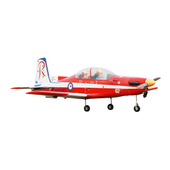
PC - 9
"Graphics and Specfications may change without notice".
Specifications
Wingspan--------------------------------- 71 in --------------------- 180.3cm.
Wing area-------------------------------- 789 sq.in ------------- 50.9 sq.dm.
Weight------------------------------------ 10.1-11.9lbs -----------4.6-5.4 kg.
Length------------------------------------- 66.1 in ------------------- 167.9cm.
Recommended engine size---------- 1.20 cu.in ---------------- 2-stroke.
Radio System required 6 channel with 6 servos.
Flying skill level Intermediate/advanced.
Kit features.
•
Ready-made—minimal assembly & finishing required.
•
Ready-covered covering.
•
Photo-illustrated step-by-step Assembly Manual.
Made in Vietnam.
ASSEMBLY MANUAL
1.20-1.50---------------- 4 - stroke.
MS: SEA 94
.
Advertisement
Table of Contents

Related Manuals for Seagull Models PC-9


Summary of Contents for Seagull Models PC-9
- Page 1 PC - 9 MS: SEA 94 ASSEMBLY MANUAL “Graphics and Specfications may change without notice”. Specifications Wingspan--------------------------------- 71 in --------------------- 180.3cm. Wing area-------------------------------- 789 sq.in ------------- 50.9 sq.dm. Weight------------------------------------ 10.1-11.9lbs -----------4.6-5.4 kg. Length------------------------------------- 66.1 in ------------------- 167.9cm. Recommended engine size---------- 1.20 cu.in ---------------- 2-stroke. 1.20-1.50---------------- 4 - stroke.
- Page 2 . Flying the PC-9 is simply a joy. This instruction manual is designed to help you build a great flying aeroplane. Please read this manual thoroughly before starting assembly of your PC-9 . Use the parts listing below to identify all parts.
-
Page 3: Hinging The Ailerons
Please trial fit all parts. Make sure you have the correct parts and that they fit and are aligned properly before gluing! Hinge This will ensure proper assembly as PC-9 is made from natural materials and minor adjustments may have to be made. The paint and... -
Page 4: Hinging The Elevator
Instruction Manual. PC-9. 7) Repeat this process with the other wing AILERON CONTROL HORN panel, securely hinging the aileron in place. 8) After both ailerons are securely hinged, Aileron control horn installation: See pictures firmly grasp the wing panel and aileron to... -
Page 5: Rudder Control Horn
www.seagullmodels.com ELEVATOR CONTROL HORN. RUDDER CONTROL HORN. Rudder control horn: Install the elevator control horn using the Using the same tectniques used aileron control same method as with the aileron control horn. See picture below. horns. 2 sets. 2 sets. 3x50mm. - Page 6 Instruction Manual. PC-9. 4x30mm. Mark and drill 4 holes for engine mount. Insert 4 blind nuts to firewall. Thread locker glue. Vent tube. Fuel pick up tube. INSTALLING THE STOPPER ASSEMBLY. Fuel fill tube. 1) Using a modeling knife, carefully cut...
-
Page 7: Fuel Tank Installation
www.seagullmodels.com 5) With the stopper assembly in place, the weighted pick-up should rest away from the rear of the tank and move freely inside the tank. The top of the vent tube should rest just below the top of the tank. It should not touch M3 x 10mm. -
Page 8: Cowling Installation
Instruction Manual. PC-9. Trim and cut. 150mm. 4.2 mm diameter. Trim and cut. 5) Bolt the engine to the engine mount using the four machine screws. Double check that all the screws are tight before proceeding. 6) Attach the Z-Bend in the pushrod wire to the throttle arm on the carburetor. -
Page 9: Spinner Installation
www.seagullmodels.com 3) Install the muffler and muffler extension SPINNER INSTALLATION. onto the engine and make the cut out in the cowl for muffler clearance. Connect the fuel and pressure lines to the carburetor, muffler Install the spinner backplate, propeller and and fuel filler valve. -
Page 10: Installing The Switch
Instruction Manual. PC-9. Throttle servo . Rudder servo . Stearing servo arm. Switch. THROTTLE-RETRACT SERVO ARM INSTALLATION. Install adjustable servo connector in the servo arm . Loctite secure. Adjustable Servo connector. Retract servo. 2 PCS. Servo arm. Cut . Throttle servo arm. -
Page 11: Pushrod Installation
www.seagullmodels.com SERVO GEAR INSTALLATION. PUSHROD INSTALLATION. Metal connector. 135mm. 25mm. 145mm. Servo arm. Servo for retractable only. GEAR INSTALLATION. Adjustable servo Servo arm. connector. Loctile secure. 25mm. Remove covering. Wing bottom. M3 x 15mm. Electric wire. - Page 12 Instruction Manual. PC-9. Wheel collar. Wheel. Axle. Landing gear. M3 x 15mm. Open Position servo arm.
-
Page 13: Installing The Aileron Servos
www.seagullmodels.com Close Position. 25mm. 12mm. servo arm. Installing the aileron servo in place using the INSTALLING THE AILERON SERVOS. same techniques used to flap servo. Servos. Small weight. Small weight. String. Thread. INSTALLING THE AILERON SERVOS. Wing rib. Wing. Small Weight. Small Weight. -
Page 14: Wing Assembly
Instruction Manual. PC-9. Wing Aileron Wing Aileron AILERON PUSHROD HORN INSTALLATION M3 lock nut. Wing. Epoxy. Aileron. 2) Remove the brace when satisfied with its fit in each wing half. Coat both sides of one half Repeat the procedure for the other wing. -
Page 15: Installing The Horizontal Stabilizer
www.seagullmodels.com 3) Peel off the backing from the self adhe- INSTALLING THE HORIZONTAL STABILIZER. sive covering strip. Apply the strip to the centre section of the wing starting from the bottom trailing edge. Wrap the strip all the way around Remove the covering. - Page 16 Instruction Manual. PC-9. INSTALLING THE VERITICAL STABILIZER. Pen. Rudder control horn. Remove the covering. Pen. Epoxy. Epoxy. Remove the covering.
- Page 17 www.seagullmodels.com ELEVATOR - RUDDER PUSHROD HORN INSTALLATION. 1) Elevator and rudder pushrods assembly follow pictures below. 2) Install servos arm to servos. Notice the position of the servo arms on the servos. See picture below. Epoxy. M2 clevis. M2 Lock nut. Attach to elevator - rudder control horn.
- Page 18 Instruction Manual. PC-9. M3 clevis. M3 lock nut. Wheel. 155mm. Control horn. M3lock nut. Wheel collar. Elevator Pushrod. Metal clevis. M2 lock nut. Rudder pushrod. M3 x 4mm. MOUNTING THE NOSE WHEEL. See picture below. Wheel collar. Axle. Wheel. M3 x 25mm.
-
Page 19: Installing The Battery
www.seagullmodels.com INSTALLING THE BATTERY. Tie Wrap. Battery. Battery. Plastic Screw. OPTIONAL PARTS INSTALLING . Stearing sevor. Rudder. Throttle. -
Page 20: Installing The Receiver
Instruction Manual. PC-9. 5mm. 5mm. M2 x 6mm. 45mm. INSTALLING THE RECEIVER. 5mm. 1) Plug the servo leads and the switch lead into the receiver. Plug the battery pack lead into the switch also. 2) Wrap the receiver and battery pack in the protective foam rubber to protect them from vibration. -
Page 21: Control Throws
Wing bolt. 70mm. CONTROL THROWS. We highly recommend setting up the PC-9 using the control throws listed at right. We have listed control throws for Low Rate (initial test flying/sport flying) (aerobatic fly- ing). Turn on the radio system, and with the trim tabs on the transmitter in neutral, center C/A glue. -
Page 22: Flight Preparation
A) Check the operation and direction of Check every bolt and every glue joint the elevator, rudder, ailerons and throttle. in the PC-9 to ensure that everything is tight B) Plug in your radio system per the and well bonded.
Need help?
Do you have a question about the PC-9 and is the answer not in the manual?
Questions and answers