Table of Contents
Advertisement
Quick Links
A S S E M B L Y M A N U A L
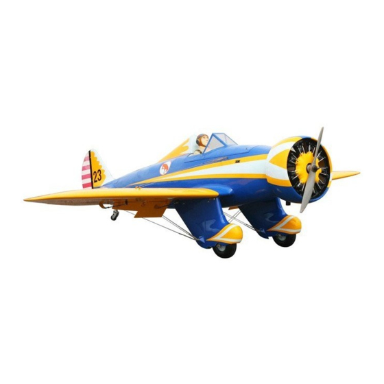
P-26A PEASHOOTER
Code: SEA305
" Graphics and specifications may change without notice " .
Specifications:
Wingspan---------------71 in (180 cm).
Wing area---------------965.7 sq.in ( 62.3 sq.dm).
Weight-------------------13.7 -14.1 lbs (6.2 - 6.4kg).
Length-------------------62.2 in (158 cm).
Engine-------------------30cc gasoline.
Radio--------------------6 channels with 8 servos.
1
Advertisement
Table of Contents

Related Manuals for Seagull Models P-26A PEASHOOTER


Summary of Contents for Seagull Models P-26A PEASHOOTER
- Page 1 A S S E M B L Y M A N U A L P-26A PEASHOOTER Code: SEA305 “ Graphics and specifications may change without notice ” . Specifications: Wingspan---------------71 in (180 cm). Wing area---------------965.7 sq.in ( 62.3 sq.dm). Weight-------------------13.7 -14.1 lbs (6.2 - 6.4kg).
-
Page 2: Kit Contents
You will find that most of the work has been done for you already. The motor mount has been fitted and the hinges are pre-installed. Flying the P-26A PEASHOOTER is simply a joy. This instruction manual is designed to help you build a great flying aeroplane. Please read this manual throughly before starting assembly of your P-26A PEASHOOTER . -
Page 3: Additional Items Required
HINGING THE FLAP. KIT CONTENTS. SEA305 P-26A PEASHOOTER 1. Fuselage 2. Wing set 3. Tail set 4. Cowling 5. Windshield and pilot 6. Wheel pants 2x10mm 7. Landing gear 8. Dummy engine 2x10mm ADDITIONAL ITEMS REQUIRED. 30cc gasoline engine. �... -
Page 4: Installing The Aileron Servos
P-26A Peashooter Instruction Manual. Epoxy. Aileron control horn. Repeat this process with the other wing INSTALLING THE AILERON SERVOS. panel, securely hinging the flap in place. INSTALL THE AILERONS CONTROL HORN. Flap control horn Aileron control horn Elevator and rudder... - Page 5 6) Apply 1-2 drops of thin C/A to each of the mounting tabs. Allow the C/A to cure 2) Use drill bit in a pin vise to drill the without using accelerator. mouting holes in the blocks. C/A glue 7) Remove the string from the wing at the 3) Apply 2-3 drops of thin C/A to each servo location and use the tape to attach it of the mounting holes.
-
Page 6: Aileron Pushrod Installation
P-26A Peashooter Instruction Manual. AILERON PUSHROD INSTALLATION. Please see below pictures. 100mm 8) Set the aileron hatch in place and use a Phillips screw driver to install it with four M3 lock nut. M3 clevis. wood screws. M2x10mm INSTALL FLAP CONTROL HORN. -
Page 7: Installing The Flap Servos
FLAP PUSHROD INSTALLATION. Repeat the procedure as for the aileron pushrod. Fiberglass control horn 100mm Epoxy. M3 lock nut. M3 clevis. Epoxy. INSTALLING THE FLAP SERVOS. General picture : Repeat the procedure for the flap servo. -
Page 8: Top View
P-26A Peashooter Instruction Manual. Epoxy. TOP VIEW Epoxy. BOTTOM VIEW Epoxy. -
Page 9: Installing The Main Landing Gear
INSTALLING THE MAIN LANDING GEAR. Epoxy. - Page 10 P-26A Peashooter Instruction Manual. Fill Epoxy. C/A glue. 3x15mm...
- Page 11 Note : You need to rotate wheel pant, then push down. Next step, rotate wheel pant back to fit landing gear and mark on it for cutting.
- Page 12 P-26A Peashooter Instruction Manual. 3x15mm 3x10mm Drill hole on wheel pant, you can do as below pictures. 3x10mm...
- Page 13 Collar. Collar. Collar.
-
Page 14: Installing The Fuselage Servos
P-26A Peashooter Instruction Manual. Throttle servo. Elevator servo. Rudder servo. Elevator servo. THROTTLE SERVO ARM INSTALLATION. Install adjustable servo connector in the servo arm as same as picture below: Loctite secure. Adjustable servo connector. Servo arm. Throttle servo arm. Elevator servo arm. -
Page 15: Installing The Stopper Assembly
INSTALLING THE STOPPER 3/32” Hole. ASSEMBLY. 1) Using a modeling knife, carefully cut off the rear portion of one of the 3 nylon tubes leaving 1/2” protruding from the rear of the stopper. This will be the fuel pick up tube. 2) Using a modeling knife, cut one length Trim and cut. -
Page 16: Fuel Tank Installation
P-26A Peashooter Instruction Manual. 4) Test fit the stopper assembly into the tank. It may be necessary to remove some of the flashing around the tank opening using a modeling knife. If flashing is present, make sure none falls into the tank. -
Page 17: Mounting The Engine
Blow through one of the lines to en- M5x90mm sure the fuel lines have not become kinked inside the fuel tank compartment. Air should flow through easily. MOUNTING THE ENGINE. Please see pictures below Locate the engine mounting in position on the firewall. - Page 18 P-26A Peashooter Instruction Manual. Use thread locker glue for each blind nut. M5x90mm...
- Page 19 Reinstall the servo horn by sliding the connector over the pushrod wire. Cent- er the throttle stick and trim and install the servo horn perpendiular to the servo center line. Attach the muffler to the engine using the hardware included with the muffler. Move the throttle stick to the closed po- sition and move the carburetor to closed.
- Page 20 P-26A Peashooter Instruction Manual. DUMMY ENGINE.
- Page 21 COWLING. M3x15mm Epoxy...
- Page 22 P-26A Peashooter Instruction Manual. Mark and drill hole as shown to adjust gasoline clock. M3x15mm...
- Page 23 ELECTRIC POWER CONVERSION. 1) Locate the items neccessary to install the electric power conversion included with your model. Use a drill bit to drill the holes necessary to mount your particular motor choice. M5x25mm 4) Attach the motor to the front of the electric motor box using four 4mm blind nut, four M4x20mm hex head bolts to se- cure the motor.
- Page 24 P-26A Peashooter Instruction Manual. Then, use 5.5mm drill bit to enlarge the holes on the electric motor box. Balsa stick. Epoxy 5.5mm 5) Attach the speed control to the side of the motor box using two-sided tape and tie wraps. Connect the appropriate leads from the speed control to the mo- tor.
-
Page 25: Installing Vertical Stabilizer
The propeller should not touch any part of the spinner cone. If it does, use a sharp modeling knife and carefully trim away the spinner cone where the propel- Battery. ler comes in contact with it. Open the air exit hole. INSTALLING VERTICAL STABILIZER 1) Using a modeling knife, remove the covering from over the precut hinge slot... - Page 26 P-26A Peashooter Instruction Manual. 2) Using a modeling knife, carefully re- move the covering at mounting slot of vertical stabilizer. 5) When you are sure that everything is aligned correctly, mix up a generous amount of Flash 30 Minute Epoxy. Ap- ply epoxy to the bottom and top edges of the filler block.
- Page 27 Epoxy INSTALL ELEVATOR CONTROL HORN. Fiberglass control horn Epoxy. Elevator fiberglass control horn. Epoxy. Use scotch tape to avoid pushrod drop out.
-
Page 28: Elevator Pushrod Installation
P-26A Peashooter Instruction Manual. Epoxy. Epoxy. Attach the aluminum tube to combine two elevator as below pictures. ELEVATOR PUSHROD INSTALLATION. 1) Install the elevator control horn using the same method as with the aileron con- trol horns. 2) Position the elevator control horn on the both side of elevator. -
Page 29: Rudder Pushrod Installation
765mm 855mm M2 lock nut. M2 clevis. M2 lock nut. M2 clevis. MOUNTING THE TAIL WHEEL. RUDDER PUSHROD INSTALLATION. Locate items necessary to imstall tail Repeat steps as same as steps done for gear. elevator pushrod. - Page 30 P-26A Peashooter Instruction Manual. Nose wheel steering arm. 725mm M2 lock nut. M2 clevis. Metal clevis. Epoxy...
- Page 31 ATTACHMENT WING- FUSELAGE. Attach the aluminium tube into fuselage. Epoxy Wing tube. Insert two wing panels as pictures below. Wing bolt TOP VIEW. INSTALLATION WING STRUTS.
- Page 32 P-26A Peashooter Instruction Manual.
- Page 33 BOTTOM VIEW...
- Page 34 P-26A Peashooter Instruction Manual. INSTALLATION GEAR STRUTS. INSTALLATION PILOT AND WINDSHIELD. 1) Locate items necessary to install pilot and windshield. 2) A scale pilot is included with this ARF. The Pilot included fits well in the cockpit. (or you can order others scale pilot fig- ures made by SG Models.
-
Page 35: Apply The Decals
3) Position the pilot figure on the cock- INSTALLING BATTERY - RECEIVER. pit floor as shown. Use epoxy to glue the base of the pilot figure, please see pictures 1) Plug the servos leads and the switch- as shown. lead into the receiver. Plug the battery pack lead into the switch also. -
Page 36: Control Throws
P-26A Peashooter Instruction Manual. Moving the balance forward may im- prove the smoothness and arrow- like tracking, but it may then require more speed for take off and make it more dif- 120mm ficult to slow down for landing. Moving the balance aft makes the model more agile with a lighter and snappier ”feel”. -
Page 37: Flight Preparation
2) Check every bolt and every glue A) Plug in your radio system per the joint in the P-26A PEASHOOTER manufacturer’s instructions and turn ensure that everything is tight and everything on. well bonded. - Page 38 P-26A Peashooter Instruction Manual. If you have any queries, or are interested in our products, please feel free to contact us Factory : 12/101A - Hamlet 4 - Le Van Khuong Street - Dong Thanh Ward - Hoc Mon District - Ho Chi Minh City - Viet Nam.
Need help?
Do you have a question about the P-26A PEASHOOTER and is the answer not in the manual?
Questions and answers