Table of Contents
Advertisement
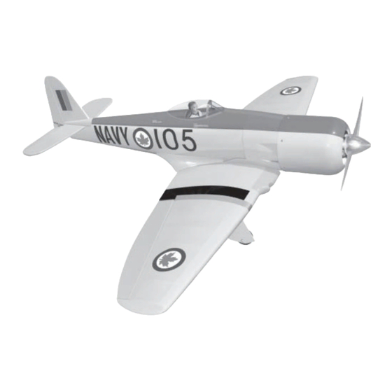
SEA FUR
SEA FUR Y Y Y Y Y
SEA FUR
SEA FUR
SEA FUR
Specifications:
Wingspan----------------------------------------- 66 in------------------------ 167.5cm.
Wing area----------------------------------- 842 sq.in------------------- 54.3 sq.dm.
Approximate flying weight------------------ 9.5 lbs--------------------------- 4.3kg.
Length-------------------------------------------------- 59 in---------------------------- 150cm.
Recommended engine size------.91 - 1.20 cu.in------------------------- 2-stroke.
Recommended R/C ----------------------------- 6 channels with 9 digital servos.
Flying skill level ------------------------------------------- Advanced/Intermediate.
Kit features.
•
Ready-made—minimal assembly & finishing required.
•
Ready-covered—including decals, trim & covering.
•
Factory-installed pushrod.
•
Comprehensive hardware pack including wheels, tank, parts, undercarriage.
•
Photo-illustrated step-by-step Assembly Manual.
ASSEMBLY MANUAL
-------.91- 1.20 cu.in-------------------- 4-stroke.
Made in Vietnam.
Advertisement
Table of Contents

Related Manuals for Seagull Models SEA FURY


Summary of Contents for Seagull Models SEA FURY
- Page 1 SEA FUR SEA FUR Y Y Y Y Y SEA FUR SEA FUR SEA FUR ASSEMBLY MANUAL Specifications: Wingspan----------------------------------------- 66 in------------------------ 167.5cm. Wing area----------------------------------- 842 sq.in------------------- 54.3 sq.dm. Approximate flying weight------------------ 9.5 lbs--------------------------- 4.3kg. Length-------------------------------------------------- 59 in---------------------------- 150cm. Recommended engine size------.91 - 1.20 cu.in------------------------- 2-stroke. -------.91- 1.20 cu.in-------------------- 4-stroke.
- Page 2 This instruction manual is designed to help you build a great flying aeroplane. Please read this manual thoroughly before starting assembly of your SEA FURY . Use the parts listing below to identify all parts.
- Page 3 This will ensure proper as- sembly as the SEA FURY is made from natural materials and minor ad- justments may have to be made. The paint and plastic parts used in this kit are fuel proof.
- Page 4 SEA FURY. Instruction Manual. There are 2 options for colour scheme for SEA FURY: 1. Option 1: Standard colours (Silver). 2. Option 2: Blue and White colour, you should use black pen (fuel proof) to draw the panel lines on the airplane as same as pictures below.
- Page 5 SEA FURY. Instruction Manual.
-
Page 6: Hinging The Ailerons
SEA FURY. Instruction Manual. HINGING THE AILERONS. Note: The control surfaces, including the T-pin. ailerons, elevators, and rudder, are prehinged with hinges installed, but the hinges are not glued in place. It is imperative that you properly adhere the hinges in place per the steps that follow using a high-quality thin C/A glue. -
Page 7: Hinging The Rudder
SEA FURY. Instruction Manual. HINGING THE RUDDER. Glue the rudder hinges in place using the same tectniques used to hinge the ailerons. C/A glue. ! 6) Using C/A remover/debonder and a paper towel, remove any excess C/A glue that may have accumulated on the wing or in the aileron hinge area. - Page 8 SEA FURY. Instruction Manual. INSTALLING RETRACTABLE Plastic wheel cover. Cut. SERVO. Metal connector. Drill hole diameter 15mm. Servo arm. Metal clevis. Pushrod. Servo for retractable only. M2 lock. Remove covering. C/A glue. 3 x 12mm. Remove covering. Repeat procedure for orther landing...
-
Page 9: Installing The Main Gear Wheels
SEA FURY. Instruction Manual. 2 x 8mm. Plywood. INSTALLING THE MAIN GEAR WHEELS. Cut. Epoxy. 2 x 8mm. - Page 10 SEA FURY. Instruction Manual. Cut. Using a small weight ( Weighted fuel pick-up ) and thread, feed the string through works well Sanding. the wing as indicated. Small weight. Thread. Wing bottom. INSTALLING THE FLAP SERVO. Electric wire. Small weight.
- Page 11 SEA FURY. Instruction Manual. INSTALLING THE FLAP SERVO CONTROL HORN. Flap mount. Electric wire. Flap. ! 1) Put the flap in flap mount. ! 2) Using a ruler & pen to draw a straight line as pictures below. Plastic tape.
- Page 12 SEA FURY. Instruction Manual. ! 3) Locate the nylon control horns,nylon control horn backplates and three machine screws. ! 4) Position the flap horn on the bottom side of flap. Bottom flap. C/A glue. 2 x 20mm. Flap servo. T-pins.
-
Page 13: Wing Assembly
SEA FURY. Instruction Manual. WING ASSEMBLY. Pen. NOTE: We highly recommend using 30 minute epoxy as it is stronger and provides more working time, allowing the builder to properly align the parts. Using fast cure epoxy when joining Mark point. -
Page 14: Installing The Aileron Servos
SEA FURY. Instruction Manual. We recommended to use long servos arm for all servos without throttle servo. ! 1) Install the rubber grommets and brass collets onto the aileron servo. Test fit the servo into the aileron servo mount. Because the size of servos differ, you Epoxy. -
Page 15: Installing The Aileron Linkage
SEA FURY. Instruction Manual. Attach the thread to the servo lead and carefully thread it though the wing. Once you have thread the lead throught the wing, remove the string so it can use for the other servo lead. Tape the servo lead to the wing to prevent it from falling back into the wing. - Page 16 SEA FURY. Instruction Manual. 12mm. ! 2) Locate the nylon control horns,nylon control horn backplates and three machine screws. ! 3) Position the aileron horn on the bottom Pen. Mark point. side of aileron. 2 x 30mm. M3 lock nut.
-
Page 17: Installing The Engine Mount
SEA FURY. Instruction Manual. INSTALLING THE ENGINE MOUNT. See pictures below: 4 x 30mm. ! 4) Carefully heat the vent tube using a heat gun or lighter to permanently set the angle of the tube. Vent tube. Fuel Pick up FUEL TANK. -
Page 18: Mounting The Engine
SEA FURY. Instruction Manual. ! 6) With the stopper assembly in place, Fuel tank. the weighted pickup should rest away from the rear of the tank and move freely inside the tank. The top of the vent tube should rest just below the top of the tank. - Page 19 SEA FURY. Instruction Manual. ! 4) Remove the engine. Using an drill bit, COWLING. drill the mounting holes through the engine ! 1) Slide the fiberglass cowl over the en- mount at the four locations marked. gine and line up the back edge of the cowl with the marks you made on the fuselage.
- Page 20 SEA FURY. Instruction Manual. ! 3) Install the muffler and muffler extension onto the engine and make the cutout in the cowl for muffler clearance. Connect the fuel and pressure lines to the carburetor, muffler 3x10mm. and fuel filler valve. Secure the cowl to fuse- lage using the 3x10mm screws.
-
Page 21: Installing The Spinner
SEA FURY. Instruction Manual. ! 3) Make a push-pull lever out of scrap wire. INSTALLING THE SPINNER. Attach the wire to the switch lever and route Not included. the wire out the side of the fuselage, through the hole you drilled. -
Page 22: Aligning The Horizontal Stabilizer
SEA FURY. Instruction Manual. HORIZONTAL STABILIZER. ALIGNING THE HORIZONTAL STABILIZER. Remove covering. ! 5) When you are satisfied with the align- ment, hold the stabilizer in place with T- pins or masking tape, but do not glue at this time. -
Page 23: Aligning The Vertical Stabilizer
SEA FURY. Instruction Manual. ALIGNING THE VERTICAL STABILIZER. Remove covering. When cutting through the covering to remove it, cut with only enough pressure to only cut through the covering itself. Cut- ting into the balsa structure may weaken ! 8) Using a modeling knife, carefully re- Remove covering. -
Page 24: Control Horn Installation
SEA FURY. Instruction Manual. ! 3) When you are sure that everything is aligned correctly, mix up a generous amount of Flash 30 Minute Epoxy. Apply a thin layer to the fuselage and to the sides and bottom of the vertical stabilizer mounting area. - Page 25 SEA FURY. Instruction Manual. Elevator control horn. Rudder control horn. Elevator Elevator control horn. control horn. Rudder control horn. Adjustable Servo ELEVATOR - RUDDER PUSHROD INSTALLATION. connector. ! 1) Elevator and rudder pushrods assembly Servo arm. follow pictures below. Control horn.
- Page 26 SEA FURY. Instruction Manual. ! 4) Secure the tail wheel bracket in place MOUNTING THE TAIL WHEEL. using two 3x25mm wood screws. Be careful not to overtighten the screws. 33mm. ! 1) You have to trim each axles and using a tool cutting and cut-off wheel.
-
Page 27: Wing Fillet Installation
SEA FURY. Instruction Manual. C/A glue. 2 x 8mm (4pcs). WING FILLET INSTALLATION. See pictures below: ATTACHMENT WING-FUSELAGE. Remove covering. Right wing. Left wing. C/A glue. -
Page 28: Control Throws
CONTROL THROWS. C/A glue. ! 1) We highly recommend setting up the SEA FURY using the control throws listed at right. We have listed control throws for both Low Rate (initial test flying/sport flying) and High Rate (aerobatic flying). -
Page 29: Flight Preparation
! 2) Check every bolt and every glue joint in the SEA FURY to ensure that everything is tight and well bonded. ! 3) Double check the balance of the air- plane.
Need help?
Do you have a question about the SEA FURY and is the answer not in the manual?
Questions and answers