Table of Contents
Advertisement
Quick Links
MS: 143
ASSEMBLY MANUAL
"Graphics and specifications may change without notice".
Specifications:
Wing span -----------------------------63in (160cm).
Wing area ---------------722.3sq.in (46.6sq dm).
Weight ----------------------8.8-9.7lbs (4.0-4.4kg).
Length -----------------------------54.5in (138.5cm).
Engine -------------0.61-0.75 cu.in -----2-stroke.
0.91-1.25cu.in -----4-stroke.
Radio ---------- 4 channels with 5 digital servos.
Electric conversion: optional.
Advertisement
Table of Contents

Subscribe to Our Youtube Channel
Related Manuals for Seagull Models Shoestring SEA143


Summary of Contents for Seagull Models Shoestring SEA143
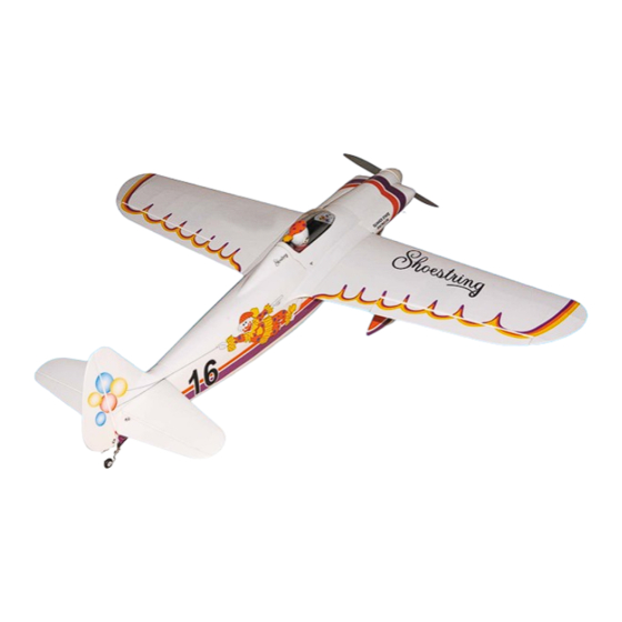
- Page 1 MS: 143 ASSEMBLY MANUAL “Graphics and specifications may change without notice”. Specifications: Wing span -----------------------------63in (160cm). Wing area ---------------722.3sq.in (46.6sq dm). Weight ----------------------8.8-9.7lbs (4.0-4.4kg). Length -----------------------------54.5in (138.5cm). Engine -------------0.61-0.75 cu.in -----2-stroke. 0.91-1.25cu.in -----4-stroke. Radio ---------- 4 channels with 5 digital servos. Electric conversion: optional.
-
Page 2: Kit Contents
SHOETRING. INTRODUCTION. Thank you for choosing the SHOETRING ARTF by SEAGULL MODELS COMPANY LTD. The SHOETRING was designed with the intermediate/advanced sport scale in mind. It is a semi scale airplane which is easy to fly and quick to assemble. The airframe is conventionally built using balsa, plywood to make it stronger than the average ARTF , yet the design allows the aeroplane to be kept light. -
Page 3: Hinging The Ailerons
www.seagullmodels.com KIT CONTENTS HINGING THE AILERONS. SEA14301 Fuselage Note: The control surfaces, including the SEA14302 Wing set ailerons, elevators, and rudder, are SEA14303 Tail set prehinged with hinges installed, but the SEA14304 Fiberglass cowl hinges are not glued in place. It is SEA14305 Landing gear imperative that you properly adhere the... -
Page 4: Hinging The Elevator
Instruction Manual SHOETRING. 5) Turn the wing panel over and deflect the aileron in the opposite direction from the opposite side. Apply thin C/A glue to each hinge, making sure that the C/A penetrates into 4)Deflect the aileron and completely both the aileron and wing panel. -
Page 5: Hinging The Rudder
www.seagullmodels.com INSTALL ELEVATOR CONTROL HORN. HINGING THE RUDDER. Glue the rudder hinges in place using the Fiberglass control horn same techniques used to hinge the ailerons. Hinge INSTALL AILERON CONTROL HORN. Fiberglass control horn Elevator control horn INSTALL RUDDER CONTROL HORN. Fiberglass control horn Aileron control horn... -
Page 6: Installing The Stopper Assembly
Instruction Manual SHOETRING. INSTALLING THE STOPPER ASSEMBLY. 1) Using a modeling knife, carefully cut off the rear portion of one of the 3 nylon tubes leaving 1/2” protruding from the rear of the stopper. This will be the fuel pick up tube. 2) Using a modeling knife, cut one length of silicon fuel line. -
Page 7: Fuel Tank Installation
www.seagullmodels.com You should mark which tube is the vent and which is the fuel pickup when you attach fuel tubing to the tubes in the stopper. Once the tank is installed inside the fuselage, it may be difficult to determine which is which. 7) Slide the fuel tank into the fuselage. - Page 8 Instruction Manual SHOETRING. 4) Slide the collar to the axle and setscrew Pushrod wire. the collars to secure the collar to the axle and then slider the wheel on the axle with a drop of oil on the axle so the wheel will spin freely when installed.
- Page 9 www.seagullmodels.com INSTALLING THE MAIN LANDING GEAR Landing Gear. TO FUSELAGE. wheel Pant. 8) The blind nuts for securing the landing gear are already mounted inside the fuselage. C/A glue. 9) Using the hardware provided, mount the main landing gear to the fuselage. 10) Place the fuselage inverted on the workbench in a suitable stand.
- Page 10 Instruction Manual SHOETRING. Because the size of servos differ, you may need to adjust the size of the precut open- ing in the mount. The notch in the sides of the mount allow the servo lead to pass through. 1) Using a small weight ( Weighted fuel pick-up ) and string, feed the string through works well...
- Page 11 www.seagullmodels.com 9) Set the aileron hatch in place and use a Phillips screw driver to install it with four wood screws. INSTALLING THE FUSELAGE SERVO. Because the size of servos differ, you may need to adjust the size of the precut open- ing in the mount.
-
Page 12: Mounting The Engine
Instruction Manual SHOETRING. THROTTLE SERVO ARM INSTALLATION. Install adjustable servo connector in the servo arm as same as picture below: Switch. Loctite secure. Adjustable Servo connector. Servo arm. MOUNTING THE ENGINE. 1 PCS. ENGINE .61 - .75 : 2 STROKE. 1) Position the engine with the drive washer (135mm) forward of the firewall as shown. - Page 13 www.seagullmodels.com 4) On the fire wall has the location for the throttle pusshrod tube (pre-drill). 5) Slide the pushrod tube in the firewall and 9) Move the throttle stick to the closed position guide it through the fuel tank mount. Use and move the carburetor to closed.
- Page 14 Instruction Manual SHOETRING. 3.5mm. Machine Screw M3x40mm. Pushrod wire. 3) Use a drill to drill the four holes in the engine mount rails. 8) Reinstall the servo horn by sliding the connector over the pushrod wire. Center the throttle stick and trim and install the servo horn 4.2mm diameter.
-
Page 15: Cowling Installation
www.seagullmodels.com Because of the size of the cowl, it may be nec- COWLING INSTALLATION. essary to use a needle valve extension for the high speed needle valve. Make this out of suf- 1) Slide the fiberglass cowl over the ficient length 1.5mm wire and install it into the engine and line up the back edge of the cowl end of the needle valve. - Page 16 Instruction Manual SHOETRING. 2) Attach the electric motor box to the firewall suitable with the cross lines drawn on the electric motor box and firewall. Using epoxy and balsa stick to secure the motor box to the firewall. Please see pictures below. Machine Screw M3x10mm Epoxy.
-
Page 17: Spinner Installation
www.seagullmodels.com 4) Locate the plywood battery tray to the fuselage. Tighten the screws using machine screws M3x15mm to secure the tray in position. 4mm. Battery. Blind nut. M4x15mm. M4x15mm. 5) Attach the speed control to the side of the motor box using two-sided tape and tie wraps. Connect the appropriate leads from the speed control to the motor. -
Page 18: Installing The Horizontal Stabilizer
Instruction Manual SHOETRING. The propeller should not touch any part of the spinner cone. If it does, use a sharp modeling knife and carefully trim away 70mm. the spinner cone where the propeller comes in contact with it. M3 clevis. M3 lock nut. - Page 19 www.seagullmodels.com Remove covering. Pen. 3) Put the stabilizer into place in the po- sition of the fuselage. 4) Install the stabilizer onto the fuselage. Align the centerline drawn on the top and the 7) Remove the stabilizer. Using the lines rear of the stabilizer with the centre of the fu- you just drew as a guide, carefully remove the selage.
-
Page 20: Installing The Vertical Stabilizer
Instruction Manual SHOETRING. While holding the vertical stabilizer firmly in place, use a pen and draw a line on each side of the vertical stabilizer where it meets the top of the fuselage. 3) Slide the vertical stabilizer back in place. - Page 21 www.seagullmodels.com 652mm. Cut. Elevator pushrod. Control horn. ELEVATOR PUSHROD HORN INSTALLATION. 1) Install the elevator control horn using M2 lock nut. Metal clevis. the same method as with the aileron control horns. 2) Position the elevator control horn on the both side of elevator. 8mm.
-
Page 22: Mounting The Tail Wheel
Instruction Manual SHOETRING. Plastic part. Elevator pushrod. RUDDER PUSHROD HORN INSTALLATION. 735mm. C/A glue. Rudder pushrod. M2 clevis. M2 lock nut. 765 mm. Elevator pushrod. Elevator pushrod. Control horn. C/A glue. M2 lock nut. Metal clevis. Rudder pushrod. Rudder control horn. Elevator control horn. - Page 23 www.seagullmodels.com M3 x 12mm. Epoxy . INSTALLATION PILOT. 1) A scale pilot is included with this ARF. The Seagull Pilot included fitting well to the cockpit. (or you can order others scale pilot figures made by Seagull factory. They are available at Seagull distributors.) If you are going to install a pilot figure, please use a sanding bar to sand the base of the figure...
-
Page 24: Apply The Decals
Instruction Manual SHOETRING. APPLY THE DECALS. 1) If all the decals are precut and ready to stick. Please be certain the model is clean and free from oily fingerprints and dust. Position decal on the model where desired, using the photos on the box and aid in their location. - Page 25 www.seagullmodels.com Attach the aluminium tube into fuselage. Wing tube. Insert two wing panels as pictures below. BALANCING. 1) It is critical that your airplane be balanced correctly. Improper balance will cause your plane to lose control and crash. THE CENTER OF GRAVITY IS LOCATED 94 MM BACK FROM THE LEADING EDGE OF THE WING AT THE WING ROOT.
-
Page 26: Control Throws
Instruction Manual SHOETRING. Accurately mark the balance point on the top *If possible, first attempt to balance the model of the wing on both sides of the fuselage. The by changing the position of the receiver battery balance point is located 94 mm back from the and receiver. -
Page 27: Flight Preparation
www.seagullmodels.com PREFLIGHT CHECK. FLIGHT PREPARATION. 1) Completely charge your transmitter A) Check the operation and direction of and receiver batteries before your first day of the elevator, rudder, ailerons and throttle. flying. Plug in your radio system per the 2) Check every bolt and every glue joint manufacturer's instructions and turn every- in the SHOETRING to ensure that everything thing on.
Need help?
Do you have a question about the Shoestring SEA143 and is the answer not in the manual?
Questions and answers