Table of Contents
Advertisement
Quick Links
Code : SEA 324Y
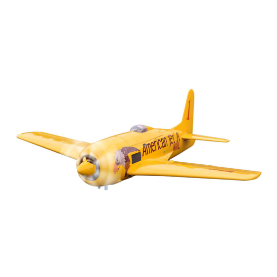
ASSEMBLY MANUAL
Speciications:
Wingspan--------------- 71.0 in (180.3 cm).
Wing area--------------- 1147.0sq.ins (74.0 sq.dm).
Weight------------------- 14.3-15.0 lbs (6.5-6.8 kg).
Length------------------- 62.7 in (159.2 cm).
Engine/Motor size----- 33-45cc gasoline.
Radio--------------------- 8 channels with 10 servos.
1
Advertisement
Table of Contents

Subscribe to Our Youtube Channel
Related Manuals for Seagull Models SEA 324Y


Summary of Contents for Seagull Models SEA 324Y
- Page 1 Code : SEA 324Y ASSEMBLY MANUAL Speciications: Wingspan--------------- 71.0 in (180.3 cm). Wing area--------------- 1147.0sq.ins (74.0 sq.dm). Weight------------------- 14.3-15.0 lbs (6.5-6.8 kg). Length------------------- 62.7 in (159.2 cm). Engine/Motor size----- 33-45cc gasoline. Radio--------------------- 8 channels with 10 servos.
-
Page 2: Kit Contents
Instruction Manual. GRUMMAN F8F BEARCAT INTRODUCTION hank you for choosing the GRUMMAN F8F BEARCAT ARTF by SG MODELS . he GRUMMAN F8F BEARCAT was designed with the intermediate/advanced sport lyer in mind. It is a semi scale airplane which is easy to ly and quick to assemble. he airframe is conventionally built using balsa, plywood to make it stronger than the av- erage ARTF, yet the design allows the aeroplane to be kept light. -
Page 3: Additional Items Required
KIT CONTENTS INSTALL THE AILERONS CONTROL HORN SEA324 GRUMMAN F8F BEARCAT 1. Fuselage 2. Wing set (2) 3. Tail set (2) 4. Canopy 5. Cowling 6. Wing tube 7. Pilot 8. landing gear Fiberglass control horn 9. Fuel tank 10. Tail wheel 11. -
Page 4: Installing The Aileron Servos
Instruction Manual. GRUMMAN F8F BEARCAT INSTALLING THE AILERON SERVOS Use drill bit in a pin vise to drill the mout- ing holes in the blocks. 1.5mm Apply 2-3 drops of thin C/A to each of the mounting holes. Allow the C/A to cure without using accelerator. - Page 5 Secure the servo to the aileron hatch us- ing Phillips screwdriver and the screws provided with the servo. Apply 1-2 drops of thin C/A to each of the mounting tabs. Allow the C/A to cure without using accelerator. C/A glue Remove the string from the wing at the servo location and use the tape to attach it to the servo extension lead.
- Page 6 Instruction Manual. GRUMMAN F8F BEARCAT INSTALLING THE FLAP PUSHROD AILERON PUSHROD INSTALLATION Please see below pictures. Please see below pictures. 80mm. 80mm.
- Page 7 Attach the lap servo to the lap servo Attach the clevis to the lap servo arm. cover. Center the lap servo (or set the values to 0 for both up and down) and in- stall the servo arm perpendicular to the servo centerline.
- Page 8 Instruction Manual. GRUMMAN F8F BEARCAT Once adjusted, make sure all clevis re- Trim the lap linkage cover using a hobby tainers are in position. Apply a drop of knife and hobby scissors. threadlock near the clevis, then tighten the nut against the clevis to keep the link- age from changing length inside the wing.
-
Page 9: Installing Landing Gear
Mark. INSTALLING LANDING GEAR Servo Landing Gear. 2.5mm. Mininum servo spec. Torque : 222 oz-in (16 kg-cm) @ 4.8V; 278 oz-in (20 kg-cm) @ 6.0V Locate items necessary to install Sprin Landing Gear. Install servo for Retractable landing gear. M3x12mm... - Page 10 Instruction Manual. GRUMMAN F8F BEARCAT Collar. M3x4mm. Collar. Slide the wheel on the axle, then secure it using the wheel collar. M3x4mm. Secure the landing gear doors to the landing gear struts.
- Page 11 M3x12mm 3x12mm. 3x8mm. M3x8mm...
-
Page 12: Installing The Fuselage Servos
Instruction Manual. GRUMMAN F8F BEARCAT Install adjustable servo connector in the servo arm as same as picture below: hrottle servo arm. Rudder servo arm. Elevator servo arm . INSTALLING THE FUSELAGE SERVOS Because the size of servos difer, you may need to adjust the size of the precut INSTALLING THE RECEIVER SWITCH opening in the mount. -
Page 13: Installing The Stopper Assembly
Using a modeling knife, cut one length of silicon fuel line. Connect one end of the line to the weighted fuel pick up and the other end to the nylon pick up tube. Switch. INSTALLING THE ENGINE SWITCH Trim and cut. Vent tube. -
Page 14: Fuel Tank Installation
Instruction Manual. GRUMMAN F8F BEARCAT With the stopper assembly in place, the weighted pick-up should rest away from the rear of the tank and move freely inside the tank. he top of the vent tube should rest just below the top of the tank. It should not touch the top of the tank. -
Page 15: Mounting The Engine
MOUNTING THE ENGINE Please see below pictures. 160mm 5x60mm Ignition Modude. - Page 16 Instruction Manual. GRUMMAN F8F BEARCAT Pushrod wire. Move the throttle stick to the closed posi- tion and move the carburetor to closed. Use a 2.5mm hex wrench to tighten the screw that secures the throttle pushrod wire. Make sure to use threadlock on the screw so it does not vibrate loose.
- Page 18 Instruction Manual. GRUMMAN F8F BEARCAT Tape the cowl to the fuselage using low- tack tape. Use a drill and drill bit to drill the holes for the cowl mounting screws. Make sure the cowl position is correct before drill- ing each hole. Install the muler and muler extension onto the engine and make the cutout in the cowl for muler clearance.
- Page 19 Nylon screw 4x25mm. ELECTRIC POWER CONVERSION Locate the items neccessary to install the electric power conversion included with your model. Recommend the items necessary to install the electric power conversion parts included with your model. - Motor: 160 - 2700 Watts - Propeller: 18x8 ~ 20x10 - ESC: 70A - 100A - 9S- 10S Lipo...
- Page 20 Instruction Manual. GRUMMAN F8F BEARCAT hen, use 5.5mm drill bit to enlarge the holes on the electric motor box. 5.5mm M5x25mm and washers. Attach the motor to the front of the elec- Blind nut. tric motor box using four 4mm blind nut, four M4x25mm hex head bolts to secure the motor.
-
Page 21: Installing The Spinner
Speed control. 160mm 4x20mm Tie-wraps. Battery. Balsa stick. Epoxy. INSTALLING THE SPINNER Install the spinner backplate, propeller and spinner cone. 6) Attach the speed control to the side of the motor box using two-sided tape and tie wraps. Connect the appropriate leads from the speed control to the mo- tor. - Page 22 Instruction Manual. GRUMMAN F8F BEARCAT he propeller should not touch any part of the spinner cone. If it does, use a sharp modeling knife and carefully trim away the spinner cone where the propel- ler comes in contact with it. INSTALL ELEVATOR CONTROL HORN Install the elevator control horn using the same method as same as the aileron...
- Page 23 Install the elevator control horn using INSTALLING HORIZONTAL the same method as same as the aileron STABLLIZER control horns. Fiberglass control horn. Use Epoxy Glue to glue the Horizontal Stabilizer to the fuselage. Horizontal Vertical Stabilizer. Stabilizer. Epoxy.
- Page 24 Instruction Manual. GRUMMAN F8F BEARCAT Elevator pushrod. M2 clevis. Hex nut. Fuel tubing. ELEVATOR PUSHROD HORN INSTALLATION Install the elevator control horn using the same method as with the aileron control horns. Position the elevator control horn on the both side of elevator. Elevator control horn.
-
Page 25: Mounting The Tail Wheel
Locate items necessary to install tail wheel. 930mm. M2 clevis M2 lock nut. 700mm. MOUNTING THE TAIL WHEEL... - Page 26 Instruction Manual. GRUMMAN F8F BEARCAT...
- Page 28 Instruction Manual. GRUMMAN F8F BEARCAT 2x6mm...
- Page 29 ATTCHMENT WING-FUSELAGE Attach the aluminiu, thube into fuselage.
- Page 30 Instruction Manual. GRUMMAN F8F BEARCAT INSTALLATION PILOT AND CANOPY 4x15mm. Locate items necessary to install pilot and canopy. A scale pilot is included with this ARF. he Pilot included itting well to the cockpit. (or you can order others scale pilot igures made by SG Models.
-
Page 31: Apply The Decals
BALANCING It is critical that your airplane be balanced correctly. Improper balance will cause your plane to lose control and crash. THE CENTER OF GRAV- ITY IS LOCATED 170MM BACK FROM THE LEADING EDGE OF THE WING AT THE WING ROOT. Mount the wing to the fuselage. -
Page 32: Control Throws
Instruction Manual. GRUMMAN F8F BEARCAT Lit the model. If the tail drops when you CONTROL THROWS lit, the model is “tail heavy” and you must add weight* to the nose. If the nose Ailerons: Rudder: drops, it is “nose heavy” and you must High Rate : High Rate : add weight* to the tail to balance. -
Page 33: Flight Preparation
FLIGHT PREPARATION PREFLIGHT CHECK Check the operation and direction of the 1) Completely charge your transmit- elevator, rudder, ailerons and throttle. ter and receiver batteries before your irst day of lying. A) Plug in your radio system per the 2) Check every bolt and every glue manufacturer’s instructions and turn eve- joint in the GRUMMAN F8F BEARCAT rything on. - Page 34 Instruction Manual. GRUMMAN F8F BEARCAT If you have any queries, or are interested in our products, please feel free to contact us Factory : 12/101A - Hamlet 4 - Le Van Khuong Street - Dong hanh Ward - Hoc Mon District - Ho Chi Minh City - Viet Nam. Oice : 62/8 Ngo Tat To Street - Ward 19 - Binh hanh District - Ho Chi Minh City - Viet Nam Phone : 848 - 86622289 or 848- 36018777...
Need help?
Do you have a question about the SEA 324Y and is the answer not in the manual?
Questions and answers