Table of Contents
Advertisement
Quick Links
Code : SEA 257M
ASSEMBLY MANUAL
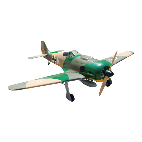
Speciications:
Wingspan---------------80 in (203.3 cm)
Wing area---------------1083.8 sq.in (69.9 sq.dm)
Weight-------------------19.8 lbs (9.0 kg)
Length-------------------62.9 in (159.7 cm)
Engine-------------------50cc
Motor size---------------Power 360
Radio--------------------8 channels with 8 servos
Electric Power Conversion Optional
1
Advertisement
Table of Contents

Related Manuals for Seagull Models Focke-Wulf Fw 190


Summary of Contents for Seagull Models Focke-Wulf Fw 190
- Page 1 Code : SEA 257M ASSEMBLY MANUAL Speciications: Wingspan---------------80 in (203.3 cm) Wing area---------------1083.8 sq.in (69.9 sq.dm) Weight-------------------19.8 lbs (9.0 kg) Length-------------------62.9 in (159.7 cm) Engine-------------------50cc Motor size---------------Power 360 Radio--------------------8 channels with 8 servos Electric Power Conversion Optional...
-
Page 2: Kit Contents
Focke- Wulf FW190 Instruction Manual. INTRODUCTION hank you for choosing the Focke- Wulf FW190 ARTF by SG MODELS . he Focke- Wulf FW190 was designed with the intermediate/advanced sport lyer in mind. It is a semi scale air- plane which is easy to ly and quick to assemble. he airframe is conventionally built using balsa, plywood to make it stronger than the average ARTF, yet the design allows the aeroplane to be kept light. -
Page 3: Additional Items Required
KIT CONTENTS HINGING THE FLAP SEA257M Focke- Wulf FW190 1. Fuselage 2. Wing set (2) 3. Tail set (2) 4. Canopy 5. Cowling 6. Wing tube 7. Pilot 8. landing gear 9. Fuel tank 10. Tail wheel 11. Pushrod set 12. - Page 4 Focke- Wulf FW190 Instruction Manual. INSTALL THE AILERONS Place low-tack tape 1/32 inch (1mm) CONTROL HORN from the control horn slot. his will pre- vent epoxy from getting on the control Locate the aileron and lap control horns. surface when the control horns are glued he taller control horn is used for the ailer- in place.
- Page 5 Apply epoxy to the area of the control horns that ist into the slots. Use enough epoxy so the control horns will be fully bonded to the ied surfaces. Epoxy Fiberglass control horn Before the epoxy fully cures, remove the tape from around the control horn. his will allow the epoxy to low around the control horn, creating a small ilet between the control horn and surface for...
-
Page 6: Installing The Aileron Servos
Focke- Wulf FW190 Instruction Manual. INSTALLING THE AILERON SERVOS Use drill bit in a pin vise to drill the mouting holes in the blocks. 1.5mm Apply 2-3 drops of thin C/A to each of the mounting holes. Allow the C/A to cure without using accelerator. - Page 7 Secure the servo to the aileron hatch using Phillips screwdriver and the screws provided with the servo. Apply 1-2 drops of thin C/A to each of the mounting tabs. Allow the C/A to cure without using accelerator. C/A glue Remove the string from the wing at the servo location and use the tape to attach it to the servo extension lead.
- Page 8 Focke- Wulf FW190 Instruction Manual. M3 clevis M3 lock nut INSTALLING THE FLAP SERVO Repeat the procedure for the lap servo. INSTALLING THE FLAP PUSHROD Repeat the procedure for the aileron pushrod. 75mm AILERON PUSHROD INSTALLATION M3 clevis M3 lock nut Please study images below.
-
Page 9: Landing Gear
INSTALLING RETRACTABLE LANDING GEAR Locate items necessary to install Sprin Landing Gear. You use this fork set JP ER-150-85 degree. head locker glue 3x20mm... - Page 10 Focke- Wulf FW190 Instruction Manual.
- Page 11 INSERT BOMB ONTO THE WING Epoxy...
- Page 12 Focke- Wulf FW190 Instruction Manual. INSERT THE WING GUN ONTO THE WING 3x12mm...
-
Page 13: Wing Assembly
WING ASSEMBLY Epoxy Epoxy... -
Page 14: Installing The Fuselage Servos
Focke- Wulf FW190 Instruction Manual. INSTALLING THE FUSELAGE SERVOS Elevator servo arm Because the size of servos difer, you may need to adjust the size of the precut Rudder servo arm opening in the mount. he notch in the sides of the mount allow the servo lead to pass through. -
Page 15: Installing The Stopper Assembly
Using a modeling knife, cut one length of silicon fuel line. Connect one end of the line to the weighted fuel pick up and the other end to the nylon pick up tube. Switch INSTALLING THE ENGINE SWITCH Trim and cut Vent tube Fuel pick up tube Fuel ill tube... -
Page 16: Fuel Tank Installation
Focke- Wulf FW190 Instruction Manual. When satisied with the alignment of the stopper assembly tighten the 3 x 20mm ma- chine screw until the rubber stopper expands and seals the tank opening. Do not overtight- en the assembly as this could cause the tank to split. - Page 17 5.1mm Locate the laser cut engine mounting template. Align mounting template to front of firewall. Drill a hole for the throttle pushrod. Use a 1/4 bit to drill the engine mounting holes. Remove mounting template from fie wall. Firewall shown with mounting holes drilled ready for engine mounting.
-
Page 18: Mounting The Engine
Focke- Wulf FW190 Instruction Manual. Blow through one of the lines to ensure the fuel lines have not become kinked inside the fuel tank compartment. Air should low through easily. MOUNTING THE ENGINE Please study images below. Reinstall the servo horn by sliding the connector over the pushrod wire. - Page 19 Move the throttle stick to the closed position and move the carburetor to Tape the cowl to the fuselage using closed. low-tack tape. Use a 2.5mm hex wrench to tighten the screw that secures the throttle pushrod wire. Make sure to use threadlock on the screw so it does not vibrate loose.
- Page 20 Focke- Wulf FW190 Instruction Manual. ELECTRIC POWER CONVERSION With the muffler, needle valve, and spark/ glow plug removed from the engine, slide the Locate the items neccessary to install cowl in place over the engine. Temporarily in- the electric power conversion included stall the propeller and spinner in order to find with your model.
- Page 21 - Motor: 360 - 6000 Watts Using mounting bolts and washers mount engine to fiewall. - Propeller: 24x10 ~ 25x12 - ESC: 160A - 200A - 10S- 12S Lipo Attach the electric motor box to the irewall suitable with the cross lines drawn on the electric motor box and ire- wall.
- Page 22 Focke- Wulf FW190 Instruction Manual. hen, use 5.5mm drill bit to enlarge the holes on the electric motor box. Attach the speed control to the side of the motor box using two-sided tape and tie wraps. Connect the appropriate leads from the speed control to the mo- tor.
-
Page 23: Installing The Spinner
INSTALLING THE SPINNER Install the spinner backplate, propeller and spinner cone. he propeller should not touch any part of the spinner cone. If it does, use a sharp modeling knife and carefully trim away the spinner cone where the propel- ler comes in contact with it. - Page 24 Focke- Wulf FW190 Instruction Manual. Test it the hinges into the elevator, INSTALL ELEVATOR CONTROL HORN and then the hinges into the horizontal stabilzer. Ensure that the hinge pockets line up, and that the hinges move freely. Install the elevator control horn using the same method as same as the lap control horns.
- Page 25 INSTALL HINGE FOR RUDDER AND Please study images below. Please study images below. Epoxy INSTALL RUDDER CONTROL HORN Epoxy...
- Page 26 Focke- Wulf FW190 Instruction Manual. INSTALLING HORIZONTAL STABLLIZER Use Epoxy to glue the Horizontal Stabilizer to the fuselage.
-
Page 27: Elevator Pushrod Installation
ELEVATOR PUSHROD INSTALLATION Locate items necessary to install elevator pushrod. Elevator pushrods assembly as pictures below. -
Page 28: Rudder Pushrod Installation
Focke- Wulf FW190 Instruction Manual. Rudder pushrods assembly as pictures below. RUDDER PUSHROD INSTALLATION Locate items necessary to install rudder pushrod. MOUNTING THE TAIL WHEEL Locate items necessary to install tail wheel. - Page 29 Steering arm Tail gear...
- Page 30 Focke- Wulf FW190 Instruction Manual. INSTALLATION PILOT AND CANOPY Locate items necessary to install pilot, seats. 2x8mm...
- Page 31 Position the pilot igure on the canopy loor as shown. Use epoxy to glue the base of the pilot igure to the cockpit loor, please see pictures as shown. C/A glue Epoxy A scale pilot is included with this ARF. he Pilot included itting well to the cockpit.
-
Page 32: Apply The Decals
Focke- Wulf FW190 Instruction Manual. Position the canopy to the fuselage. Trace around the tree canopy and onto the fuselage with a marker. Carefully cut and remove the covering material from the fuselage where the canopy touches, exposing the bare wood. hen screw it in place. - Page 33 INSTALLING BATTERY - RECEIVER Plug the servo leads and the switch lead Wing bolt into the receiver. Plug the battery pack lead into the switch also. Wrap the receiver and battery pack in the protective foam rubber to protect them from vibration. Receiver BALANCING - DO NOT SKIP THIS ! It is critical that your airplane be...
-
Page 34: Control Throws
Focke- Wulf FW190 Instruction Manual. * If possible, irst attempt to balance the CONTROL THROWS model by changing the position of the receiver battery and receiver. If you are unable to obtain good balance by doing Ailerons: Rudder: so, then it will be necessary to add weight High Rate : High Rate : to the nose or tail to achieve the proper... - Page 35 15-20mm 15-20mm 20-25mm Fuselage 20-25mm 12-15mm Wing 12-15mm 30mm 80mm...
-
Page 36: Flight Preparation
Focke- Wulf FW190 Instruction Manual. FLIGHT PREPARATION PREFLIGHT CHECK 1) Completely charge your trans- Check the operation and direction mitter and receiver batteries before of the elevator, rudder, ailerons and your irst day of lying. throttle. 2) Check every bolt and every glue A) Plug in your radio system per the joint in the to en-... - Page 37 If you have any queries, or are interested in our products, please feel free to contact us Factory : 12/101A - Hamlet 4 - Le Van Khuong Street - Dong hanh Ward - Hoc Mon District - Ho Chi Minh City - Viet Nam. Oice : 62/8 Ngo Tat To Street - Ward 19 - Binh hanh District - Ho Chi Minh City - Viet Nam Phone : 848 - 86622289 or 848- 36018777...
Need help?
Do you have a question about the Focke-Wulf Fw 190 and is the answer not in the manual?
Questions and answers