Table of Contents
Advertisement
WWW.SEAGULLMODELS.COM
A S S E M B L Y M A N U A L
" Graphics and specifications may change without notice " .
Code: SEA249
(SEA249M)
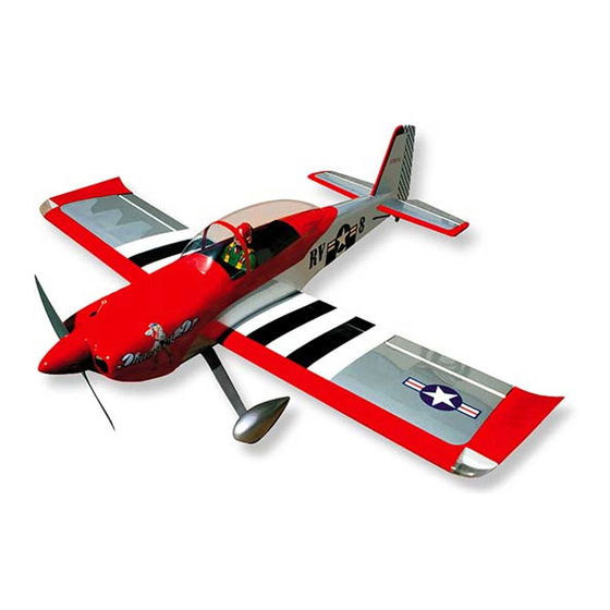
Specifications:
Wingspan---------------70.9 in (180 cm).
Wing area---------------992 sq.in (64 sq.dm).
Weight-------------------11 lbs (5.0 kg).
Length-------------------58 in (147.3 cm).
Gas Engine--------------20cc
Glow Engine------------.91 cu.in
Electric Motor----------1500-2000 watt
( Power 60-110)
Radio--------------------6 channels with 8 servos.
Electric conversion: Optional.
(SEA249D)
www.seagullmodels.com
1
Advertisement
Table of Contents

Subscribe to Our Youtube Channel
Related Manuals for Seagull Models VAN'S RV- 8


Summary of Contents for Seagull Models VAN'S RV- 8
- Page 1 WWW.SEAGULLMODELS.COM A S S E M B L Y M A N U A L “ Graphics and specifications may change without notice “ . Code: SEA249 (SEA249M) Specifications: Wingspan---------------70.9 in (180 cm). Wing area---------------992 sq.in (64 sq.dm). Weight-------------------11 lbs (5.0 kg). Length-------------------58 in (147.3 cm).
-
Page 2: Kit Contents
Instruction Manual. INTRODUCTION. Thank you for choosing the VAN’S RV- 8 ARTF by SEAGULL MODELS COMPANY LTD,. The VAN’S RV- 8 was designed with the intermediate/advanced sport flyer in mind. It is a semi scale airplane which is easy to fly and quick to assemble. The airframe is conventionally built using balsa, plywood to make it stronger than the average ARTF, yet the design allows the aeroplane to be kept light. -
Page 3: Hinging Flap
WWW.SEAGULLMODELS.COM HINGING THE FLAP. KIT CONTENTS. SEA249 VAN’S RV- 8 Note : The control surfaces, including the ai- lerons, elevators, and rudder, are prehinged SEA24901 Fuselage with hinges installed, but the hinges are not glued in place. It is imperative that you prop- SEA24902 Wing set erly adhere the hinges in place per the steps SEA24903 Tail set... -
Page 4: Hinging The Aileron
Van’s RV- 8 Instruction Manual. 4) Deflect the aileron and completely satu- 8) After both ailerons are securely hinged, rate each hinge with thin C/A glue. The ailer- firmly grasp the wing panel and aileron to ons front surface should lightly contact the make sure the hinges are securely glued and wing during this procedure. -
Page 5: Hinging The Elevators
WWW.SEAGULLMODELS.COM 5) Turn the wing panel over and deflect the aileron in the opposite direction from the opposite side. Apply thin C/A glue to each hinge, making sure that the C/A penetrates into both the aileron and wing panel. 6) Using C/A remover/debonder and a pa- per towel, remove any excess C/A glue that Hinge. -
Page 6: Install Elevator Control Horn
Van’s RV- 8 Instruction Manual. HINGING THE RUDDER. INSTALL FLAP CONTROL HORN. Glue the rudder hinges in place using Install the flap control horn using the the same techniques used to hinge the ai- same method as same as the aileron con- lerons. -
Page 7: Installing Fuselage Servos
WWW.SEAGULLMODELS.COM INSTALLING THE FUSELAGE SERVOS. Because the size of servos differ, you may need to adjust the size of the precut opening in the mount. The notch in the sides of the mount allow the servo lead to pass through. Epoxy. - Page 8 Van’s RV- 8 Instruction Manual. INSTALLING THE RECEIVER SWITCH. Install the switch into the precut hole in the side, in the fuselage. 3/32” Hole. Switch. INSTALLING THE STOPPER ASSEMBLY. 1) Using a modeling knife, carefully cut off the rear portion of one of the 3 nylon tubes leaving 1/2”...
-
Page 9: Fuel Tank Installation
WWW.SEAGULLMODELS.COM 7) Slide the fuel tank into the fuselage. Guide the lines from the tank through the hole in the firewall. 8) Use plywood template to hold in place the fuel tank with C/A glue to secure the fuel tank inside the fuselage. Vent tube. -
Page 10: Engine Mount Installation
Van’s RV- 8 Instruction Manual. MOUNTING THE ENGINE - 20CC GAS. 1) Position the engine with the drive washer (145mm) forward of the firewall as shown. Blow through one of the lines to ensure the fuel lines have not become kinked inside the fuel tank compartment. - Page 11 WWW.SEAGULLMODELS.COM 4) On the fire wall has the location for the throttle pusshrod tube (pre-drill). 5) Slide the pushrod tube in the firewall and guide it through the fuel tank mount. Use medium C/A to glue the tube to the firewall and the fuel tank mount.
- Page 12 Van’s RV- 8 Instruction Manual. COWLING. Because of the size of the cowl, it may be nec- essary to use a needle valve extension for the Please see these below pictures. high speed needle valve. Make this out of suf- ficient length 1.5mm wire and install it into the end of the needle valve.
- Page 13 WWW.SEAGULLMODELS.COM 5) Slide the pushrod tube in the firewall and guide it through the fuel tank mount. Use medium C/A to glue the tube to the firewall and the fuel tank mount. 6) Connect the Z-bend in the 450mm throttle pushrod to the outer hole of the carburetor arm.
- Page 14 Van’s RV- 8 Instruction Manual. Pushrod wire. Because of the size of the cowl, it may be nec- COWLING. essary to use a needle valve extension for the high speed needle valve. Make this out of suf- 1) Please see below pictures. ficient length 1.5mm wire and install it into the end of the needle valve.
- Page 15 WWW.SEAGULLMODELS.COM 2) Note that there is no factory-made bat- tery hatch in the RV-8 fuselage. If you Needle valve. use electric power you must design your own method to put the battery in and out. The easiest method is to install the battery from the front, at the bottom of the cowling.
- Page 16 Van’s RV- 8 Instruction Manual. Blind nut. M4x20mm 5) Attach the motor to the front of the 4) Attach the motor to the front of the electric motor box using four 4mm blind electric motor box using four 4mm blind nut, four M3x12mm hex head bolts to se- nut, four M3x12mm hex head bolts to se- cure the motor.
-
Page 17: Installing The Aileron Servos
WWW.SEAGULLMODELS.COM 6) Attach the speed control to the side The propeller should not touch any of the motor box using two-sided tape part of the spinner cone. If it does, use a and tie wraps. Connect the appropriate sharp modeling knife and carefully trim leads from the speed control to the mo- away the spinner cone where the propel- tor. - Page 18 Van’s RV- 8 Instruction Manual. 1) Using a small weight (Weighted fuel 5) Use dental floss to secure the connec- pick-up works well) and string, feed the tion so they cannot become unplugged. string through the wing as indicated. 2) Place the servo between the mounting blocks and space it from the hatch.
-
Page 19: Installing The Aileron Servo
WWW.SEAGULLMODELS.COM 9) Set the aileron hatch in place and use a Phillips screw driver to install it with four wood screws. 2x10mm INSTALLING THE AILERON SERVO. Repeat the procedure for the aileron servo. INSTALLING THE FLAP SERVO. Repeat the procedure for the aileron servo. - Page 20 Van’s RV- 8 Instruction Manual. INSTALLING THE LIGHT COVER. Please see below pictures. Epoxy. AILERON PU SHROD HORN INSTALLATION. Please see below pictures. Cut. Use a felt tip pen to mark the wire where it crosses the hole. Use a pair of pliers to put a shrp 90-degree bend in the wire at the mark.
- Page 21 WWW.SEAGULLMODELS.COM INSTALLING THE MAIN LANDING M2 lock nut. GEAR TO FUSELAGE. Metal clevis. Snap keeper. Servo arm. Snap keeper. 1) The blind nuts for securing the land- Nylon Snap keeper. ing gear are already mounted inside the fuselage. 2) Using the hardware provided, mount the main landing gear to the fuselage.
- Page 22 Van’s RV- 8 Instruction Manual. Wheel collar. Axle. Washer. Wheel. M4x20mm Wheel collar. Wheel. Washer. Axle. WHEELS AND WHEEL PANTS. nut.-- 1) Locate the items neccessary to install Wheel Pant. 2) Follow diagram below for wheel pant installation: C/A glue. Lite-Plywood Use a drill and 8mm drill bit to drill a block.
-
Page 23: Installing Vertical Stabilizer
WWW.SEAGULLMODELS.COM 2) Slide the vertical stabilizer back in- place. Using a triangle, check to ensure that the vertical stabilizer is aligned 90º to the horizontal stabilizer. Vertical Stabilizer. Horizontal 90º Stabilizer. Repeat steps to install remaining wheel pants to the landing gear. 3) When you are sure that everything INSTALLING VERTICAL STABILIZER is aligned correctly, mix up a generous... -
Page 24: Installing The Horizontal Stabilizer
Van’s RV- 8 Instruction Manual. Fill epoxy. Fill epoxy. Epoxy M3x15mm INSTALLING THE HORIZONTAL STABILIZER. RUDDER PUSHROD INSTALLATION. Epoxy glue a control horn in the slot in 1) Locate items necessary to install rud- bottom of each elevator. der pushrod. Install the fiberglass rudder control horn in the same manner as the ailerons. - Page 25 WWW.SEAGULLMODELS.COM Elevator control horn. Rudder servo. Rudder control horn. INSTALL DUAL ELEVATOR PUSHRODS. 1) Locate items necessary to install rud- der pushrod. Install the fiberglass elevator control horn in the same manner as the ailerons. Rudder pushrod. Cut. M2 clevis. M2 lock nut.
-
Page 26: Tail Wheel Installation
Van’s RV- 8 Instruction Manual. 3x25mm. Aluminum tail landing gear. 3x20mm. Elevator servo. Elevator servo. TAILWHEEL INSTALLATION. Locate items necessaryto install tail- wheel. -
Page 27: Apply The Decals
WWW.SEAGULLMODELS.COM INSTALLATION PILOT AND CANOPY. Epoxy. 1) Locate items necessary to install pilot, seats. 150mm 4) Position the canopy onto the fuselage. Trace around the canopy and onto the fu¬selage using a felt-tipped pen. Care- fully cut and remove covering mate- rial from the fusealge where the canopy makes contact, exposing the bare wood. - Page 28 Van’s RV- 8 Instruction Manual. For the larger decals we recommend a ATTACHMENT WING- FUSELAGE. “wet” application method - 1) Peel the pa- per backing sheet off the decal.; 2) Use a soapy water product (like window clean- er) to spray the adhesive side of the decal. Also spray the area of the model where the decal goes.;...
- Page 29 WWW.SEAGULLMODELS.COM BALANCING. 1) It is critical that your airplane be balanced correctly. Improper balance will cause your plane to lose control and crash. THE CENTER OF GRAV- ITY IS LOCATED 88MM BACK FROM THE LEADING EDGE OF THE WING AT THE WING ROOT. 2) Mount the wing to the fuselage.
-
Page 30: Control Throws
Van’s RV- 8 Instruction Manual. With the wing attached to the fuselage, all parts of the model installed ( ready to fly), and empty fuel tanks, hold the mod- 88 mm el at the marked balance point with the stabilizer level. Lift the model. -
Page 31: Flight Preparation
WWW.SEAGULLMODELS.COM FLIGHT PREPARATION. PREFLIGHT CHECK. Check the operation and direction 1) Completely charge your trans- of the elevator, rudder, ailerons and mitter and receiver batteries before throttle. your first day of flying. A) Plug in your radio system per the 2) Check every bolt and every manufacturer’s instructions and turn glue joint in the VAN’S RV-8 to en-...
Need help?
Do you have a question about the VAN'S RV- 8 and is the answer not in the manual?
Questions and answers
Ad.in Legend website for Van's RV-8 is for 35 - 40cc engine. Instruction manual says 20cc engine. Which is correct?