Advertisement
Quick Links
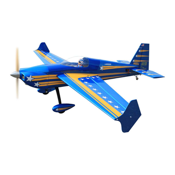
Code : SEA403
ASSEMBLY MANUAL
Speciications:
Wingspan------------------------ 193 cm------------------------- 76 inches.
Length---------------------------- 172 cm------------------------ 67.7 inches.
Wing area------------------------ 70.5 sq.dm------------------- 1093.1 sq.in.
Weight---------------------------- 5.9 kg-------------------------- 13 lbs.
Engine---------------------------- 35 - 40cc.
Radio----------------------------- 6 channels 6 servos.
Motor 180; 3000-3500watt; ESC 80A-120A; Lipo 12s 3300-4200mAh.
Propeller---------------------- 20x8 - 21x10.
1
Advertisement

Related Manuals for Seagull Models Laser 200 16" wingspan ARF 35-40cc


Summary of Contents for Seagull Models Laser 200 16" wingspan ARF 35-40cc
- Page 1 Code : SEA403 ASSEMBLY MANUAL Speciications: Wingspan------------------------ 193 cm------------------------- 76 inches. Length---------------------------- 172 cm------------------------ 67.7 inches. Wing area------------------------ 70.5 sq.dm------------------- 1093.1 sq.in. Weight---------------------------- 5.9 kg-------------------------- 13 lbs. Engine---------------------------- 35 - 40cc. Radio----------------------------- 6 channels 6 servos. Motor 180; 3000-3500watt; ESC 80A-120A; Lipo 12s 3300-4200mAh. Propeller---------------------- 20x8 - 21x10.
- Page 2 Laser 200 76” wingspan ARF 35-40cc (3D/ Aerobatics) Instruction Manual. INTRODUCTION hank you for choosing the Laser 200 76” wingspan ARF 35-40cc (3D/ Aerobatics) ARTF by SG MODELS. he Laser 200 76” wingspan ARF 35-40cc (3D/ Aerobatics) was designed with the intermediate/advanced sport lyer in mind. It is a semi scale airplane which is easy to ly and quick to assemble.
- Page 3 HINGING THE AILERON KIT CONTENTS SEA403 Laser 200 76” wingspan ARF Note : he control surfaces, including the ailer- 35-40cc (3D/ Aerobatics) ons, elevators, and rudder, are prehinged with hinges installed, but the hinges are not glued in 1. Fuselage place.
- Page 4 Laser 200 76” wingspan ARF 35-40cc (3D/ Aerobatics) Instruction Manual. Mix a sufficient amount of 30-min- ute epoxy in a cup, and with a tooth- pick, smear epoxy in the hinge pockets of the wing panel and aileron. Slowly and carefully, insert each hinge into the wing panel.
- Page 5 Note : Work the aileron up and down sev eral times to “work in” the hinges and check for proper movement. Epoxy INSTALL THE AILERONS CONTROL HORN Fiberglass control horn Prepare the aileron control horns by sand- ing the section that extends into the control surface with medium grit sand paper.
- Page 6 Laser 200 76” wingspan ARF 35-40cc (3D/ Aerobatics) Instruction Manual. NOTE : servos arm for aileron is not provided from manufacturer. Layout the servo on the wing to test fit the installation and ensure servo lead is he correct length. Attach the extension to the servo lead and secure with Safety Clip, safety wire, tape or other method.
- Page 7 38mm Install servo with servo mounting screws. hin CA INSTALLING THE AILERON PUSHROD Please study images below. 95mm...
- Page 8 Laser 200 76” wingspan ARF 35-40cc (3D/ Aerobatics) Instruction Manual. INSTALL HINGE FOR STABILIZER AND ELEVATOR Please study images below. Epoxy Repeat all the above steps for the other wing. Epoxy...
- Page 9 INSTALL ELEVATOR CONTROL HORN Epoxy Fiberglass control horn...
- Page 10 Laser 200 76” wingspan ARF 35-40cc (3D/ Aerobatics) Instruction Manual. Epoxy You cut horizontal tail sevor hole. Epoxy Epoxy...
- Page 11 Maximum Servo spec. Torque : 126.6 oz-in (9.11 kg-cm) @ 6.0V; 178 oz-in (12.82 kg-cm) @ 7.4V; 248 oz- in (17.86 kg-cm) @ 8.4V INSTALL HINGE FOR RUDDER AND Please study images below. Epoxy...
- Page 12 Laser 200 76” wingspan ARF 35-40cc (3D/ Aerobatics) Instruction Manual. INSTALL RUDDER CONTROL HORN Epoxy 10mm...
- Page 13 HORIZONTAL TAIL INSTALLATION Please study images below.
- Page 14 Laser 200 76” wingspan ARF 35-40cc (3D/ Aerobatics) Instruction Manual. M3x15mm ELEVATOR PUSHROD INSTALLATION INSTALL RUDDER CABLE AND SERVO Please study images below. NOTE : servos arm is not provided from manufacturer. 150mm Tape the rudder balance tab to the top leading edge of the vertical in in the neutral position as shown.
- Page 15 hread the rudder cable through a brass swage tube, then the threaded co pler, and back through the brass swage tube on both sides. Pull light tension on the cable through the coupler on both sides as shown. Loop the cable back through the brass swage tube and tighten the second loop through the brass swage tube as shown.
- Page 16 Laser 200 76” wingspan ARF 35-40cc (3D/ Aerobatics) Instruction Manual. Crimp the brass tube with a crimping tool or pliers. Cut of excess cable as shown.
- Page 17 Loop the cable back through the brass swage tube and pull tight. Feed one rudder cable through the pre installed cable exit tube in the rear of the fuse toward the front of the fuse. Repeat for other side. Crimp the brass swage tube with a crimping tool or pliers.
- Page 18 Laser 200 76” wingspan ARF 35-40cc (3D/ Aerobatics) Instruction Manual. TAILWHEEL INSTALLATION Locate items necessary to install tailwheel. C/A glue...
- Page 19 M3x15mm M3x15mm...
- Page 20 Laser 200 76” wingspan ARF 35-40cc (3D/ Aerobatics) Instruction Manual. INSTALLING THE MAIN LANDING GEAR TO FUSELAGE Please study images below.
- Page 21 M3x4mm M3x4mm...
- Page 22 Laser 200 76” wingspan ARF 35-40cc (3D/ Aerobatics) Instruction Manual. 3x10mm Loctite 4x20mm M3x10mm...
- Page 23 INSTALLING THE RECEIVER SWITCH Install the switch into the precut hole in the Loctite side, in the fuselage. Trim and cut M4x20mm Switch INSTALLING THE ENGINE SWITCH Trim and cut...
- Page 24 Laser 200 76” wingspan ARF 35-40cc (3D/ Aerobatics) Instruction Manual. Switch FUEL TANK ASSEMBLY Please study images below. MOUNTING THE ENGINE...
- Page 25 Attach throttle pushrod to the carburetor throttle arm with the ball link. 160mm Install adjustable servo connector in the servo arm as same as picture below. Reinstall the servo horn by sliding the connector over the pushrod wire. Center the throttle stick and trim and install the servo horn perpendicular to the servo center line.
- Page 26 Laser 200 76” wingspan ARF 35-40cc (3D/ Aerobatics) Instruction Manual. Connect ignition module to pickup line of Move the throttle stick to the closed posi- engine. Secure with Safety Clip, safety wire, tion and move the carburetor to closed. Use tape or other method.
- Page 27 Tape the cowl to the fuselage using low-tack tape. COWLING Please study images below.
- Page 28 Laser 200 76” wingspan ARF 35-40cc (3D/ Aerobatics) Instruction Manual. Use a drill and drill bit to drill the holes for the cowl mounting screws. Make sure the cowl position is correct before drilling each hole. Install the muler and muler extension onto the engine and make the cutout in the cowl for muler clearance.
- Page 29 ELECTRIC POWER CONVERSION Locate the items neccessary to install the electric power conversion included with your model. Recommend the items necessary to install the electric power conversion parts included with your model. - Motor: 180; 3000 - 3500watt - Propeller: 20x8 - 21x10 - ESC: 80 - 120A - Lipo 12s 3300 - 4200mAh...
- Page 30 Laser 200 76” wingspan ARF 35-40cc (3D/ Aerobatics) Instruction Manual. Attach the electric motor box to the ire- wall centered with the cross lines drawn on the electric motor box and irewall. Using M5x35mm to secure the motor box to the irewall. Please see pictures below. hen, use 5mm drill bit to enlarge the holes on the electric motor box.
- Page 31 Attach the motor mount to the front of the electric motor box using four 6.5mm blind nut, four M5x25mm hex head bolts to secure the motor. Please see picture shown. M5x25mm 160mm Battery Attach the speed control to the side of the motor box using two-sided tape and tie wraps.
- Page 32 Laser 200 76” wingspan ARF 35-40cc (3D/ Aerobatics) Instruction Manual. INSTALLING THE SPINNER Install the spinner backplate, propeller and spinner cone. he propeller should not touch any part of the spinner cone. If it does, use a sharp modeling knife and carefully trim away the spinner cone where the propel- Epoxy ler comes in contact with it.
- Page 33 ATTACHMENT WING - FUSELAGE Attach the aluminium tube into fuselage. Epoxy Wing tube INSTALLING THE BATTERY-RECEVER Plug the servos leads and the switch lead into the receiver. Plug the battery pack lead into the switch also. Wrap the receiver and battery pack in the protective foam rubber to protect them from vibration.
- Page 34 Laser 200 76” wingspan ARF 35-40cc (3D/ Aerobatics) Instruction Manual. INSTALL WING TIP Please study images below. Nylon 4x25mm APPLY THE DECALS If all the decals are precut and ready to stick. Please be certain the model is clean and free from oily ingerprints and dust.
- Page 35 2) he recommended Center of Gravity CONTROL THROWS (CG) location for your model is (153mm) back from the leading edge at the center of the wing. Ailerons: Rudder: High Rate : High Rate : 3) When balancing your model, make Up : 90mm Right : 140mm sure it is assembled and ready for light.
- Page 36 Laser 200 76” wingspan ARF 35-40cc (3D/ Aerobatics) Instruction Manual. 60-120mm 60-120mm 70-140mm Fuselage 70-140mm 50-90mm Wing 50-90mm...
- Page 37 FLIGHT PREPARATION PREFLIGHT CHECK Check the operation and direction of the 1) Completely charge your transmit- elevator, rudder, ailerons and throttle. ter and receiver batteries before your irst day of lying. A) Plug in your radio system per the 2) Check every bolt and every glue manufacturer’s instructions and turn eve- joint in the Laser 200 76”...
- Page 38 Laser 200 76” wingspan ARF 35-40cc (3D/ Aerobatics) Instruction Manual. If you have any queries, or are interested in our products, please feel free to contact us Factory : 12/101A - Hamlet 4 - Le Van Khuong Street - Dong hanh Ward - Hoc Mon District - Ho Chi Minh City - Viet Nam.
Need help?
Do you have a question about the Laser 200 16" wingspan ARF 35-40cc and is the answer not in the manual?
Questions and answers