Table of Contents
Advertisement
"Graphics and specfications may change without notice".
Item code : SEA 68.
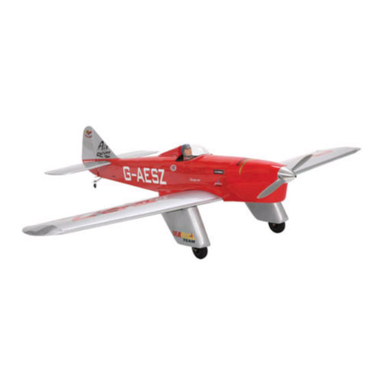
Specifications
Wingspan--------------------------------------85.4 in------------------------------ 216cm.
Wing area------------------------------------ 1371 sq.in-------------------- 88.5 sq.dm.
Approximate flying weight---------------- 19 lbs--------------------------------- 8.6kg.
Length----------------------------------- ------ 71.5in------------------------------- 181cm.
Recommended engine size-------------------------------- 62cc Gasoline Engine.
Radio System required 4 channels with 6 digital servos/karbonite or metal
gear.
Flying skill level Intermediate/advanced.
Kit features.
•
Ready-made—minimal assembly & finishing required.
•
Ready-covered covering.
•
Photo-illustrated step-by-step Assembly Manual.
Made in Vietnam.
ASSEMBLY MANUAL
MS: SEA 68
Advertisement
Table of Contents

Related Manuals for Seagull Models SPARROW HAWK 62 CC


Summary of Contents for Seagull Models SPARROW HAWK 62 CC
- Page 1 MS: SEA 68 ASSEMBLY MANUAL “Graphics and specfications may change without notice”. Item code : SEA 68. Specifications Wingspan--------------------------------------85.4 in------------------------------ 216cm. Wing area------------------------------------ 1371 sq.in-------------------- 88.5 sq.dm. Approximate flying weight---------------- 19 lbs--------------------------------- 8.6kg. Length----------------------------------- ------ 71.5in------------------------------- 181cm. Recommended engine size-------------------------------- 62cc Gasoline Engine. Radio System required 4 channels with 6 digital servos/karbonite or metal gear.
-
Page 2: Fuselage Assembly
Instruction Manual INTRODUCTION. Thank you for choosing the SPARROW HAWK ARTF by SEAGULL MODELS. The SPARROW HAWK was designed with the intermediate/advanced sport flyer in mind. It is a scale airplane which is easy to fly and quick to assemble. The airframe is conventionally built using balsa, plywood to make it stronger than the average ARTF , yet the design allows the aeroplane to be kept light. -
Page 3: Hinging The Ailerons
www.seagullmodels.com NOTE: To avoid scratching your new aero- plane we suggest that you cover your workbench with an old towel. Keep a couple of jars or bowls handy to hold T-pins the small parts after you open the bags. Please trial fit all parts. Make sure you have the correct parts and that they fit and are aligned properly before gluing! This will ensure proper as-... -
Page 4: Installing The Aileron Servos
SPARROW HAWK Instruction Manual 5) Turn the wing panel over and deflect the aileron in the opposite direction from the opposite side. Apply thin C/A glue to each hinge, making sure that the C/A penetrates into both the aileron and wing panel. 6) Using C/A remover/debonder and a paper towel, remove any excess C/A glue that may have accumulated on the wing or in the... -
Page 5: Aileron Control Horn Installation
www.seagullmodels.com Secure the servos with the screws pro- vided with your radio system. String. Electric wire. Plastic Tape. Attach the string to the servo lead and carefully thread it though the wing. Once you have string the lead throught the wing, remove the string so it can use for the other servo lead. -
Page 6: Aileron Pushrod Installation
SPARROW HAWK Instruction Manual Pre-drill at factory. 3.2 mm. M lock nut. Wing bottom. M nut. control horn. Aluminium washer. Loctite secure. Aileron control horn. Repeat the procedure for other aileron. AILERON PUSHROD INSTALLATION. INSTALLING THE MAIN GEAR WIRES. Aileron pushrods assembly follow pictures below. - Page 7 www.seagullmodels.com Support mounting block. 1) Using a modeling knife, remove the covering from over the two main gear mount- Machine screw 3 x 15 mm. ing slots located in the bottom of the wing. 2) Insert the 90º bend of one main gear wire into the predrilled hole in one mounting slot.
-
Page 8: Wing Assembly
SPARROW HAWK Instruction Manual Machine screw 3 x 10 mm. glue. Machine screw 3 x 15 mm. Epoxy glue. Be careful do not to drill through the top of the wing! glue. Reinstall the gear wire and install the four 3 x 15mm wood screws. -
Page 9: Engine Installation
www.seagullmodels.com 3) Peel off the backing from the self adhe- sive covering strip. Apply the strip to the centre section of the wing starting from the bottom trailing edge. Wrap the strip all the way around the wing until it meets the trailing edge again. Trim off any excess strip. -
Page 10: Installing The Stopper Assembly
SPARROW HAWK Instruction Manual INSTALLING THE STOPPER ASSEMBLY. 1) Using a modeling knife, carefully cut off the rear portion of one of the 3 nylon tubes leaving 1/2” protruding from the rear of the stopper. This will be the fuel pick up tube. 2) Using a modeling knife, cut one length of fuel line. -
Page 11: Cowling Installation
www.seagullmodels.com Carefully use a lighter or heat gun to Fuel tank possition. permenently set the angle of the vent tube. Important: When the stopper assembly is in- stalled in the tank, the top of the vent tube should rest just below the top surface of the tank. - Page 12 SPARROW HAWK Instruction Manual 2) While keeping the back edge of the cowl flush with the marks, align the front of the cowl with the crankshaft of the engine. The front of the cowl should be positioned so the crankshaft is in nearly the middle of the cowl Type A.
-
Page 13: Installing The Switch
www.seagullmodels.com Type B2. Elevators Servos. Rudder Servo. Throttle Servo. Type B3. Machine screw 3 x 15 mm. INSTALLING THE SWITCH. Install the switch into the precut hole in the side of the fuselage. 3) Install the muffler and muffler extension onto the engine and make the cut out in the cowl for muffler clearance. - Page 14 SPARROW HAWK Instruction Manual 2) Sand the aluminium tube using sandpaper. This will improve the bond of the epoxy to the cardboard horizontal fin. Coat both sides of one half of the aluminium tube with 30 minute epoxy. Next, pour some epoxy into the cardboard horizontal fin.
-
Page 15: Rudder Control Horn Installation
www.seagullmodels.com 128mm. 162mm. RUDDER CONTROL HORN INSTALLATION. Rudder control horn: Using the same tectniques used aileron control horn. See picture below. 4x15mm. 3x30mm. Rudder control horn. INSTALLATION FIN SET 2. Insert the aluminium tube to fuselage. ELEVATOR PUSHROD INSTALLATION. 162mm. Elevator pushrods assembly follow pictures 128mm. -
Page 16: Mounting The Tail Wheel
SPARROW HAWK Instruction Manual Pushrod L= 114mm. M lock Metal Levis. With the radio on, check the operation of the Center the servo using the radio system. rudder. Adjust the cables so when the rudder servo is centered, the rudder is centered as well. - Page 17 www.seagullmodels.com 2) Wrap the receiver and battery pack in M3 x10 mm. the protective foam rubber to protect them from vibration. 3) Route the antenna in the antenna tube inside the fuselage and secure it to the bot- tom of fuselage using a plastic tape. See pic- 3x25mm.
-
Page 18: Control Throws
SPARROW HAWK Instruction Manual To correct this, move the battery and receiver Silicon glue. 10 mm. forward or if this is not possible, stick weight onto the firewall or use a brass heavy hub spin- ner hub. When balanced correctly, the airplane should sit level or slightly nose down when you lift it up with your fingers. -
Page 19: Preflight Check
www.seagullmodels.com B) Plug in your radio system per the PREFLIGHT CHECK. manufacturer's instructions and turn every- 1) Completely charge your transmitter thing on. and receiver batteries before your first day of flying. C) Check the elevator first. Pull back on 2) Check every bolt and every glue joint the elevator stick. - Page 20 SPARROW HAWK Instruction Manual (c) Purchaser Remedy- Horizon’s sole obligation hereunder shall be that Horizon will, at its option, (i) repair or (ii) replace, any Product determined by Horizon to be defective. In the event of a defect, these are the Purchaser’s exclusive remedies.
Need help?
Do you have a question about the SPARROW HAWK 62 CC and is the answer not in the manual?
Questions and answers