Table of Contents
Advertisement
Quick Links
MS:180
ASSEMBLY MANUAL
"Graphics and specifications may change without notice".
Specifications:
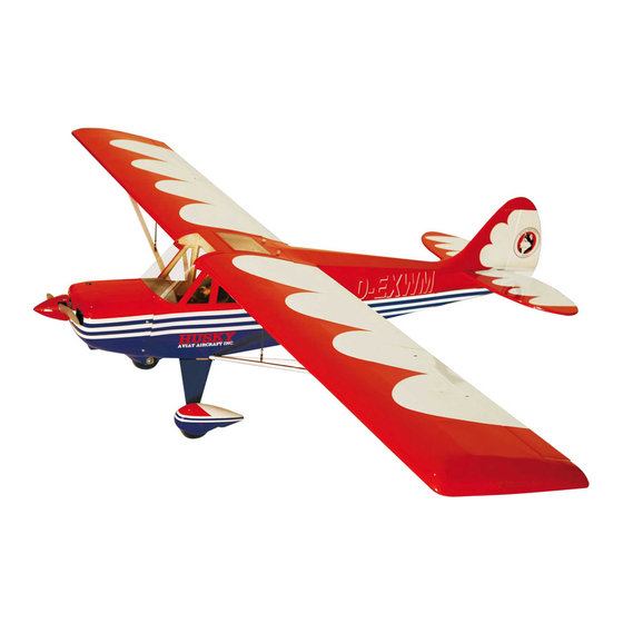
Wing span ------------------------------79.9in (203cm).
Wing area -----------------922.3sq.in (59.5sq dm).
Weight ------------------------7.9-8.8lbs (3.6-4.0kg).
Length ------------------------------50.0in (127.0cm).
Engine ------------------ 0.61-0.75cu.in -----2-stroke.
0.91.in -----4-stroke.
Radio ------------------- 5 channels with 7 servos.
Electric conversion: optional
Advertisement
Table of Contents

Subscribe to Our Youtube Channel
Related Manuals for Seagull Models Husky


Summary of Contents for Seagull Models Husky
- Page 1 MS:180 ASSEMBLY MANUAL “Graphics and specifications may change without notice”. Specifications: Wing span ------------------------------79.9in (203cm). Wing area -----------------922.3sq.in (59.5sq dm). Weight ------------------------7.9-8.8lbs (3.6-4.0kg). Length ------------------------------50.0in (127.0cm). Engine ------------------ 0.61-0.75cu.in -----2-stroke. 0.91.in -----4-stroke. Radio ------------------- 5 channels with 7 servos. Electric conversion: optional...
-
Page 2: Kit Contents
You will find that most of the work has been done for you already.The motor mount has been fitted and the hinges are pre-installed . Flying the CHRISTEN HUSKY is simply a joy. This instruction manual is designed to help you build a great flying aeroplane. Please read this manual thoroughly before starting assembly of your CHRISTEN HUSKY . -
Page 3: Additional Items Required
Decal Set SEA18009 Linkage Set SEA18010 Wing Tube SEA18011 Fiberglass Wheel pants ZZBSEA180B Replacement Box FL180 Floating set for Christen Husky ADDITIONAL ITEMS REQUIRED. 0.61- 0.75 2-stroke. M2x10mm. 0.91 4-stroke. Computer radio with 7 servos. Glow plug to suit engine. -
Page 4: Hinging The Elevators
Instruction Manual. CHRISTEN HUSKY 3) Remove each hinge from the horizontal stabilizer panel and elevator and place a T- pin in the center of each hunge. Slide each hinge into the elevator until the T-pin is snug against the elevator. This will help ensure an... -
Page 5: Hinging The Rudder
www.seagullmodels.com HINGING THE RUDDER Glue the rudder hinges in place using the same techniques used to hinge the ailerons. Epoxy INSTALL THE . INSTALL THE AILERONS CONTROL Fiberglass HORN. Fiberglass control horn. Epoxy Epoxy... - Page 6 Instruction Manual. CHRISTEN HUSKY INSTALL ELEVATOR CONTROL HORN. Aileron control horn. Epoxy Fiberglass control horn. INSTALL FLAP CONTROL HORN. Install the flap control horn using the same method as same as the aileron control horns. Fiberglass control horn. Epoxy Flap control horn.
- Page 7 www.seagullmodels.com wheel collar. Axle. Washer. wheel. Epoxy. wheel. wheel collar. Washer. nut. Axle. wheel Pant. Epoxy C/A glue. Rudder control horn. WHEEL AND WHEEL PANTS. INSTALLING THE MAIN LANDING GEAR TO FUSELAGE. 1)Assembling and muonting the wheel pants as shown below pictures. Axle M4x20mm Wheel collar.
-
Page 8: Engine Mount Installation
Instruction Manual. CHRISTEN HUSKY Thread locker glue M4x20mm Locker glue. M4x20mm ENGINE MOUNT INSTALLATION. M4x20mm 1) Locate the items necessary to install the engine mount included with your model. . 4x30mm. 2) Use four 4x30mm head bolts and four 4mm... -
Page 9: Installing The Stopper Assembly
www.seagullmodels.com Vent tube. Fuel pick up tube. INSTALLING THE STOPPER ASSEMBLY. Fuel fill tube. 1) Using a modeling knife, carefully cut 3) Carefully bend the second nylon tube off the rear portion of one of the 3 nylon tubes up at a 45º angle. This tube is the vent tube. leaving 1/2”... -
Page 10: Installing The Fuselage Servos
Instruction Manual. CHRISTEN HUSKY Vent tube. Fuel pick up tube. C/A glue. Fuel fill tube. 9) Connect the lines from the tank to the engine and muffler. The vent line will connect to the muffler and the line from the clunk to the 7) Slide the fuel tank into the fuselage. -
Page 11: Installing The Switch
www.seagullmodels.com INSTALLING THE SWITCH. Install the switch into the precut hole in the Throttle servo. side, in the fuselage. 3/ 32” Hole. Recomend mounting switch inside fuselage if THROTTLE SERVO ARM INSTALLATION. using floats. Install adjustable servo connector in the servo arm as same as picture below: Loctite secure. - Page 12 Instruction Manual. CHRISTEN HUSKY 4) On the fire wall has the location for the throttle pusshrod tube (pre-drill). 145mm. Pushrod tube hole. 2) Use a pin drill and 4mm drill bit to drill a small indentation in the mount for the engine mounting screw.
- Page 13 www.seagullmodels.com 9) Move the throttle stick to the closed position and move the carburetor to closed. Use a 2.5mm hex wrench to tighten the screw that secures the throttle pushrod wire. Make sure to use threadlock on the screw so it does not vibrate loose.
- Page 14 Instruction Manual. CHRISTEN HUSKY - Model size: .75-.90 size models - Motor: 50mm 310 rev per volt - Propeller: 14x10 ~ 15x10 - ESC: 60A - Lipo Batteries: 8 cell 3200mA 2) Attach the electric motor box to the firewall suitable with the cross lines drawn on the electric motor box and firewall.
- Page 15 www.seagullmodels.com Epoxy. 145mm. Balsa stick. 4mm. Epoxy. Electric motor. 4) Locate the plywood battery tray to the fuselage. Tighten the screws using machine screws M3x15mm to secure the tray in position. Blind nut. Battery. Tie wraps. M3x15mm.
-
Page 16: Installing The Aileron - Flap Servos
Instruction Manual. CHRISTEN HUSKY 5) Attach the speed control to the side of the INSTALLING THE AILERON - FLAP SERVOS. motor box using two-sided tape and tie wraps. Connect the appropriate leads from the speed control to the motor. Make sure the leads will not interfere with the operation of the motor. - Page 17 www.seagullmodels.com C/A glue. 4) Apply 2-3 drops of thin C/A to each of the mounting holes. Allow the C/A to cure without 8) A string has been provided in the wing to using accelerator. pull the aileron lead through to the wing root. Remove the string from the wing at the servo location and use the tape to attach it to the servo extension lead.
- Page 18 Instruction Manual. CHRISTEN HUSKY...
- Page 19 www.seagullmodels.com Wing. M2 lock nut. Aileron. 9) Set the aileron hatch in place and use a Phillips screw driver to install it with four wood INSTALLING THE FLAP SERVO screws. Repeat the procedure for the aileron servo. 50 mm M2 clevis. M2 lock nut.
-
Page 20: Installing The Horizontal Stabilizer
Instruction Manual. CHRISTEN HUSKY 4) With the stabilizer held firmly in place, INSTALLING THE HORIZONTAL STABILIZER. use a pen and draw lines onto the stabilizer where it and the fuselage sides meet. Do this 1) Using a ruler and a pen, locate the... - Page 21 www.seagullmodels.com 7) When you are sure that everything is aligned correctly, mix up a generous amount Remove covering. of 30 Minute Epoxy. Apply a thin layer to the top and bottom of the stabilizer mounting area and to the stabilizer mounting platform sides in the fuselage.
-
Page 22: Horn Installation
Instruction Manual. CHRISTEN HUSKY Rudder control horn. Epoxy. 4) When you are sure that everything is aligned correctly, mix up a generous amount of Flash 30 Minute Epoxy. Apply a thin layer to the M2 clevis. M2 lock nut. mounting slot and to bottom of the vertical sta- bilizer mounting area. - Page 23 www.seagullmodels.com INSTALLATION TAILWHEEL. 1) Locate the items for this section of the manual.
- Page 24 Instruction Manual. CHRISTEN HUSKY 3x25 mm. Aluminum tail landing gear. 2) A scale pilot is included with this ARF. The Seagull Pilot included fitting well to the cockpit. (or you can order others scale pilot figures 3 x 20mm. made by Seagull factory. They are available at Seagull distributors.)
-
Page 25: Apply The Decals
www.seagullmodels.com Receiver. Epoxy Battery. APPLY THE DECALS. ATTACHMENT WING- FUSELAGE. Attach the aluminium tube into fuselage. 1) If all the decals are precut and ready to stick. Please be certain the model is clean and free from oily fingerprints and dust. Position decal on the model where desired, using the Wing tube. - Page 26 Instruction Manual. CHRISTEN HUSKY Epoxy. M3x15mm. Screw. M4x20mm. M3x15mm. M4x12mm. Screw. INSTALLATION STRUT WING-FUSELAGE.
- Page 27 OPTIONAL FLOAT FOR HUSKY. Install Structs onto floats Screw. M3x15mm. 4 x 20 mm 4 x20mm...
- Page 28 Instruction Manual. CHRISTEN HUSKY Screw 3 x 10mm...
- Page 29 www.seagullmodels.com M2 clevis. M2 lock nut. 600mm.
- Page 30 Instruction Manual. CHRISTEN HUSKY C/A glue 4 x 20mm BALANCING. 1) It is critical that your airplane be balanced correctly. Improper balance will cause your plane to lose control and crash. THE CENTER OF GRAVITY IS LOCATED 60 MM BACK FROM THE LEADING EDGE OF THE WING AT THE WING ROOT.
-
Page 31: Control Throws
www.seagullmodels.com With the wing attached to the fuselage, all 3) With the model upright, place your parts of the model installed ( ready to fly), and fingers on the masking tape and carefully lift empty fuel tanks, hold the model at the marked the plane. -
Page 32: Flight Preparation
A) Plug in your radio system per the 2) Check every bolt and every glue joint manufacturer's instructions and turn every- in the CHRISTEN HUSKY to ensure that ev- thing on. erything is tight and well bonded. 3) Double check the balance of the air- B) Check the elevator first.
Need help?
Do you have a question about the Husky and is the answer not in the manual?
Questions and answers