Table of Contents
Advertisement
Quick Links
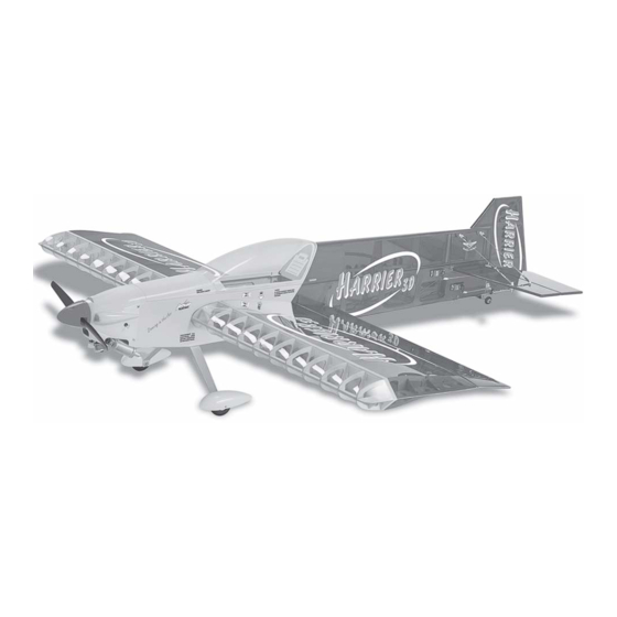
HARRIER 3D
Hand-made Almost Ready to Fly R/C Model Aircraft
Specifications
Wingspan---------------------------------------- 60.5 in---------------------------- 154cm.
Wing area-------------------------------- 948.38 sq.in-------------------- 61.18 sq.dm.
Approximate flying weight--------------------7-8lbs--------------------- 3.17-3.62kg.
Length----------------------------------------------- 66 in------------------------ 167.64cm.
Recommended engine size--------- .61-1.00 cu. in---------------------- 2-stroke.
Radio System required 4 channel with 6 servos.
Flying skill level Intermediate/advanced.
Kit features
•
Ready-made—minimal assembly & finishing required.
•
Ready-covered covering.
•
Factory-installed engine mount.
•
Photo-illustrated step-by-step Assembly Manual.
Made in Vietnam.
ASSEMBLY MANUAL
--------- .91-1.10 cu.in----------------------- 4-stroke.
Advertisement
Table of Contents

Subscribe to Our Youtube Channel
Related Manuals for Seagull Models HARRIER 3D


Summary of Contents for Seagull Models HARRIER 3D
- Page 1 HARRIER 3D Hand-made Almost Ready to Fly R/C Model Aircraft ASSEMBLY MANUAL Specifications Wingspan---------------------------------------- 60.5 in---------------------------- 154cm. Wing area-------------------------------- 948.38 sq.in-------------------- 61.18 sq.dm. Approximate flying weight--------------------7-8lbs--------------------- 3.17-3.62kg. Length----------------------------------------------- 66 in------------------------ 167.64cm. Recommended engine size--------- .61-1.00 cu. in---------------------- 2-stroke. --------- .91-1.10 cu.in----------------------- 4-stroke.
-
Page 2: Fuselage Assembly
Instruction Manual INTRODUCTION Thank you for choosing the Harrier 3D ARTF by SEAGULL MODELS. The Harrier 3D was designed with the intermediate/advanced sport flyer in mind. It is a 3D airplane which is easy to fly and quick to assemble. The airframe is conventionally built using balsa, plywood and veneer to make it stronger than the average ARTF , yet the design allows the aeroplane to be kept light. - Page 3 This will ensure proper as- sembly as the Harrier 3D is made from natural materials and minor ad- justments may have to be made. The paint and plastic parts used in this kit are fuel proof.
-
Page 4: Hinging The Ailerons
HARRIER 3D Instruction Manual 4)Deflect the aileron and completely HINGING THE AILERONS saturate each hinge with thin C/A glue. The ailerons front surface should lightly contact the Note: The control surfaces, including the wing during this procedure. Ideally, when the ailerons, elevators, and rudder, are hinges are glued in place, a 1/64”... -
Page 5: Hinging The Elevators
HARRIER 3D Instruction Manual 7) Repeat this process with the other wing panel, securely hinging the aileron in place. 8) After both ailerons are securely hinged, firmly grasp the wing panel and aileron to make sure the hinges are securely glued and cannot be pulled out. -
Page 6: Installing The Aileron Servos
HARRIER 3D Instruction Manual 6) Using C/A remover/debonder and a paper towel, remove any excess C/A glue that may have accumulated on the horizontal stabilizer or in the elevator hinge area. 7) Repeat this process with the other horizontal stabilizer panel, securely hinging the elevator in place. -
Page 7: Installing The Aileron Linkage
HARRIER 3D Instruction Manual Straight line. 2) Locate the nylon control horns,nylon 1) Install the rubber grommets and brass control horn backplates and two machine collets onto the aileron servo. Test fit the servo screws. into the aileron servo mount. -
Page 8: Installing The Stopper Assembly
HARRIER 3D Instruction Manual FUEL TANK PARTS REQUIRED {1} Molded Nylon Fuel Tank {1} Preassembled Stopper Assembly {1} Metal Weighted Pick-Up {1} Silicon tube INSTALLING THE STOPPER ASSEMBLY 1) Using a modeling knife, carefully cut off the rear portion of one of the 3 nylon tubes leaving 1/2”... - Page 9 HARRIER 3D Instruction Manual Carefully use a lighter or heat gun to You should mark which tube is the vent and permenently set the angle of the vent tube. which is the fuel pickup when you attach fuel Important: When the stopper assembly is in- tubing to the tubes in the stopper.
- Page 10 HARRIER 3D Instruction Manual WHEEL AND WHEEL PANTS 1) Assemble and mounting the wheel pants as shown in the following pictures. (2) Washer. 2) Follow diagram below for wheel pant (2) Wheel Collar. installation: Axle. (2) Washer. Nut. Wheel Collar.
-
Page 11: Installing The Main Landing Gear
HARRIER 3D Instruction Manual INSTALLING THE MAIN LANDING GEAR 1) The blind nuts for securing the landing gear are already mounted inside the fuselage. 2) Using the hardware provided, mount the main landing gear to the fuselage. 5) Attach the Z-Bend in the pushrod wire to the throttle arm on the carburetor. -
Page 12: Installing The Spinner
HARRIER 3D Instruction Manual Hard wood block. Because of the size of the cowl, it may be necessary to use a needle valve ex- tension for the high speed needle valve. Make this out of sufficient length 1.5mm wire and install it into the end of the needle valve. -
Page 13: Elevator - Rudder Servo Installation
HARRIER 3D Instruction Manual THROTTLE SERVO INSTALLTION ELEVATOR - RUDDER SERVO INSTALLATION ) Install adjustable servo connector in the servo arm. Locate and cut out the covering film Adjustable Servo connector. from the servo holes in both sides of fuselage. -
Page 14: Horizontal Stabilizer
HARRIER 3D Instruction Manual 5) Remove the stabilizer. Using the lines HORIZONTAL STABILIZER you just drew as a guide, carefully remove the 1) Using a ruler and a pen, locate the covering from between them using a model- centerline of the horizontal stabilizer, at the trail- ing knife. -
Page 15: Hinging The Rudder
HARRIER 3D Instruction Manual Note: The hinge is constructed of a special HINGING THE RUDDER material that allows the C/A to wick or penetrate and distribute throughout the hinge, securely 1) Carefully remove the rudder from one of bonding it to the wood structure of the fuselage the fuselage panel. - Page 16 HARRIER 3D Instruction Manual Control Horn. Mounting Screws. Mounting Plate. 3) Using a 1.5mm drill bit and the control horns as a guide, drill the mounting holes through the elevator halves. Mount the control horns by inserting the bolts through the control horn bases and elevator halves, then into the mounting backplates.
-
Page 17: Mounting The Tail Wheel Bracket
HARRIER 3D Instruction Manual 5) Slide the clasp back into position and carefully glue it into place using Kwik Bond Thin C/A. Hold the clasp in place until the glue com- pletely cures. Rescue the clap with bolt and nut as picture below. - Page 18 HARRIER 3D Instruction Manual M3 x 3cm. M3 x 4cm. M3 x 4cm. UPPER AND BOTTOM OF M3 x 4cm. HORIZONTAL FIN. M3 x 4cm. M3 x 3cm. CABLE. CABLE LOCK. LOCK CABLE.
- Page 19 HARRIER 3D Instruction Manual UPPER OF FUSELAGE. FUSELAGE BOTTOM. See pictures detail ( pic. 1-2) ATTACHMENT WING-FUSELAGE See pictures below: Picture 1: Picture 1: M3 nut. M3 Clevis. Picture 2: M3 Clevis. M3 nut. LOCK CLEVIS.
-
Page 20: Installing The Switch
HARRIER 3D Instruction Manual 3) Position the battery pack in the fuel tank compartment and the receiver just be- hind the fuel tank . Use extra foam pieces to hold them in position. When balancing the airplane you may need to move the battery or receiver for- ward or after to achieve proper balance. -
Page 21: Flight Preparation
1) We highly recommend setting up the Harrier 3D using the control throws listed at C) Check the elevator first. Pull back on right. We have listed control throws for both the elevator stick. The elevator halves should Low Rate (initial test flying/sport flying) and move up. -
Page 22: Preflight Check
2) Check every bolt and every glue joint in the Harrier 3D to ensure that everything is 8) Properly balance the propeller. An out tight and well bonded. of balance propeller will cause excessive vi-...
Need help?
Do you have a question about the HARRIER 3D and is the answer not in the manual?
Questions and answers