Hitachi DZ-MV350A Service Manual
Hide thumbs
Also See for DZ-MV350A:
- Instruction manual (170 pages) ,
- Mode d'emploi (170 pages) ,
- Instruction manual (170 pages)
Table of Contents
Advertisement
Quick Links
Download this manual
See also:
Instruction Manual
SERVICE MANUAL
MultiMediaCard
TM
SPECIFICATIONS AND PARTS ARE SUBJECT TO CHANGE FOR IMPROVEMENT
DVD VIDEO CAMERA/RECORDER
February
2003
TK
DZ-MV350A
DZ-MV350A(K)
Information of MAN, DRV, SID and HDM
Circuit Boards
During servicing, replace the entire MAN circuit
board, and the entire disc drive unit, including
the DRV, SID and HDM circuit boards.
Because of this servicing method, this service
manual includes only the simplified circuit
board diagrams, and does not include any
schematic circuit diagrams.
The simplified circuit board diagrams show the
major voltage values: Refer to them during
troubleshooting.
Exploded view updated 6/30/03
Digital Media Division,Tokai
No. 7301E
Advertisement
Table of Contents
Troubleshooting

Subscribe to Our Youtube Channel
Related Manuals for Hitachi DZ-MV350A


Summary of Contents for Hitachi DZ-MV350A
- Page 1 No. 7301E DZ-MV350A DZ-MV350A(K) SERVICE MANUAL Information of MAN, DRV, SID and HDM Circuit Boards During servicing, replace the entire MAN circuit board, and the entire disc drive unit, including the DRV, SID and HDM circuit boards. Because of this servicing method, this service...
-
Page 2: Table Of Contents
2-5 List of Functions ........2-7 4-8 Procedure for Removing Disc from 2-6 Compatibility of Recorded Discs ....2-9 Faulty DZ-MV350A ........4-35 2-7 Name of Parts .......... 2-10 4-8-1 Item to be checked ........ 4-35 2-8 Inserting Disc ........... 2-12 4-8-2 How to remove disc ....... - Page 3 (4) Front Block, FAF Circuit Board, and 6-2 Setups for Adjustment ......6-11 R Block ..........5-5 6-2-1 Checking Reference Data ...... 6-11 (5) L Cover, L Case and LCD Block .... 5-6 6-2-2 List of Jigs and Tools for Adjustment ..6-11 (6) Microphone, Microphone Cover, 6-2-3 Test Equipment, Power Supply and Jack Cover, Front Case, and...
- Page 4 Schematic, Circuit Board and Block Diagrams 1 Wiring Diagram ..........1 2 Schematic Diagrams ........2 2-1 FRT Schematic Diagram ......2 2-2 FAF Schematic Diagram ......2 2-3 SAF Schematic Diagram ......2 2-4 GYR Schematic Diagram ......3 2-5 SHE Schematic Diagram ......
-
Page 5: Safety Precaution For Repair
The use of a substitute replacement component which does not have the same safety characteristics as the HITACHI recommended replacement one, shown in the parts list in this Service Manual, may create shock, fire, or other hazards. Product safety is continuously under review and new instructions are issued from time to time. -
Page 6: Notes When Using Service Manual
Safety Precaution for Repair > Notes When Using Service Manual 1-2 Notes When Using Service Manual The following shows the contents to be noted when using service manual: 1-2-1 Value units used in parts list Certain symbols are indicated below for value units of resistors, capacitors and coils in parts list. When you read them note the following regular indications: Parts Indication in list... -
Page 7: Table For Indexing Locations Of Parts
Safety Precaution for Repair > Notes When Using Service Manual 1-2-4 Table for indexing locations of parts This table shows locations of each part on circuit board diagrams. The locations are indicated using the guide scales on the external lines of diagrams. 1) One diagram indicated for each board Symbol Parts... -
Page 8: Electrostatic Protection Measures
Safety Precaution for Repair > Electrostatic Protection Measures 1-3 Electrostatic Protection Measures The laser diode in optical pickup block may be damaged by static electricity charged on clothes, human body, etc. Take great care when handling it to avoid electrostatic damage. 1-3-1 Grounding for prevention of electrostatic damage Perform servicing in an environment where grounding is complete. -
Page 9: Lead-Free Solder
Safety Precaution for Repair > Lead-Free Solder 1-4 Lead-Free Solder To protect the global environment, lead-free solder is used in this product. Be sure to read the following before soldering. Caution Be sure to wear protective goggles so that no solder smoke or scattered solder enters the eye during servicing. -
Page 10: General Description
A 0.44-inch color LCD viewfinder is mounted. A 2.5-inch color LCD monitor is mounted. The volume of DZ-MV350A body has been reduced to half that of DZ-MV230A, by adopting an optical 10-power compact zoom lens and new round DVD holder for disc. -
Page 11: Features
SD memory card and MultiMediaCard (sometimes referred to as “a Round DVD holder card” hereafter). The DZ-MV350A can also copy to a card photos DVD-RAM/ recorded on DVD-RAM disc. DVD-R disc The DZ-MV350A adopts the DCF standard... -
Page 12: Specifications
2-3 Specifications Destinations normally added at the end of model names, (K), etc. are omitted in this table. Specifications are subject to change without notice for the purpose of improvement. Item DZ-MV350A DZ-MV230A 1/4-inch interlaced 1/4-inch interlaced Total number of pixels: Total number of pixels: Approx. - Page 13 ROM, PC connection cable, 8cm DVD- R disc (in round DVD holder) *1: The DZ-MV350A records audio on DVD-R disc using the MPEG Audio layer 2 format in FINE or STD mode, and using the LPCM format in LPCM mode.
- Page 14 General Description > Specifications Specifications of DZ-ACS1/ACS1(K) AC Adapter/Charger (Reference) Power supply 100 - 240 V AC, 50/60 Hz Input capacity 26 VA (at 100 V) DC output (max.) 7.9 V, 1.4 A Charge output 9.4 V, 0.65A Weight 105 g External dimensions (W x H x D) 61 ×...
-
Page 15: Major Differences From Previous Models
Provided DZ-WINPC3 (optional) *1: The DZ-MV350A cannot use the cartridge or caddy which was used on DZ-MV270A, DZ-MV230A, DZ- MV200A and DZ-MV100A. With DZ-MV350A, when using disc that was used on these previous models, remove the disc from cartridge or caddy and place it in round DVD holder. -
Page 16: List Of Functions
General Description > List of Functions 2-5 List of Functions Destinations normally added at the end of model names, (K), etc. are omitted in this table. Item DZ-MV350A DZ-MV230A Switching on-screen language English/French/German/Spanish/ English/French/German/Spanish/ Italian Italian Demonstration mode Auto/Off/Start Auto/Off/Start... -
Page 17: Navigation Function
General Description > List of Functions Item DZ-MV350A DZ-MV230A Jacks Video/audio input/ 10-pin exclusive terminal [S (output Ø 3.5 mm (video/audio L/audio R) × 1 output only)/video/audio L/audio R] × 1 S-Video output Included in Video/audio input/output S-Video output terminal × 1... -
Page 18: Compatibility Of Recorded Discs
DVD-RAM and DVD-R discs recorded or edited on other video camera/recorders can also be recorded, edited or played back on DZ-MV350A: However, a scene memo recorded using the DZ- MV100A Disc Navigation function cannot be played back or edited on DZ-MV350A. -
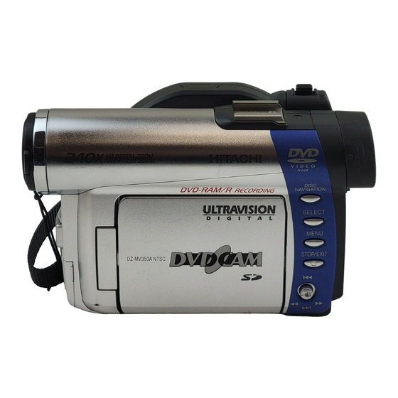
Page 19: Name Of Parts
General Description > Name of Parts 2-7 Name of Parts 1 Recording indicator The red indicator will light during recording. 2 Optical 10× zoom lens 3 Lens hood Always remove this lens hood when using generall y available tele-conversion or wide- conversion lens. - Page 20 General Description > Name of Parts 26 BLC (backlight compensation) button Press this button when subject is being li ghted from rear. 27 DISC NAVIGATION button 28 SELECT button 29 MENU button Press this button to display the menu for setting camera functions and Disc Navigation.
-
Page 21: Inserting Disc
General Description > Inserting Disc 2-8 Inserting Disc (1) Inserting disc to DVD video camera/recorder Pr ess down the DISC EJECT button once and r elease it . DISC EJECT button A few moments after the ACCESS/ PC indicator blinks, the cover of disc insertion block will open slightly. - Page 22 General Description > Inserting Disc (3) Replacing disc in round DVD holder Open SIDE A of the Round DVD Holder, and replace the disc in the holder with the SIDE A mark or label sur face facing up, OPEN marks SIDE A taking care not to touch the disc sur face.
-
Page 23: List Of Abbreviations And Terms For Dvd Video Camera/Recorders
General Description > List of Abbreviations and Terms for DVD Video Camera/Recorders 2-9 List of Abbreviations and Terms for DVD Video Camera/Recorders Index Abbreviation/Term Explanation See Dolby AC3. CPRM Content Protection for Recordable Media: Security technology (cross-certification technology) for SD memory card. Design rule for Camera File system standard: This camera file system standard, established by JEIDA (now merged to JEITA). - Page 24 General Description > List of Abbreviations and Terms for DVD Video Camera/Recorders Index Abbreviation/Term Explanation MPEG Motion Picture Experts Group: Standard related to compression of digital video and audio. MPEG2 is a higher standard of MPEG and is applied to video (movie) requiring higher quality.
-
Page 25: Description Of Operation
(1) Lock mechanism of disc loading block (lock unit) Since the structure of disc loading block in DZ-MV350A is different from that of the lock unit in previous models, it will not open unless a power supply (battery or AC adapter/charger) is connected. - Page 26 Description of Operation > Description of Mechanism (2) Structure schematics 1) Disc cover (includes power switch, speaker and card slot) 2) Lock arm in lock unit 3) DC motor in lock unit 4) Lock unit 5) Disc drive unit 6) Lens cover 7) Hood 8) LCD case U 9) Front cover...
-
Page 27: Description Of Newly Adopted Technology
*2: The copyright protection function conforming to SDMI copyright protection standard is equipped by use of the cross-certification technology (CPRM: Content Protection for Recordable Media). *3: Unusable on the DZ-MV350A, but there is a card (standard) that is referred to as secure MultiMediaCard (SecureMMC) equipped with the copyright protection function. -
Page 28: Standards For Photo Recording On Card
Description of Operation > Description of Newly Adopted Technology 3-2-2 Standards for photo recording on card The DZ-MV350A records photos on SD memory card or MultiMediaCard, conforming to Exif and the DCF standard. The DZ-MV350A also supports DPOF to facilitate printing of photos recorded on SD memory card or MultiMediaCard. -
Page 29: Software Disc-Protect Function
The software disc-protect function is included in the DVD-RAM disc specifications defined by DVD Forum. Therefore, the disc-protect set on DZ-MV350A can be released or set again on devices equipped with the same function. -
Page 30: Troubleshooting
Troubleshooting 4-1 Procedure for Troubleshooting Perform troubleshooting in the order shown in Fig. 4-1-1. Updating No improvement unneeded No message or Check firmware Trouble Check Check Problem guide System reset error code version Diagnosis troubleshooting phenomenon (section 4-3) (section 4-2) appears (section 4-6-1) (section 4-7) -
Page 31: System Resetting/Resetting Camera Functions
Troubleshooting > System Resetting/Resetting Camera Functions 4-2 System Resetting/Resetting Camera Functions The DZ-MV350A has two types of reset function: “System reset” and “Resetting camera functions”. The reset operation will return the various settings to the defaults when the DZ-MV350A was shipped form factory. Information: If a defect occurs in product, take note of settings, and then execute system reset first: The defect may disappear. -
Page 32: System Reset Procedure
1) Connect the battery or AC adapter/charger to power the DZ-MV350A. 2) Set the power switch to “VIDEO” and place the DZ-MV350A in the recording pause status; loading disc is not necessary at this time. For the following steps, operate DZ-MV350A while viewing the LCD monitor or viewfinder. -
Page 33: Problem Guide
Battery weakens fast. Are you using the DZ-MV350A where the temperature is very low? The DZ-MV350A can normally be used for 40 - 60 minutes with a fully charged battery (DZ- BP14S/BP14SW), but this time will be shorter at low temperatures. - Page 34 Playback of image recorded on devices other than DZ-MV350A may be playback. impossible. Has scene been edited on a device other than DZ-MV350A? If a scene that was recorded on DZ-MV350A is edited on a device other than DZ- MV350A, playback may not be possible on DZ-MV350A. 4 - 5...
- Page 35 If the TV has multiple video input jacks, check to see whether the correct input jack was selected. If DZ-MV350A is connected to VCR, set the input selector of VCR to "external input (LINE)". Is DZ-MV350A connected to TV correctly? Check the connections.
- Page 36 The temperature of DZ-MV350A is too high due to continuous operation. to DVD-R disc. Disconnect the DZ-MV350A from PC, remove the disc from DZ-MV350A, set the power switch to "POWER OFF", and then leave it as is until the temperature decreases.
- Page 37 The internal backup battery may be discharged: Charge it. (Charge procedure: Connect the AC adapter/charger to the DZ-MV350A and AC outlet, set the power switch on DZ-MV350A to "POWER OFF", and then leave them for at least 24 hours.) No scene can be deleted.
- Page 38 Point it at the infrared receiver on DZ-MV350A. control. Is the infrared receiver on DZ-MV350A exposed to direct sunlight or strong fluorescent light? The remote control cannot operate DZ-MV350A when strong light strikes the infrared receiver. Adjust the position or angle of DZ-MV350A.
-
Page 39: Messages And Troubleshooting
Create new PlayList. *1: the DVD video recording format defines the maximum number of entry points as 999: Since one entry point is allocated to one scene, the maximum number of scenes recordable on disc with DZ-MV350A is 999. *2: If recording is continued without editing, one scene will comprise one cell for each entry point. - Page 40 CHECK DISC Appears when disc that cannot be used Check the type of disc, and for scratch on the DZ-MV350A, or logically damaged or distortion on disc: If the disc is disc (warped or distorted), was loaded. scratched or distorted, replace it.
- Page 41 If the disc is removed while it is being recognized, the repair function of video file will be invalid. b) If the timing when power is turned off is inappropriate, normal repair may be impossible. c) If the disc has data that was recorded on a device other than DZ-MV350A, normal repair may be impossible.
- Page 42 10. Disc error Appears when the disc has been edited Format the disc (deleting all recorded on a device other than DZ-MV350A, and data), or replace the disc. mismatch has occurred in recorded data. Also appears when reading or writing Clean the disc, or replace it.
- Page 43 Although the choose “YES” and designate it to DZ-MV350A is equipped with a software delete the scenes. disc-protect function that is effective for disc units, it does not comply with software write-protect for program units.
- Page 44 (disc)”. Troubleshooting” for details. *4: The purpose of formatting DVD-R disc on DZ-MV350A is to write to disc a program exclusively for camera recording that is necessary to record images shot by camera in real time (increasing the response from disc).
- Page 45 ERROR ×××× Appears if the self-diagnosis function in Take note of the 4-digit alpha- DZ-MV350A detects a serious problem numerals in ××××, and refer to “4-5 during recording, or when the same Self-Diagnosis Function and trouble occurs three times consecutively Troubelshooting”.
- Page 46 - a photo (conforming to DVD video recording format) file to be displayed on DZ-MV350A, and a photo (JPEG) file for storage that is linked to the photo for display. This message will appear when only the photo file for storage has been deleted on PC, etc.
- Page 47 Appears when a type of disc that cannot Check the type of disc and insert a Please replace disc. be used on DZ-MV350A was loaded. disc usable on DZ-MV350A. This disc is recorded by the Appears when a disc recorded in the PAL Use a disc recorded in the NTSC PAL system.
- Page 48 Set the power switch to “POWER formatted disc has been loaded, OFF” with the disc loaded, and then condensation might have occurred on the leave the DZ-MV350A in a dry place lens or drive of DZ-MV350A. until condensation disappears Condensation will occur when the DZ- (usually 1-2 hours).
-
Page 49: Self-Diagnosis Function And Troubleshooting
The information included in this section is exclusively for service personnel. Do not disclose it to persons other than service engineers. The DZ-MV350A is equipped with a self-diagnosis function: If it detects a problem when power is turned on or during operation, it will display a message, replace the content of problem with an error code (4-digit alphanumeric characters), and then store it in flash memory. - Page 50 Troubleshooting > Self-Diagnosis Function and Troubleshooting (2) Messages for serious problems (Fig. 4-5-3, 4-5-4) These messages appear when solving the problem detected when power is turned on or during operation is not likely by turning power on again or reloading the disc: Error codes (4- Error has occurred.
-
Page 51: Error Codes Stored In Flash Memory
Troubleshooting > Self-Diagnosis Function and Troubleshooting 4-5-2 Error codes stored in flash memory (1) Displaying error codes and clearing them Display method E r r o r c o d e 1) Use the battery or AC adapter/charger to power DZ- MV350A, and then set the power switch to “VIDEO”. -
Page 52: Major Error Codes And Troubleshooting
3) Check to see whether or not condensation has occurred. If condensation has occurred, set the power switch to “POWER OFF” with the disc loaded, and then leave the DZ-MV350A in a dry place for 1-2 hours. 4) Replace the disc. - Page 53 3126 Writing data file to disc failed. power switch to “VIDEO” or “PHOTO” (disc). 3133 Take care not to subject DZ-MV350A to impact or 7601 It takes much more time than vibrations at this time. necessary to process start or end of 2) Set the power switch to “POWER OFF”, remove the...
-
Page 54: Checking Versions Of Firmware And Updating
Display method 1) Connect the battery or AC adapter/charger to power the DZ-MV350A. 2) Set the power switch to “VIDEO” to set DZ-MV350A to the recording pause status. Operate DZ- MV350A while viewing the LCD screen or viewfinder from this point. -
Page 55: Updating Firmware
2) Set the power switch to “POWER OFF”, and then use the AC adapter/charger to power the DZ-MV350A. Do Firmware Update not use a battery: Using battery may interrupt power of DZ-MV350A during work. - Page 56 Troubleshooting > Checking Versions of Firmware and Updating During updating, the screens showing that each Firmware Update firmware program is being updated (Figs. 4-6-3, 4-6-4, 4- 6-5), followed by the screen showing that updating is Updating system. complete (Fig. 4-6-6), will appear. However, not all firmware programs need updating Do not turn off power.
-
Page 57: Trouble Diagnosis
4-7 Trouble Diagnosis 4-7-1 Selecting service position For trouble diagnosis, with a few exceptions it is necessary to disassemble the DZ-MV350A and set it to the service position. There are four types of service position (A)-(D) as shown in the figures below. -
Page 58: Disassembly/Reassembly For Enabling Service Position
Prohibition Disconnect the AC adapter/charger of battery pack from the DZ-MV350A. The DZ-MV350A has a built-in laser emitter block. Do not look into it: If Laser beam strikes your eye, it could cause serious damage. To set to service position (A), (B) or (C), remove the following components, referring to “5. - Page 59 Troubleshooting > Trouble Diagnosis (2) Setting to service position (B) (Fig. 4-7-6) Refer to Table 4-7-1 and the MAN and AEL circuit board diagrams: Solder a lead wire of approx. 10 cm to the check point that corresponds to the symptom (except for terminals of IC or connector/ plug).
- Page 60 Troubleshooting > Trouble Diagnosis AEL CIRCUIT BOARD L BLOCK CIRCUIT BOARD Fig. 4-7-7 Setting to Service Position (C) (4) Setting to service position (D) (Fig. 4-7-8) Remove the following components, referring to “5. Disassembly and Reassembly”: a) Hood, Filter Piece, and Lens Cover (Fig. 5-3-2) b) Eyecup, Accessory Shoe, SAF Circuit Board, and L Block (Figs.
-
Page 61: Trouble Diagnosis Table
2) If there are multiple check points for one symptom, check the items from the top down. Information: Use the DZ-ACS1 adapter/charger to power DZ-MV350A for trouble diagnosis. Prohibition 1) The LCD circuit board has a high-voltage section: When troubleshooting it, take great care to prevent electric shock by wearing gloves, etc. - Page 62 Table 4-7-1 Trouble Diagnosis Tableb (2/3) Service Troubleshooting due to Symptom Check points Detail of check position check results Error message “NO ----- ----- Error message Check connections of DRF DISC” appears even appears approx. 1 circuit board. If no when normal disc is second after disc is abnormality is found,...
- Page 63 Table 4-7-1 Trouble Diagnosis Tableb (3/3) Service Troubleshooting due to Symptom Check points Detail of check position check results Conspicuous block noise ----- ----- ----- Replace MAN circuit during movie recording board. Camera image is TL2084 [MAN-A] Check CCD sensor NG: Replace MAN circuit abnormal TL2085 [MAN-A]...
-
Page 64: Procedure For Removing Disc From Faulty Dz-Mv350A
Prohibition After the above check, disconnect the AC adapter/charger of battery from the DZ-MV350A. The DZ-MV350A has a built-in laser emitter block. Do not look into it: If Laser beam strikes your eye, it could cause serious damage. 4-8-2 How to remove disc If the disc cannot be ejected after performing “4-8-1 Item to be checked”, remove it using the... - Page 65 Troubleshooting > Procedure for Removing Disc from Faulty DZ-MV350A 1) Turn the hood (a) in the direction of the (a) Hood (b) Filter Piece arrow to remove it. (See Fig. 4-8-1) (c) Lens Cover 2) Remove the three screws [A], and then remove the filter piece (b).
-
Page 66: Special Functions
2) Do not turn power off or remove the disc during initialization: Such an interruption will make the disc unusable. 1) Use the AC adapter/charger to power DZ-MV350A, and Disc cleaning method: set the power switch to “VIDEO” or “PHOTO”. -
Page 67: Disassembly And Reassembly
Prohibition After the above check, disconnect the AC adapter/charger of battery pack from the DZ-MV350A. The DZ-MV350A has a built-in laser emitter block. Do not look into it: If Laser beam strikes your eye, it could cause serious damage. (2) Checking Card Make sure that no card is loaded in the card slot. - Page 68 Disassembly and Reassembly > Order of Disassembly Reading Disassembly Flowchart: After locating the target component in the flowchart, remove all components of the target in sequence, following the arrows (routes) from the top of flowchart. If multiple routes exist to the target component from the top of flowchart, remove all the components on all the routes.
-
Page 69: Disassembly
Disassembly and Reassembly > Disassembly 5-3 Disassembly Information: Numbers in figures are step numbers in disassemble procedure, and letters in brackets [ ] show the types of screw. Letters in brackets ( ) show the neme of parts. (a) Adjustment Cover (1) Adjustment Cover (Fig. -
Page 70: Eyecup, Accessory Shoe, Saf Circuit Board, And L Block
Disassembly and Reassembly > Disassembly (3) Eyecup, Accessory Shoe, SAF Circuit Board, and L Block (Figs. 5-3-3, 5-3-4) Eyecup (a) 1) Pull the EVF unit 2) Remove the eyecup in the direction of the arrow. Accessory Shoe (b) 3) Remove three screws [B] and remove the acccessory shoe. SAF Circuit Board (c) and L Block (d) 4) Open the LCD monitor. -
Page 71: Front Block, Faf Circuit Board, And R Block
Disassembly and Reassembly > Disassembly (4) Front Block, FAF Circuit Board, and R Block (Fig. 5-3-5) 1) Open the jack cover (d ), and then remove screw [N] beside the jack. 2) Remove screw [D] from the bottom of front block (a). 3) Remove the front block from R block (c) in the direction of the arrow: Be careful not to damage the FAF circuit board (b) between front block and R block. -
Page 72: L Cover, L Case And Lcd Block
Disassembly and Reassembly > Disassembly (5) L Cover, L Case and LCD Block (Fig. 5-3-6) (a) L Cover L Cover (a) (b) L Case 1 [F] 1) Remove five screws [F] and then remove the (c) LCD Block LCD block and fulcrum block (d) assembled (d) Fulcrum Block with L case from the L cover. -
Page 73: Lcd Case U, Mr Circuit Board, And Fulcrum Block
Disassembly and Reassembly > Disassembly (7) LCD Case U, MR Circuit Board, and Fulcrum Block (Fig. 5-3-8) LCD Case U (a) 1) Insert a fine-tipped screwdriver (e) into the screw hole in fulcrum block, and then turn the screw hole bracket 90° in the direction of the arrow. 2) Turn the fulcrum block 90°... -
Page 74: She, Ael, And Man Circuit Boards
Disassembly and Reassembly > Disassembly (8) SHE, AEL, and MAN Circuit Boards (Fig. 5-3-9) SHE Circuit Board (a) 1) Disconnect the two flat cables from SHE circuit board. 2) Disconnect the flat cable from AEL circuit board in the direction of the arrow. 3) Remove screw [H], and then remove the SHE circuit board from R block (e). -
Page 75: Disc Cover
Disassembly and Reassembly > Disassembly Disc Cover (Figs. 5-3-10, 5-3-11) 1) Move the lock arm (b) in the direction of the arrow to open the disc cover (a). 2) Open the card slot cover (c). 3) Disconnect the flat cable (e) from MAN circuit board (d). 4) Remove four screws [D]. -
Page 76: Evf Unit And Camera Block
Disassembly and Reassembly > Disassembly (10) EVF Unit and Camera Block (Fig. 5-3-12) EVF Unit (a) 1) Disconnect the flat cable from SHE circuit board (c). 2) Remove the screw [A] from the rear of R block (d), and then remove the EVF unit from R block. Note: 1) Take care when handling the EVF unit: The EVF unit contains the LCD panel and backlight, which are precision components. -
Page 77: Usb Circuit Board, Rear Cover, And Hand Strap
Disassembly and Reassembly > Disassembly (11) USB Circuit Board, Rear Cover, and Hand Strap (Fig. 5-3-13) USB Circuit Board (a) 1) Remove screw [D]. 2) Disconnect the flat cable from MAN circuit board (d), and then remove the USB circuit board assembled with USB holder (e) from the R block. -
Page 78: Lcd Circuit Board, Backlight, 2.5 Lcd Unit , And Lcd Case B
Disassembly and Reassembly > Disassembly (12) LCD Circuit Board, Backlight, 2.5 LCD Unit , and LCD Case B (Fig. 5-3-14) LCD Circuit Board (a) 1) Unsolder the two points on LCD circuit board. 2) Disconnect the flat cable from LCD circuit board. 3) Remove screw [H], and then remove the LCD circuit board. -
Page 79: Link Bracket, Drive Block, Top Cover And R Case
Disassembly and Reassembly > Disassembly (13) Link Bracket, Drive Block, Top Cover and R Case (Figs. 5-3-15, 5-3-16, 5-3-17) Link Bracket (a) (Fig. 5-3-15) 1) Remove two screws [J], and then remove the link bracket. Drive Block (b), Top Cover (c) and R Case (d) (Figs. 5-3-15, 5-3-16, 5-3-17) 2) Remove screw [D]. -
Page 80: Fulcrum Cover U And Fulcrum Cover B
Disassembly and Reassembly > Disassembly (14) Fulcrum Cover U and Fulcrum Cover B (Fig. 5-3-18) 1) Remove two screws [D] and then remove the (a) Fulcrum Cover U fulcrum cover U (a) and fulcrum cover B (b). (b) Fulcrum Cover B 1 [D] [D] M1.6×2.5 (Black) Fig. -
Page 81: Loader, Drf Circuit Board, Disc Drive Unit, And Lock Unit
Disassembly and Reassembly > Disassembly (16) Loader, DRF Circuit Board, Disc Drive Unit, and Lock Unit (Fig. 5-3-20) Loader (a) 1) Remove two screws [L], and then remove the loader from disc drive unit. Note: Do not subject the loader to undue force: If the loader is damaged, discs cannot be inserted or recognized. -
Page 82: Adjustment
3) Start up Explorer and open the refdata folder in map03w folder. 4) Copy the file with the same name as the reference data file name checked in step 2) in refdata folder to map03w folder. Model Name of reference data file DZ-MV350A m350a.dat DZ-MV350E m350e.dat DZ-MV380A m380ae.dat... -
Page 83: Reference Data
Adjustment > Creating Reference Data 6-1-1 List of Jigs and Tools used when Creating Reference Data Adjustment floppy disk Skylark connection jig Note: Create the data using the adjustment data Parts No. TP14161 downloaded from Intranet. If downloading is not possible, obtain the floppy disk with Parts No. -
Page 84: Connections When Creating Reference Data
Adjustment > Creating Reference Data 6-1-2 Power Supply and Materials for Creating Reference Data 1) DVD video camera/recorder that is the same model as the one to be adjusted and whose camera block is operating normally. Note: It is recommended that you use a brand-new unit of the same model when creating the reference data. - Page 85 Adjustment > Creating Reference Data LIGHT BOX 30 - 50cm FRONT SECTION REMOVE THE ADJUSTMENT COVER [Refer to "(1) Adjustment To VIDEO IN COLOR cover" in "5-3 Disassembly"] TERMINAL AV/S INPUT/ MONITOR OUTPUT CABLE RESET SKYLARK BUTTON CONNECTION DC POWER To AC CORD AC ADAPTER/...
- Page 86 Adjustment > Creating Reference Data 6-1-4 Settings when Creating Reference Data When the connections for creating reference data are complete, set the DVD video camera/recorder and test equipment as follows: 1) Make sure that no disc or card is inserted: Neither is necessary when creating reference data. 2) Set the power switch to “VIDEO”, and set the DVD video camera/recorder to the recording pause status: After that operate the DVD video camera/recorder while watching the LCD monitor screen.
-
Page 87: Adjustment Program
Adjustment > Creating Reference Data 6-1-5 Storing or Deleting Adjustment Program Information: The adjustment program also includes a program for creating reference data. (1) Storing 1) Start the PC. 2) Start Explorer and create a new folder in HDD of PC. The name “map03w” is recommended for the folder: If a folder with the same name exists, give the folder a similar name that is easily understandable. - Page 88 DVD video camera/recorder or DSP-R jig is powered. 2) If there is a problem in connections or power supply, Copyright (C) HITACHI, Ltd 2003 take care of the problem, and then click the YES button to proceed with the MODEL SELECT screen.
- Page 89 Adjustment > Creating Reference Data 6) Choose the radio button of corresponding model name in MODEL SELECT screen. MODEL SELECT screen. MANUAL ADJUSTMENT PROGRAM for SERVICE STATION 7) Click the ENTER button in MODEL SELECT screen, MODEL SELECT and then proceed with the SETUP MENU screen. ×...
-
Page 90: Creating Reference Data
Adjustment > Creating Reference Data 6-1-7 Creating Reference Data Start the setup program referring to “6-1-6 Starting and Terminating Reference Data Creation Program”. For subsequent operation, operate the PC mouse while watching the PC monitor screen. Information: SETUP MENU screen. It takes approx. - Page 91 Adjustment > Creating Reference Data 8) Check WHITE BALANCE ABS on the SETUP MENU SETUP MENU screen. screen. MANUAL ADJUSTMENT PROGRAM for SERVICE STATION 9) Repeat steps 2)-5). SETUP MENU 10) Click the RETURN button on SETUP MENU screen. Matrix 11) The ALL SETUP FINISH dialog will appear: Click the White Balance OK button to complete the creation of reference data.
-
Page 92: Setups For Adjustment
Adjustment > Setups for Adjustment 6-2 Setups for Adjustment 6-2-1 Checking Reference Data Before starting adjustment, check whether it will be necessary to create the reference data or not, referring to the flowchart below: Have you ever performed adjustment of this model? Does the “map03w”... -
Page 93: Test Equipment, Power Supply And Charts For Adjustment
Adjustment > Setups for Adjustment 6-2-3 Test Equipment, Power Supply and Charts for Adjustment 1) Color bar chart Color Bar Chart 2) 3100 K light box (maintenance is necessary) 3) Backfocus chart 4) Color monitor (color TV with AV input jacks) 5) Oscilloscope 6) Vectorscope 7) Digital voltmeter... - Page 94 Adjustment > Setups for Adjustment LIGHT BOX VECTORSCOPE OUTPUT INPUT 30 - 50cm OSCILLOSCOPE CH1 CH2 TRIG FRONT SECTION REMOVE THE ADJUSTMENT COVER [Refer to "(1) Adjustment cover" in "5-3 Disassembly"] AV/S INPUT/ OUTPUT CABLE RESET SKYLARK BUTTON CONNECTION When using an DC POWER To AC oscilloscope only...
-
Page 95: Settings For Adjustment
Adjustment > Setups for Adjustment 6-2-5 Settings for Adjustment When the connections for adjustment are complete, set the DVD video camera/recorder and test equipment as follows: (1) Setting the DVD video camera/recorder Information: This item is the same as when creating reference data. 1) Make sure that no disc or card is inserted: Neither is necessary for adjustment. - Page 96 Adjustment > Setups for Adjustment (2) Setting test equipment The names of switches, etc. of test equipment may vary depending on the manufacturer and model. Some switches in addition to those shown below may have to be set: See the instruction manual of test equipment for details.
- Page 97 EXIT 5) Click the OK button on the COMMUNICATION PORT SETTING screen, and then proceed with the MODEL SELECT screen. Copyright (C) HITACHI, Ltd 2003 Note: POWER OR CONNECTION ERROR If the POWER OR CONNECTION ERROR dialog appears , dialog...
- Page 98 Adjustment > Setups for Adjustment 6) Choose the radio button of corresponding model name in MODEL SELECT screen. MANUAL ADJUSTMENT PROGRAM for SERVICE STATION MODEL SELECT screen. 7) Click the ENTER button in MODEL SELECT screen, MODEL SELECT and then proceed with the ADJUST MENU screen. ×...
-
Page 99: List Of Adjustment Items
Adjustment > List of Adjustment Items 6-3 List of Adjustment Items 6-3-1 Adjustment Program Hierarchy Diagram Communication Port Setting Model Select MANUAL ADJUSTMENT PROGRAM for SERVICE STATION Data Initialize × × × × MODEL NAME: ADJUST MENU DATA INITIALIZE VIDEO LEVEL Video Level BURST LEVEL SAMPLING PULSE... -
Page 100: Replacing Major Components
6-3-2 List of Adjustments Needed After Replacing Major Components Major Components IC1301 IC1401 IC3701 IC6103 Lens unit Item circuit unit IC1302 IC1402 [For DZ-MV350A/ board unit IC1403 MV350E] Data Initialize Video Level Burst Level Sampling Pulse Autofocus Auto Iris Control Matrix... -
Page 101: Purpose Of Adjustments And Incompleted Phenomenon
Adjustment > List of Adjustment Items 6-3-3 Purpose of Adjustments and Incompleted Phenomenon Item Purpose Incompleted Phenomenon Data Initialize To initialize EEPROM. ------------ Video Level To set the video output level. The picture becomes dark or whitish. Burst Level To set the burst level. Sampling Pulse To measure the delay time in sampling Diagonal beats and horizontal noise occur. -
Page 102: Adjustment Procedure
Adjustment > Adjustment Procedure 6-4 Adjustment Procedure Start the adjustment program referring to “6-2-6 Starting and Terminating Adjustment Program”. For the subsequent operation, operate the PC mouse while watching the PC monitor screen. Information: 1) Display ×××× on subsequent PC screen shows the model name. 2) The numbers on PC screens show the operational procedure. -
Page 103: Video Level
Adjustment > Adjustment Procedure ADJUST MENU screen 6-4-2 Video Level MANUAL ADJUSTMENT PROGRAM for SERVICE STATION ×××× Preparations: MODEL NAME: 1) Connect the oscilloscope CH1 to video out. ADJUST MENU DATA INITIALIZE 2) Switch the oscilloscope V-MODE to “CH1” and VIDEO LEVEL TRIGGER SOURCE to “CH1”. -
Page 104: Burst Level
Adjustment > Adjustment Procedure ADJUST MENU screen 6-4-3 Burst Level MANUAL ADJUSTMENT PROGRAM for SERVICE STATION ×××× Preparations: MODEL NAME: 1) Connect the oscilloscope CH1 to video out. ADJUST MENU DATA INITIALIZE 2) Switch the oscilloscope V-MODE to “CH1” and VIDEO LEVEL TRIGGER SOURCE to “CH1”. -
Page 105: Sampling Pulse
Adjustment > Adjustment Procedure ADJUST MENU screen 6-4-4 Sampling Pulse MANUAL ADJUSTMENT PROGRAM for SERVICE STATION ×××× Note: MODEL NAME: ADJUST MENU Start this adjustment after the circuit operation is DATA INITIALIZE stabilized, e.g., after leaving the DVD video camera/ VIDEO LEVEL recorder for at least one hour at normal temperature, and BURST LEVEL... -
Page 106: Autofocus
Adjustment > Adjustment Procedure ADJUST MENU screen 6-4-5 Autofocus MANUAL ADJUSTMENT PROGRAM for SERVICE STATION Preparations: ×××× MODEL NAME: 1) Set the backfocus chart as shown in Fig. 6-4-3. ADJUST MENU 2) Point at backfocus chart 1500mm ± 5 mm away from the DATA INITIALIZE VIDEO LEVEL lens surface: Measure the distance precisely. -
Page 107: Auto Iris Control
Adjustment > Adjustment Procedure 6-4-6 Auto Iris Control ADJUST MENU screen MANUAL ADJUSTMENT PROGRAM for SERVICE STATION Preparation: ×××× MODEL NAME: Set zoom to wide-angle end, and point at light box without ADJUST MENU chart, filling the screen. DATA INITIALIZE VIDEO LEVEL Procedure: BURST LEVEL... -
Page 108: Matrix
Adjustment > Adjustment Procedure 6-4-7 Matrix ADJUST MENU screen MANUAL ADJUSTMENT PROGRAM for SERVICE STATION Preparation: ×××× MODEL NAME: Point at light box without chart, filling the screen. ADJUST MENU Prepare the C12 light balancing filter (set-up rings): Attach DATA INITIALIZE VIDEO LEVEL it during adjustment. -
Page 109: Chroma Gain
Adjustment > Adjustment Procedure 6-4-8 Chroma Gain Preparation: Point at light box without chart, filling the screen. Prepare the color bar chart: Use it during adjustment. Procedure: 1) Press the MENU button on DVD video camera/recorder, and use the joystick to specify “White Bal.: Set”... - Page 110 B = 780mV ± 20 mVp-p BURST BURST 280% 280% ± 5% ± 5% 100% 100% Fig. 6-4-5 When using a vectorscope Fig. 6-4-6 When using a vectorscope [DZ-MV350A/MV380A] [DZ-MV350E/MV380E] 780mV ± 20mVp-p Fig. 6-4-7 When using an oscilloscope 6 - 29...
-
Page 111: Stabilizer
Adjustment > Adjustment Procedure 6-4-9 Stabilizer Note: Perform STABILIZER only after replacing any component on the GYR circuit board or executing “Data Initialize”. This item STABILIZER is not an adjustment, but is performed to write the camera shake correction value contained in adjustment program to EEPROM. Although the camera shake correction value written to EEPROM is an adjustment value inherent in individual devices when shipped from the factory, the camera shake correction value contained in adjustment program is an average value set at the factory. -
Page 112: Spot Noise
Adjustment > Adjustment Procedure 6-4-10 Spot Noise Information: 1) The SPOT NOISE adjustment compensates for bright points that appear on the screen, and these are caused by a defect in pixel of CCD (image sensor) that may occur when DVD video camera/recorder is used under particular conditions or for a long time. -
Page 113: Lcd
Adjustment > Adjustment Procedure 6-4-11 LCD Note: 1) Perform LCD only after replacing the MAN circuit board or 2.5 LCD Unit, or executing “Data Initialize”. 2) Neither light box nor chart is needed for LCD adjustment. Before performing any adjustments for LCD, be sure to shift the DVD video camera/recorder to the test mode using the procedure below, and then display the LCD ADJUSTMENT MENU. - Page 114 Click the OK button in dialog to DOWN restore the LCD ADJUSTMENT MENU screen. Table 6-4-2 Value of Frequency Model Value SAVE RETURN DZ-MV350A/MV380A 15.734 kHz ± 0.1 kHz DZ-MV350E/MV380E 15.625 kHz ± 0.1 kHz ADJUSTMENT FINISHED dialog FINISHED ADJUSTMENT FINISHED. 6 - 33...
- Page 115 Click the OK button in dialog to restore the LCD ADJUSTMENT MENU screen. Table 6-4-3 Value of Level A SAVE RETURN Model Value DZ-MV350A/MV380A 7.55V ± 0.1V DZ-MV350E/MV380E 8.0V ± 0.1V ADJUSTMENT FINISHED dialog FINISHED ADJUSTMENT FINISHED.
- Page 116 Click the OK button in dialog to restore the LCD ADJUSTMENT MENU screen. Table 6-4-3 Value of Level B SAVE RETURN Model Value DZ-MV350A/MV380A 2.35V ± 0.1V DZ-MV350E/MV380E 2.10V ± 0.1V ADJUSTMENT FINISHED dialog FINISHED ADJUSTMENT FINISHED.
- Page 117 Adjustment > Adjustment Procedure LCD ADJUSTMENT MENU screen (4) LCD White Balance MANUAL ADJUSTMENT PROGRAM for SERVICE STATION Preparations: 1) Connect the oscilloscope CH1 to “LCD-R (pin 3)” of LCD ADJUSTMENT MENU Skylark Connection jig. LCD ADJUSTMENT MENU 2) Connect the oscilloscope CH2 to “LCD-G (pin 5)” of Skylark Connection jig.
- Page 118 Adjustment > Adjustment Procedure 7) Connect the oscilloscope CH1 to “LCD-B (pin 7)” of SUB BRIGHT BLUE ADJUSTMENT screen. Skylark Connection jig. MANUAL ADJUSTMENT PROGRAM for SERVICE STATION 8) Use the same procedure as in step 3) to equalize levels a and b of the waveform.
-
Page 119: Evf
Adjustment > Adjustment Procedure 6-4-12 EVF Note: 1) Perform EVF only after replacing IC3701 and its peripheral components, MAIN circuit board or EVF unit, or executing “DATA Initialize”. 2) Neither light box nor chart is needed for EVF adjustment. Before performing any adjustments for EVF, be sure to shift the DVD video camera/recorder to the test mode using the procedure below, and then display the EVF ADJUSTMENT MENU. - Page 120 Adjustment > Adjustment Procedure (1) BL DET Check Note: Be sure to take note of the resulting value of this check because the check value will be needed when EVF adjustment is completed. There are two types of EVF unit mounted in these DVD video camera/recorder series models: The backlight characteristics of the two types are different.
- Page 121 Adjustment > Adjustment Procedure (3) EVF Brightness EVF ADJUSTMENT MENU screen Preparations: MANUAL ADJUSTMENT PROGRAM for SERVICE STATION 1) Connect the oscilloscope CH1 to video output. EVF ADJUSTMENT MENU 2) Connect the oscilloscope CH2 to “EVF-G (pin 4)” of EVF ADJUSTMENT MENU Skylark Connection jig.
- Page 122 Adjustment > Adjustment Procedure EVF ADJUSTMENT MENU screen (4) EVF Contrast MANUAL ADJUSTMENT PROGRAM for SERVICE STATION Preparations: 1) Connect the oscilloscope CH2 to “EVF-G (pin 4)” of EVF ADJUSTMENT MENU Skylark Connection jig. Confirm the CH1 connection to EVF ADJUSTMENT MENU video out.
- Page 123 Adjustment > Adjustment Procedure EVF ADJUSTMENT MENU screen (5) EVF White Balance MANUAL ADJUSTMENT PROGRAM for SERVICE STATION Preparations: 1) Connect the oscilloscope CH1 to “EVF-R (pin 2)” of EVF ADJUSTMENT MENU Skylark Connection jig. EVF ADJUSTMENT MENU 2) Connect the oscilloscope CH2 to “EVF-G (pin 4)” of Skylark Connection jig.
- Page 124 Adjustment > Adjustment Procedure 7) Connect the oscilloscope CH1 to “EVF-B (pin 6)” of SUB BRIGHT BLUE ADJUSTMENT screen. Skylark Connection jig. MANUAL ADJUSTMENT PROGRAM for SERVICE STATION 8) Use the same procedure as in step 3) to equalize levels a and b of the waveform.
-
Page 125: Exploded View And Parts List
Exploded View and Parts List 7-1 Exploded Views Note: Components without any numbers in exploded views had not been assigned as service parts as of the date of issue 7-1-1 Main Section of this manual. USB CIRCUIT BOARD DVD DRIVE UNIT [Component [Unit Replacement Replacement]... -
Page 126: Lcd Block Section
7-1-2 LCD Block Section MR CIRCUIT BOARD [Component Replacement] LCD CIRCUIT BOARD [Component Replacement] 7 - 2... -
Page 127: Replacement Parts List
7-2 Replacement Parts List 7-2-1 Mechanical Parts List SYMBOL SYMBOL P-NO DESCRIPTION P-NO DESCRIPTION EV11001 CORD,ACINLET [For 350A] MECHANISM SECTION EV10961 CORD,ACINLET [For 350A(K)] EW12432 CORD,AVS JP36072 PWB ASSY MAIN EV11012 CORD,DC UA12391 DVD DRIVE MECHA(PC3A) HL11392 REMOTE HAND SET QX15621 COVER,TOP EW12441... -
Page 128: Electrical Parts List
7-2-2 Electrical Parts List SYMBOL SYMBOL P-NO DESCRIPTION P-NO DESCRIPTION C3725 0893267 CHIP CAPACITOR 22PF +-5% 50V CAMERA & VCR SECTION C3728 AA00952R CHIP CAPACITOR 0.68UF+-10% 16V C3891 AA00951R CERAMIC CAPACITOR 1.0UF+-10% 16V C1301 AA01132R CERAMIC CAPACITOR 0.22UF+-10% 6.3V C3892 0893193 CERAMIC CHIP 0.01UF+-10% 25V C1302... - Page 129 SYMBOL SYMBOL P-NO DESCRIPTION P-NO DESCRIPTION C6331 AA10872R CHIP CAPACITOR 0.1UF+-10% 10V IC3701 CK29701U IC CXA3503R C6332 0893333 CERAMIC CHIP 0.01UF+-10% 16V IC6101 CK22341R IC NJM2112V-TE1 C6333 0893333 CERAMIC CHIP 0.01UF+-10% 16V IC6102 CP12001R IC NJM2904V-TE1 C6334 AA10872R CHIP CAPACITOR 0.1UF+-10% 10V IC6103 CK42511U IC AN2903FJQ-V...
-
Page 130: Wiring Diagram
Schematic, Circuit Board and Block Diagrams 1. WIRING DIAGRAM DISC DRIVE UNIT LENS UNIT PG2302 70PIN CCD/FOCUS MOTOR/ ZOOM MOTOR/IRIS 4PIN PG9501 PG9303 6PIN PG9403 SLID TEST MOTOR PG9701 PG2301 BATTERY TERMINAL SPINDLE 16PIN PG9404 PG9103 70PIN MOTOR 15PIN PG2001 REAR COVER PG9301 DISC DRIVE... -
Page 131: Schematic Diagrams
2. SCHEMATIC DIAGRAMS 2-2 FAF SCHEMATIC DIAGRAM 2-1 FRT SCHEMATIC DIAGRAM CN1801 CODE PART NAME 2SC5385T11 2SD2345-S DTC114YE MA132WA ONE VOLTAGE:PB OR REC MODE TWO VOLTAGES:PB AND (REC) MODE BOARD To BOARD PG1801 [AEL] PG7003 RECEIVER 0(3) 2-3 SAF SCHEMATIC DIAGRAM L CASE BOARD To BOARD (OPERATION SW) -
Page 132: Gyr Schematic Diagram
2-4 GYR SCHEMATIC DIAGRAM 2-5 SHE SCHEMATIC DIAGRAM VL1220/F3A CODE PART NAME XP4501 VOLTAGE: PB OR REC MODE UNIT CN1401 PG0154 0-3.1 0-3.1 1.3 1.3 - 3 -... -
Page 133: Board To Board [Ael] Schematic Diagram
2-6 BOARD To BOARD [AEL] SCHEMATIC DIAGRAM PG3401 LENS DRIVE 1A-21A FOR ADJUSTMENT. BM10696R CN7003 BM10696R AUDIO 1C-42C BM10696R CN7004 BM10696R 3.1(0) DECODER TL7041 CODE PART NAME UMH9N MA133 ONE VOLTAGE:PB OR REC MODE TWO VOLTAGES:PB AND (REC) MODE 15B-27B PG0151 BOARD To BORAD [AEL] PG1501... -
Page 134: Lens Drive [Ael] Schematic Diagram
2-7 LENS DRIVE [AEL] SCHEMATIC DIAGRAM PB: 0 REC: LENS PB: 0 UNIT REC: PB: 0.2 REC: PB: 0 REC: HALL ZOOM MOTOR DRIVE PB: 0 CONT. REC: FOCUS MOTOR EXT2 DRIVE IRIS MOTOR DRIVE 0.4(1.9) PB: 0 REC: AF/ZOOM IRIS PB: 0 IRIS DRIVE... -
Page 135: Audio [Ael] Schematic Diagram
2-8 AUDIO [AEL] SCHEMATIC DIAGRAM REC: 0 2.0 3.9 BE10391R BE10391R R6209 2.3 0 BOARD To BOARD 1C-3C 3.1 3.1 1.4 1.4 1.4 1.4 1.4 1.4 1.4 1.4 1.4 TL6101 TL6102 CODE PART NAME 2SA1774RS 2SD2216 DTC124EE DTC114YE MA132K ONE VOLTAGE:PB OR REC MODE TWO VOLTAGES:PB AND (REC) MODE SP3V (0.5) -
Page 136: Evf [Ael] Schematic Diagram
2-9 EVF [AEL] SCHEMATIC DIAGRAM 12.0 12.0 TL3719 11.0 EVF DRIVER BOARD To BOARD 1B-14B CODE PART NAME 2SA1774RS BOARD To BOARD DTC114YE 15B-27B HVU200A-T VOLTAGE: PB OR REC MODE. EVF [AEL] - 7 -... -
Page 137: Lcd Schematic Diagram
2-10 LCD SCHEMATIC DIAGRAM INVERTER TRANS 15.0 CODE PART NAME 2SA1774RS CAUTION BACK DTC114YE LIGHT RISK OF ELECTRIC SHOCK VOLTAGE: PB OR REC MODE. 15.0 12.0 12.0 CN3401 11.3 12.0 LCD DRIVER 0.1 1.5 1.3 2.1 BOARD To BOARD PG7008 LCD UNIT - 8 -... -
Page 138: Mr Schematic Diagram
2-11 MR SCHEMATIC DIAGRAM 2-13 DRF SCHEMATIC DIAGRAM VOLTAGE: PB OR REC MODE. REVERSE AN48800A CN3401 OPEN/CLOSE AN48800A PG3403 2-12 USB SCHEMATIC DIAGRAM DISC DRIVE UNIT PG2002 (DRV-PG9701) BL8102 PC TERMINAL PG5001 - 9 -... - Page 139 IC3401 2-14 IC BLOCK DIAGRAMS IC3701 CXA3582R CXA3503R EVF DRIVER LCD DRIVER PICTURE Gain PICTURE MODE GND3 +12.0V +12.0V PICTURE PSIG- BRIGHT +3.0V G OUT MATRIX SYNC IN OSD RGB COLOR TST15 G DC DET FILTER CONTRAST USER-BRIGHT DA OUT MUE COLOR CONT U-BRT...
-
Page 140: Circuit Board Diagram
3. CIRCUIT BOARD DIAGRAMS 3-2 FAF, SAF CIRCUIT BOARD DIAGRAMS 3-1 FRT CIRCUIT BOARD DIAGRAM CN1801 CN7003 FAF -SIDE A- [PATTERN No.JD1153-5] JD1153 FRT -SIDE A- FAF -SIDE B- [PATTERN No.JD1153-5] [PATTERN No.JD1153-5] PD1801 CN7004 CN8012 SAF -SIDE A- [PATTERN No.JD1153-5] JD1153 SAF -SIDE B- FRT -SIDE B-... -
Page 141: Gyr Circuit Board Diagram
3-3 GYR CIRCUIT BOARD DIAGRAM 3-4 DRF CIRCUIT BOARD DIAGRAM CN1401 GYR -SIDE A- [PATTERN No.JD1153-5] DRF -SIDE A- DRF -SIDE B- [PATTERN No.JD1153-5] [PATTERN No.JD1153-5] GYR -SIDE B- [PATTERN No.JD1153-5] - 12 -... -
Page 142: She, Mr, Usb Circuit Board Diagrams
3-5 SHE, MR, USB CIRCUIT BOARD DIAGRAMS CN8101 BA1801 USB -SIDE A- [PATTERN No.JD1153-5] MR -SIDE B- [PATTERN No.JD1153-5] SHE -SIDE A- SHE -SIDE B- [PATTERN No.JD1153-5] [PATTERN No.JD1153-5] USB -SIDE B- [PATTERN No.JD1153-5] CN3401 MR -SIDE A- [PATTERN No.JD1153-5] - 13 -... -
Page 143: Ael Circuit Board Diagram
3-6 AEL CIRCUIT BOARD DIAGRAM TL3719 TL7041 TL6102 TL6101 AEL -SIDE A- AEL -SIDE B- [PATTERN No.JA2090-5] [PATTERN No.JA2090-5] - 14 -... -
Page 144: Lcd Circuit Board Diagram
3-7 LCD CIRCUIT BOARD DIAGRAM TL3462 TL3461 BACK LIGHT CAUTION TL3418 RISK OF ELECTRIC SHOCK [PATTERN No.JA2104-4] - 15 -... -
Page 145: Man Circuit Board Diagram
3-8 MAN CIRCUIT BOARD DIAGRAM TL0520 TL0519 TL0502 TL1544 TL2004 TL0521 TL0501 TL0518 TL1543 33(4.8) 38(4.8) 32(4.8) 39(4.8) 31(4.8) 40(4.8) 30(4.8) 41(4.8) 28(2.5) 43(2.5) 26(3.1) 1- 5 (3.1) 25(3.1) (8.0) TL0517 TL1547 F0502 (K:1.5A/32V) F0503 (K:1.5A/32V) (7.8) (7.8) (7.8) F0504 (K:1.5A/32V) F0501 TL0512... -
Page 146: Drv Circuit Board Diagram
3-9 DRV CIRCUIT BOARD DIAGRAM (3.2) (3.3) (3.3) (3.3) (3.3) (3.3) (3.3) (4.6) (4.6) (3.0) (4.6) (3.3) (4.8) (4.8) (4.7) (3.3) (4.8) (4.8) (2.5) (4.8) (4.8) (4.8) (4.8) (4.8) (4.7) (4.7) (4.6) (3.2) (4.6) (4.6) (3.3) (4.8) (4.6) (4.6) (4.8) (4.8) (4.7) (4.5) -
Page 147: Sid Circuit Board Diagram
3-10 SID CIRCUIT BOARD DIAGRAM 3-11 HDM CIRCUIT BOARD DIAGRAM (4.8) HDM -SIDE A- (4.8) (4.7) (4.7) (4.7) Note: Voltage values are in reading status. (3.3) Example: 24 (4.7): Terminal no. (voltage value) Supplement: Since the DVD drive is intermittently operated, set to the reading status in which laser light is emitted from the pickup. -
Page 148: Identification Of Parts Location
3-12 IDENTIFICATION OF PARTS LOCATION Symbol Parts Symbol Parts Symbol Parts Symbol Parts Symbol Parts Symbol Parts Symbol Parts Symbol Parts Location Location Location Location Location Location Location Location R3435 C6101 A-2B C6328 A-1B Q6104 A-2B R6104 A-2B R6312 A-1B C3401 R3436 BL1301... -
Page 149: Block Diagrams
4. BLOCK DIAGRAMS IC1504 4-1 VIDEO/AUDIO SIGNAL PROCESS SECTION OPERATION EEPROM IC0501 : REC VIDEO/CCD OUT IC3701 : PB VIDEO EVF DRIVER EVF UNIT AC ADPTER/ POWER CHARGER OR CONTLOR : EXT.INPUT VIDEO BATTERY PACK [Refer to power-1] IC1401, REAL TIME IC1402 CLOCK IC3401... -
Page 150: Disc Drive Section
4-2 DISC DRIVE SECTION 8cm DVD-RAM/DVD-R DISC Video/Audio Disc Drive Unit Signal Process Section Head SPINDLE MOTOR SDRAM ANALOG FRONT END LASER DATA IC2006 STROBE CAMERA DSP & DIODE MPEG2 CODEC LASER DIODE Recode DRIVE DRIVE DSP (SERVO/DSP/ FRONT MONITOR ATAPI/ DET. -
Page 151: Power-1
4-3 POWER-1 PG7002 PG0501 PG1501 PG7001 ADJUSTMENT SYS3V F0501 IC1502 SYS3V SYS3V BATTERY Q1302 IC1301 TERMINAL 8-12 AF5V IC1505 IC1503 AF+B 12, 54 B/U3V AF/ZOOM/ B/U3V IRIS REAR DRIVE LEN3V L6301 78, 79 78, 79 COVER 1.6V LEN5V 1.6V REG. PG1301 L6303 AF MOTOR/... -
Page 152: Power-2
4-4 POWER-2 DISC DRIVE UNIT PG2302 PG9701 PG9301 PG9401 30-33, 30-33, 7, 22, 3, 4 3, 4 38-41 38-41 IC9301 25, 26 25, 26 IC9401 28, 43 28, 43 IC9501 IC9502 IC9602 IC9007 2.5V IC9402 16, 17, 32, 34, 11, 23, 50, 44, 49, 73, 82 6, 8... - Page 153 DZ-MV350A TK No. 7301E Digital Media Division,Tokai DZ-MV350A(K) Copyright © Hitachi, Ltd. 2003. All rights reserved. Printed in Japan (I)
Need help?
Do you have a question about the DZ-MV350A and is the answer not in the manual?
Questions and answers