
Related Manuals for Hitachi DZMV380EAU


Summary of Contents for Hitachi DZMV380EAU
- Page 1 SM7304 DZMV380E DZMV380EAU SERVICE MANUAL DZMV380ESW DZMV380ESWH DZMV380EUK MultiMediaCard SPECIFICATIONS AND PARTS ARE SUBJECT TO CHANGE FOR IMPROVEMENT DVD VIDEO CAMERA/RECORDER Digital Media Division April 2003...
-
Page 2: Table Of Contents
Table of Contents 1 Safety Precaution for Repair ..... 1-1 4 Troubleshooting ........4-1 1-1 Cautions ........... 1-1 4-1 Procedure for Troubleshooting ....4-1 1-2 Notes When Using Service Manual ..1-2 4-2 System Resetting/Resetting 1-2-1 Value units used in parts list ....1-2 Camera Functions ........ - Page 3 (4) Front Block, FAF Circuit Board and 2-5 GYR Schematic Diagram ......4 R Block ..........5-5 2-6 SHE Schematic Diagram ......4 (5) L Cover, L Case and LCD Block .... 5-6 2-7 Board to Board [AEL] (6) Microphone, Microphone Cover, Schematic Diagram ........
-
Page 4: Safety Precaution For Repair
The use of a substitute replacement component which does not have the same safety characteristics as the HITACHI recommended replacement one, shown in the parts list in this Service Manual, may create shock, fire, or other hazards. Product safety is continuously under review and new instructions are issued from time to time. -
Page 5: Notes When Using Service Manual
Safety Precaution for Repair > Notes When Using Service Manual 1-2 Notes When Using Service Manual The following shows the contents to be noted when using service manual: 1-2-1 Value units used in parts list Certain symbols are indicated below for value units of resistors, capacitors and coils in parts list. When you read them note the following regular indications: Parts Indication in list... - Page 6 Safety Precaution for Repair > Notes When Using Service Manual 1-2-4 Table for indexing locations of parts The table of “Identification of parts location” on circuit board diagrams shows locations of each part is below explanations. The locations are indicated using the guide scales on the external lines of diagrams.
-
Page 7: Electrostatic Protection Measures
Safety Precaution for Repair > Electrostatic Protection Measures 1-3 Electrostatic Protection Measures Semiconductor components, including optical pickups, may be damaged by static electricity charged on clothes, human body, etc. Take great care when handling it to avoid electrostatic damage. 1-3-1 Grounding for prevention of electrostatic damage Perform servicing in an environment where grounding is complete. -
Page 8: Lead-Free Solder
Safety Precaution for Repair > Lead-Free Solder 1-4 Lead-Free Solder To protect the global environment, lead-free solder is used in this product. Be sure to read the following before soldering. Caution Be sure to wear protective goggles so that no solder smoke or scattered solder enters the eye during servicing. -
Page 9: General Description
General Description Destinations normally added at the end of model names, (AU), (SW), (SWH), (UK) etc. are omitted in this item. 2-1 Overview The DZ-MV380E DVD video camera/recorder is equipped with mega-pixel CCD and high- performance lens. Since model DZ-MV380E is a higher version of DZ-MV350E, with the CCD and lens changed, it has all the features and functions of DZ-MV350E. -
Page 10: Servicing Method
General Description > Overview 2-1-2 Servicing method Table 2-1-2 shows the method for servicing each circuit board and each unit. Refer to "4 Troubleshooting" for the method of judging defects in each circuit board and each unit. Information: These servicing methods are subject to change without notice for the purpose of facilitating service procedures. -
Page 11: Features
General Description > Features 2-2 Features Mounting 1,020,000-pixel CCD (image 1,020,000-pixel sensor) High-performance A CCD with a total number of 1,020,000 pixels lens (the number of effective pixels: 570,000 pixels for video, 960,000 pixels for photo) is mounted to ensure high resolution and faithful color resolution. -
Page 12: Specifications
General Description > Specifications 2-3 Specifications The specifications in shaded columns are different from those of previous models. Specifications are subject to change without notice for the purpose of improvement. Item DZ-MV380E DZ-MV350E 1/3.8-inch interlaced 1/4-inch interlaced Total number of pixels: Total number of pixels: Approx. - Page 13 General Description > Specifications Item DZ-MV380E DZ-MV350E Recording DVD-R disc Video: Conforming to DVD video Video: Conforming to DVD video format format (MPEG Audio layer 2) format (MPEG Audio layer 2) Card Photo: Conforming to JPEG (1280 × Photo: Conforming to JPEG (640 × 960 pixels) standard 480 pixels) standard Audio playback format...
-
Page 14: Major Differences From Previous Models
General Description > Major Differences from Previous Models 2-4 Major Differences from Previous Models Item DZ-MV380E DZ-MV350E 1/3.8-inch interlaced 1/4-inch interlaced Total number of pixels: Total number of pixels: Approx. 1020,000 Approx. 800,000 Number of effective pixels: Number of effective pixels: Video: Approx. -
Page 15: List Of Functions
General Description > List of Functions 2-5 List of Functions Destinations normally added at the end of model names, (AU), (SW), (SWH), (UK), etc. are omitted in this table. The specifications in shaded columns are different from those of previous models. Item DZ-MV350E DZ-MV238E/MV230E... - Page 16 General Description > List of Functions Item DZ-MV350E DZ-MV238E/MV230E Jacks Video/audio 10-pin exclusive terminal (S/video/ Ø 3.5 mm (video/audio L/audio R) × 1 output audio L/audio R) × 1 (DZ-MV238E is input/ouput) S-Video output Included in Video/audio output S-Video output terminal × 1 terminal External Ø...
-
Page 17: Compatibility Of Recorded Discs
General Description > List of Functions / Compatibility of Recorded Discs Item DZ-MV350E DZ-MV238E/MV230E Power Power voltage 7.2 V DC 7.2 V DC supply AC adapter/ DZ-ACS1 DZ-ACE1 (AC adapter) charger Battery charge By attachment to AC adapter/charger By attachment to DVD video camera/ system recorder Available... -
Page 18: Name Of Parts
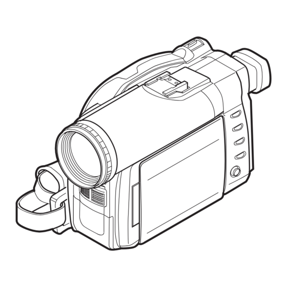
General Description > Name of Parts 2-7 Name of Parts 1 Recording indicator The red indicator will light during recording. 2 Optical 10× zoom lens 3 Lens hood Always remove this lens hood when using generall y available tele-conversion or wide- conversion lens. - Page 19 General Description > Name of Parts 26 BLC (backlight compensation) button Press this button when subject is being li ghted from rear. 27 DISC NAVIGATION button 28 SELECT button 29 MENU button Press this button to display the menu for setting camera functions and Disc Navigation.
-
Page 20: Inserting Disc
General Description > Inserting Disc 2-8 Inserting Disc (1) Inserting disc to DVD video camera/recorder Pr ess down the DISC EJECT button once and r elease it . DISC EJECT button A few moments after the ACCESS/ PC indicator blinks, the cover of disc insertion block will open slightly. - Page 21 General Description > Inserting Disc (3) Replacing disc in round DVD holder Open SIDE A of the Round DVD Holder, and replace the disc in the holder with the SIDE A mark or label sur face facing up, OPEN marks SIDE A taking care not to touch the disc sur face.
-
Page 22: List Of Abbreviations And Terms For Dvd Video Camera/Recorders
General Description > List of Abbreviations and Terms for DVD Video Camera/Recorders 2-9 List of Abbreviations and Terms for DVD Video Camera/Recorders Index Abbreviation/Term Explanation See Dolby AC3. CPRM Content Protection for Recordable Media: Security technology (cross-certification technology) for SD memory card. Design rule for Camera File system standard: This camera file system standard, established by JEIDA (now merged to JEITA). - Page 23 General Description > List of Abbreviations and Terms for DVD Video Camera/Recorders Index Abbreviation/Term Explanation MPEG Motion Picture Experts Group: Standard related to compression of digital video and audio. MPEG2 is a higher standard of MPEG and is applied to video (movie) requiring higher quality.
-
Page 24: Description Of Operation
Description of Operation 3-1 Description of Mechanism (1) Lock mechanism of disc loading block (lock unit) Since the structure of disc loading block in DZ-MV350E is different from that of the lock unit in previous models, it will not open unless a power supply (battery or AC adapter/charger) is connected. - Page 25 Description of Operation > Description of Mechanism (2) Structure schematics 1) Disc cover (includes power switch, speaker and card slot) 2) Lock arm in lock unit 3) DC motor in lock unit 4) Lock unit 5) Disc drive unit 6) Lens cover 7) Hood 8) LCD case U 9) Front cover...
-
Page 26: Description Of Newly Adopted Technology
The formal name is “Secure Digital Memory Card”. The SD Card Association (SDA), founded in 2000, is promoting worldwide adoption of this compact memory card standard. At present, approximately 500 member companies all over the world, including Hitachi, participate in SDA. (2) MultiMediaCard The MMC Association (MMCA: MultiMediaCard Association), founded in 1998, is promoting worldwide adoption of this compact memory card standard. -
Page 27: Standards For Photo Recording On Card
The DPOF standard was jointly proposed by Cannon, Kodak, FUJIFILM and Matsushita in 1998, so that photos recorded on compact memory card could easily be output. DPOF also conforms to storage media other than SD memory card and MultiMediaCard, and is accepted by numerous companies, including Hitachi. 3 - 4... -
Page 28: Software Disc-Protect Function
Description of Operation > Description of Newly Adopted Technology 3-2-3 Software disc-protect function The DZ-MV350E is equipped with a software disc-protect function instead of an erase-prevention mechanism: The erase-prevention mechanism is not provided with new round disc holder because of its structure. -
Page 29: Troubleshooting
Troubleshooting 4-1 Procedure for Troubleshooting Perform troubleshooting in the order shown in Fig. 4-1-1. Updating No improvement No improvement unneeded No message or Check firmware Trouble Check Check Problem guide System reset error code version Diagnosis troubleshooting phenomenon (section 4-2) (section 4-5) appears (section 4-6-1) - Page 30 Troubleshooting > Problem Guide 4-2 Problem Guide Check the following before judging that DZ-MV350E is faulty. Symptom Cause and Correction Power supplies Battery cannot be charged. Is the DC power cord connected to AC adapter/charger? Unplug it. If the DC power cord is connected, the AC adapter/charger will not enter the charge status.
- Page 31 Troubleshooting > Problem Guide Symptom Cause and Correction During recording Recording starts but stops Does dirt or fingerprint adhere to Disc cleaning method: immediately. disc, or is disc scratched? Use soft cloth to clean Clean the disc. If there is still no from inner to outer improvement, replace the disc.
- Page 32 Troubleshooting > Problem Guide Symptom Cause and Correction When connected to PC (when using provided software) No drive icon appears on PC. Is DZ-MV350E turned on? Connect the AC adapter/charger and set the power switch to a position other than "POWER OFF". Is PC connection cable properly plugged in? Plug the PC connection cable connector completely into DZ-MV350E.
- Page 33 Troubleshooting > Problem Guide Symptom Cause and Correction DVD-R disc cannot be played DVD-MovieAlbumSE is exclusively for DVD-RAM disc. When playing back back on DVD- DVD-R disc on PC, use generally available DVD-R disc playback software. MovieAlbumSE Error appears when starting Make sure that your PC display adapter (video card) conforms to DirectX8.1 DVD-MovieAlbumSE Video written to hard disk of...
- Page 34 Troubleshooting > Problem Guide Symptom Cause and Correction Miscellaneous Power does not come on, or Execute system reset (disconnect the battery or AC adapter/charger, and then no operation occurs by use a fine tipped pen, etc. to hold down the RESET button for several seconds). pressing button.
- Page 35 Troubleshooting > Problem Guide Symptom Cause and Correction Disc cover cannot be closed. Is disc correctly loaded? Remove the disc and then reload it. Is round DVD holder being used? A bare disc that is not in round DVD holder, or is in a square cartridge or caddy, cannot be used.
- Page 36 Troubleshooting > Messages and Troubleshooting 4-3 Messages and Troubleshooting Some messages may appear on the LCD screen or in the viewfinder during operation. If a message appears, refer to the following table and perform troubleshooting according to the message. Messages divided by broken lines will automatically appear in sequence from the upper row each time the playback/pause button is pressed (press the center of joystick).
- Page 37 Troubleshooting > Messages and Troubleshooting Cause/condition for Message Troubleshooting message to appear Cannot record photos. Appears if an attempt is made to record Use a DVD-RAM disc or card when photos on DVD-R disc: The specifications recording photos. state that no photo is recordable on DVD-R disc.
- Page 38 Troubleshooting > Messages and Troubleshooting Cause/condition for Message Troubleshooting message to appear Control Information Error. Appears if mismatch has occurred Update the control information. between the recorded video and the (Start Disc Navigation, press the scene information because editing was MENU button, and then execute performed near the limit of disc storage “Update Control Info.”...
- Page 39 Troubleshooting > Messages and Troubleshooting Cause/condition for Message Troubleshooting message to appear DISC ACCESS This message appears during normal Operate DZ-MV350E after the operation process, when DZ-MV350E message disappears. checks whether a proper disc has been loaded or not. It is displayed for a longer time period when the date has changed.
- Page 40 Troubleshooting > Messages and Troubleshooting Cause/condition for Message Troubleshooting message to appear Disc full. Appears if the recording capacity of disc Delete unnecessary scenes, or replace Cannot execute. has reached the limit during editing of the disc. video file. Disc has no data. Appears when the MANU button or Operate DZ-MV350E after the playback button was pressed with no...
- Page 41 Troubleshooting > Messages and Troubleshooting Cause/condition for Message Troubleshooting message to appear Disc overheat. Appears when the temperature inside Set the power switch to “POWER Please retry later. DZ-MV350E, or the temperature of disc, OFF” with the disc loaded, and then is too high, and normal operation cannot leave the DZ-MV350E in a well- be executed.
- Page 42 Troubleshooting > Messages and Troubleshooting Cause/condition for Message Troubleshooting message to appear Finalize may not be Appears if accident, such as power off, Choose “YES” and designate it to complete. occurred during finalizing, and then finalize the disc. Finalize again now? power was turned on again or disc was reloaded.
- Page 43 Troubleshooting > Messages and Troubleshooting Cause/condition for Message Troubleshooting message to appear No more scenes. Appears during user operation; all Operate DZ-MV350E after the Play List was deleted. recorded scenes have been deleted and message disappears. cleared. The specifications stipulate that a play list with no scene on it cannot be held: If all registered scenes have been deleted, the play list will also be deleted.
- Page 44 Troubleshooting > Messages and Troubleshooting Cause/condition for Message Troubleshooting message to appear DPOF is not set to scene Appears if “Slide Show: DPOF” is Specify “Slide Show: All”, or do not specified when a card for which DPOF try slide show. has not been set is loaded.
- Page 45 Troubleshooting > Messages and Troubleshooting Cause/condition for Message Troubleshooting message to appear Write protected. Appears if a DVD-RAM disc that was Release the software disc-protect. Check disc. write-protected for disc units by software disc-protect function is loaded, or if an attempt is made to record on write- protected disc.
- Page 46 Troubleshooting > Self-Diagnosis Function and Troubleshooting 4-4 Self-Diagnosis Function and Troubleshooting Restriction: The information included in this section is exclusively for service personnel. Do not disclose it to persons other than service engineers. The DZ-MV350E is equipped with a self-diagnosis function: If it detects a problem when power is turned on or during operation, it will display a message, replace the content of problem with an error code (4-digit alphanumeric characters), and then store it in flash memory.
- Page 47 Troubleshooting > Self-Diagnosis Function and Troubleshooting (2) Messages for serious problems (Figs. 4-4-3, 4-4-4) These messages appear when solving the problem detected when power is turned on or during operation is not likely by turning power on again or reloading the disc: Error codes (4- Error has occurred.
- Page 48 Troubleshooting > Self-Diagnosis Function and Troubleshooting 4-4-2 Error codes stored in flash memory (1) Displaying error codes and clearing them Display method E r r o r c o d e 1) Use the battery or AC adapter/charger to power DZ- MV350E, and then set the power switch to “VIDEO”.
- Page 49 Troubleshooting > Self-Diagnosis Function and Troubleshooting 4-4-3 Major error codes and troubleshooting Table 4-4-1 shows the error codes that are likely to frequently appear, and troubleshooting when they appear. If error codes other than those listed in Table 4-4-1 appear, check with the factory for troubleshooting.
- Page 50 Troubleshooting > Self-Diagnosis Function and Troubleshooting Table 4-4-1 Major Error Codes and Troubleshooting (2/2) Error code Contents of problem Troubleshooting 3122 Recording on DVD-RAM disc failed. 1) Set the power switch to “POWER OFF”, reattach the battery or AC adapter/charger, and then set the power 3126 Writing data file to disc failed.
-
Page 51: System Resetting/Resetting Camera Functions
Troubleshooting > System Resetting/Resetting Camera Functions 4-5 System Resetting/Resetting Camera Functions The DZ-MV350E has two types of reset function: “System reset” and “Resetting camera functions”. The reset operation will return the various settings to the defaults when the DZ-MV350E was shipped form factory. -
Page 52: System Reset Procedure
Troubleshooting > System Resetting/Resetting Camera Functions Yes: Will be reset Table 4-5-1 Settings to Be Reset (2/2) No: Will not be reset Camera System Default at Item function Setting range Remarks Memo reset factory reset Date Setup Date Mode day/month/ year/month/day PM5:00, year month/day/year 5:00PM,... -
Page 53: Checking Versions Of Firmware And Updating
Troubleshooting > Checking Versions of Firmware and Updating 4-6 Checking Versions of Firmware and Updating The DZ-MV350E stores the 4 types of firmware shown in Table 4-6-1 in flash memory. These firmware programs will be updated whenever necessary to improve the performance of DZ- MV350E. -
Page 54: Updating Firmware
Troubleshooting > Checking Versions of Firmware and Updating (3) Details of information/version display screens When no disc is loaded Table 4-6-2 Details of Information/Version Display Screens Detail Item Display contents Model: DZ-MV3-PAL System: Ver. 1.16 Model Model name Date: 2003/03/14 05:25:37 System Ver. - Page 55 Troubleshooting > Checking Versions of Firmware and Updating During updating, the screens showing that each Firmware Update firmware program is being updated (Figs. 4-6-3, 4-6-4, 4- 6-5), followed by the screen showing that updating is Updating system. complete (Fig. 4-6-6), will appear. However, not all firmware programs need updating Do not turn off power.
-
Page 56: Trouble Diagnosis
4-7 Trouble Diagnosis Information: Although the procedures for disassembling and reassembling the DZ-MV380E are different from those for DZ-MV350E, the contents in “4-7-3 Trouble diagnosis table” still apply to both devices. 4-7-1 Selecting service position For trouble diagnosis, with a few exceptions it is necessary to disassemble the DZ-MV380E and set it to the service position. -
Page 57: Disassembly/Reassembly For Enabling Service Position
Troubleshooting > Trouble Diagnosis 4-7-2 Disassembly/reassembly for enabling service position Prohibition Disconnect the AC adapter/charger of battery pack from the DZ-MV380E. The DZ-MV380E has a built-in laser emitter block. Do not look into it: If Laser beam strikes your eye, it could cause serious damage. To set to service position (A), (B) or (C), remove the following components, referring to “5. - Page 58 Troubleshooting > Trouble Diagnosis (2) Setting to service position (B) (Fig. 4-7-6) Refer to Table 4-7-1 and the MAN and AEL circuit board diagrams: Solder a lead wire of approx. 10 cm to the check point that corresponds to the symptom (except for terminals of IC or connector/ plug).
- Page 59 Troubleshooting > Trouble Diagnosis 8) Connect the L block and AEL circuit board via SAF circuit board. (Fig. 4-7-7) AEL CIRCUIT BOARD L BLOCK CIRCUIT BOARD Fig. 4-7-7 Setting to Service Position (C) (4) Setting to service position (D) (Fig. 4-7-8) Remove the following components, referring to “5.
-
Page 60: Trouble Diagnosis Table
Troubleshooting > Trouble Diagnosis 4-7-3 Trouble diagnosis table Interpreting the trouble diagnosis table: 1) Letters in brackets [ ] in “check points” columns show the name and side of circuit board. Example: [MAN-A] shows that the check point exists on side A of MAN circuit board. 2) If there are multiple check points for one symptom, check the items from the top down. - Page 61 Troubleshooting > Trouble Diagnosis Table 4-7-1 Trouble Diagnosis Table (2/3) Service Troubleshooting due to Symptom Check points Detail of check position check results Error message “NO ----- ----- Error message Check connections of DRF DISC” appears even appears approx. 1 circuit board.
- Page 62 Troubleshooting > Trouble Diagnosis Table 4-7-1 Trouble Diagnosis Table (3/3) Service Troubleshooting due to Symptom Check points Detail of check position check results Conspicuous block noise ----- ----- ----- Replace MAN circuit during movie recording board. Camera image is TL2084 [MAN-A] Check CCD sensor NG: Replace MAN circuit abnormal...
-
Page 63: Procedure For Removing Disc From Faulty Dz-Mv350E
Troubleshooting > Procedure for Removing Disc from Faulty DZ-MV380E 4-8 Procedure for Removing Disc from Faulty DZ-MV380E Information: DZ-MV380E has an accessory shoe equipped with the power/control terminal, and the shape and removal of accessory shoe are different from those for DZ-MV350E. 4-8-1 Item to be checked Connect the AC adapter/charger or charged battery pack, making sure the ACCESS/PC indicator turns off (after the disc rotation stops and the sound showing that the disc lock has been released is... - Page 64 Troubleshooting > Procedure for Removing Disc from Faulty DZ-MV380E 1) Turn the hood (a) in the direction of the (a) Hood [A] M1.7×4 (Black) (b) Filter Piece arrow to remove it. (See Fig. 4-8-1) (c) Lens Cover 2) Remove three screws [A], and then remove (d) Shoe Cover [X] M2×2.5 (Black) the filter piece (b).
-
Page 65: Special Functions
Troubleshooting > Special Functions 4-9 Special Functions Restriction: The information included in this section is exclusively for service personnel: Do not disclose it to persons other than service engineers. 4-9-1 Forced formatting of DVD-RAM disc (1) Application/Symptom Perform this procedure when the Disc Navigation screen does not start normally due to a defect in data on disc and formatting is not possible by the procedure explained in instruction manual. -
Page 66: Disassembly And Reassembly
Disassembly and Reassembly 5-1 Preparations for Disassembly (1) Checking Disc Connect the AC adapter/charger or charged battery pack, and then press the DISC EJECT button to make sure that no disc is inserted. After check, close the disc cover. If the disc cover does not open normally, refer to "4-8 Procedure for Removing Disc from Faulty DZ- MV380E", and open the holder. - Page 67 Disassembly and Reassembly > Order of Disassembly Reading Disassembly Flowchart: After locating the target component in the flowchart, remove all components of the target in sequence, following the arrows (routes) from the top of flowchart. If multiple routes exist to the target component from the top of flowchart, remove all the components on all the routes.
-
Page 68: Disassembly
Disassembly and Reassembly > Disassembly 5-3 Disassembly Information: Numbers in figures are step numbers in disassemble procedure, and letters in brackets [ ] show the types of screw. Letters in brackets ( ) show the name of parts. (a) Adjustment Cover (1) Adjustment Cover (Fig. -
Page 69: Saf Circuit Board And L Block
Disassembly and Reassembly > Disassembly (3) Eyecup, SAF Circuit Board, and L Block (Figs. 5-3-3, 5-3-4) Eyecup (a) 1) Pull the EVF unit 2) Remove the eyecup in the direction of the arrow. SAF Circuit Board (b) and L Block (c) 3) Open the LCD monitor. - Page 70 Disassembly and Reassembly > Disassembly (4) Front Block, FAF Circuit Board, and R Block (Fig. 5-3-5) 1) Open the jack cover (d ), and then remove screw [C] beside the jack. 2) Remove screw [D] from the bottom of front block (a). 3) Remove the front block from R block (c) in the direction of the arrow: Be careful not to damage the FAF circuit board (b) between front block and R block.
-
Page 71: L Cover, L Case And Lcd Block
Disassembly and Reassembly > Disassembly (5) L Cover, L Case and LCD Block (Fig. 5-3-6) (a) L Cover L Cover (a) (b) L Case 1 [E] 1) Remove five screws [E] and then remove the (c) LCD Block LCD block and fulcrum block (d) assembled (d) Fulcrum Block with L case from the L cover. -
Page 72: Lcd Case U, Mr Circuit Board And Fulcrum Block
Disassembly and Reassembly > Disassembly (7) LCD Case U, MR Circuit Board, and Fulcrum Block (Fig. 5-3-8) LCD Case U (a) 1) Insert a fine-tipped screwdriver (e) into the screw hole in fulcrum block, and then turn the screw hole bracket 90° in the direction of the arrow. 2) Turn the fulcrum block 90°... -
Page 73: Disc Cover
Disassembly and Reassembly > Disassembly (8) Disc Cover (Figs. 5-3-9, 5-3-10) 1) Remove four screws [X] and pull up the parts (m) of accessory shoe. After work, reinstall part [m] and screws [X] to the accessory shoe: The accessory shoe is set as a service part, including part [m] and screws [X]. -
Page 74: Usb Circuit Board, Rear Cover, And Hand Strap
Disassembly and Reassembly > Disassembly (9) USB Circuit Board, Rear Cover, and Hand Strap (Fig. 5-3-11) USB Circuit Board (a) 1) Remove screw [D]. 2) Disconnect the flat cable from MAN circuit board (d), and then remove the USB circuit board assembled with USB holder (e) from the R block. -
Page 75: She Circuit Board, Accesory Shoe And Evf Unit
Disassembly and Reassembly > Disassembly (10) SHE Circuit Board, Accessory Shoe, and EVF Unit (Fig. 5-3-12) SHE Circuit Board (a) and Accessory Shoe (b) 1) Disconnect the SHE circuit board from AEL circuit board (d) in the direction of the arrow. 2) Disconnect the two flat cables from SHE circuit board. -
Page 76: Ael And Man Circuit Boards
Disassembly and Reassembly > Disassembly (11) AEL and MAN Circuit Boards (Fig. 5-3-13) 1) Disconnect the flat cable from AEL circuit board (a). 2) Disconnect the SHE circuit board (c) in the direction of the arrow from the AEL circuit board. 3) Disconnect the DRF circuit board (d) in the direction of the arrow from the MAN circuit board. -
Page 77: Camera Block
Disassembly and Reassembly > Disassembly (12) Camera Block (Fig. 5-3-14) 1) Disconnect the SEN circuit board (b) from MAN circuit board (c) in the direction of the arrow. 2) Disconnect the flat cable from AEL circuit board (d). 3) Disconnect the GYR circuit board (e) from SHE circuit board (f). 4) Remove two screws [H]. -
Page 78: Lcd Circuit Board, Backlight, Lcd Unit And Lcd Case
Disassembly and Reassembly > Disassembly (13) LCD Circuit Board, Backlight, LCD Unit , and LCD Case B (Fig. 5-3-15) LCD Circuit Board (a) 1) Unsolder the two points on LCD circuit board. 2) Disconnect the flat cable from LCD circuit board. 3) Remove screw [G], and then remove the LCD circuit board. -
Page 79: Link Bracket, Drive Block And R Case
Disassembly and Reassembly > Disassembly (14) Link Bracket, Drive Block, and R Case (Figs. 5-3-16, 5-3-17, 5-3-18) Link Bracket (a) (Fig. 5-3-16) 1) Remove two screws [K], and then remove the link bracket. Drive Block (b) and R Case (c) (Figs. 5-3-16, 5-3-17, 5-3-18) 2) Remove screw [D]. -
Page 80: Fulcrum Cover U And Fulcrum Cover B
Disassembly and Reassembly > Disassembly (15) Fulcrum Cover U and Fulcrum Cover B (Fig. 5-3-19) 1) Remove two screws [D] and then remove the (a) Fulcrum Cover U fulcrum cover U (a) and fulcrum cover B (b). (b) Fulcrum Cover B 1 [D] [D] M1.6×2.5 (Black) Fig. -
Page 81: Loader, Drf Circuit Board, Disc Drive Unit, And Lock Unit
Disassembly and Reassembly > Disassembly (17) Loader, DRF Circuit Board, Disc Drive Unit, and Lock Unit (Fig. 5-3-21) Loader (a) 1) Remove two screws [M], and then remove the loader from disc drive unit. Note: Do not subject the loader to undue force: If the loader is damaged, discs cannot be inserted or recognized. -
Page 82: Adjustment
Adjustment 6-1 Creating Reference Data The reference data is necessary for adjustment: The adjustment program will not operate normally without it. Before adjustment, be sure to create the reference data, using the same model (with normal camera block) as the one to be adjusted. See section 6-1-1 and subsequent sections for details. - Page 83 Adjustment > Creating Reference Data 6-1-1 List of Jigs and Tools used when Creating Reference Data Adjustment floppy disk Skylark connection jig Note: Create the data using the adjustment data Parts No. TP14161 downloaded from Intranet. If downloading is not possible, obtain the floppy disk with Parts No.
- Page 84 Adjustment > Creating Reference Data 6-1-2 Power Supply and Materials for Creating Reference Data 1) DVD video camera/recorder that is the same model as the one to be adjusted and whose camera block is operating normally. Note: It is recommended that you use a brand-new unit of the same model when creating the reference data.
- Page 85 Adjustment > Creating Reference Data LIGHT BOX 30 - 50cm FRONT SECTION REMOVE THE ADJUSTMENT COVER [Refer to "(1) Adjustment To VIDEO IN COLOR cover" in "5-3 Disassembly"] TERMINAL AV/S INPUT/ MONITOR OUTPUT CABLE RESET SKYLARK BUTTON CONNECTION DC POWER To AC CORD AC ADAPTER/...
- Page 86 Adjustment > Creating Reference Data 6-1-4 Settings when Creating Reference Data When the connections for creating reference data are complete, set the DVD video camera/recorder and test equipment as follows: 1) Make sure that no disc or card is inserted: Neither is necessary when creating reference data. 2) Set the power switch to “VIDEO”, and set the DVD video camera/recorder to the recording pause status: After that operate the DVD video camera/recorder while watching the LCD monitor screen.
- Page 87 Adjustment > Creating Reference Data 6-1-5 Storing or Deleting Adjustment Program Information: The adjustment program also includes a program for creating reference data. (1) Storing 1) Start the PC. 2) Start Explorer and create a new folder in HDD of PC. The name “map03w” is recommended for the folder: If a folder with the same name exists, give the folder a similar name that is easily understandable.
- Page 88 DVD video camera/recorder or DSP-R jig is powered. 2) If there is a problem in connections or power supply, Copyright (C) HITACHI, Ltd 2003 take care of the problem, and then click the YES button to proceed with the MODEL SELECT screen.
- Page 89 Adjustment > Creating Reference Data 6) Choose the radio button of corresponding model name in MODEL SELECT screen. MODEL SELECT screen. MANUAL ADJUSTMENT PROGRAM for SERVICE STATION 7) Click the ENTER button in MODEL SELECT screen, MODEL SELECT and then proceed with the SETUP MENU screen. ×...
- Page 90 Adjustment > Creating Reference Data 6-1-7 Creating Reference Data Start the setup program referring to “6-1-6 Starting and Terminating Reference Data Creation Program”. For subsequent operation, operate the PC mouse while watching the PC monitor screen. Information: SETUP MENU screen. It takes approx.
- Page 91 Adjustment > Creating Reference Data 8) Check WHITE BALANCE ABS on the SETUP MENU SETUP MENU screen. screen. MANUAL ADJUSTMENT PROGRAM for SERVICE STATION 9) Repeat steps 2)-5). SETUP MENU 10) Click the RETURN button on SETUP MENU screen. Matrix 11) The ALL SETUP FINISH dialog will appear: Click the White Balance OK button to complete the creation of reference data.
-
Page 92: Setups For Adjustment
Adjustment > Setups for Adjustment 6-2 Setups for Adjustment 6-2-1 Checking Reference Data Before starting adjustment, check whether it will be necessary to create the reference data or not, referring to the flowchart below: Have you ever performed adjustment of this model? Does the “map03w”... - Page 93 Adjustment > Setups for Adjustment 6-2-3 Test Equipment, Power Supply and Charts for Adjustment 1) Color bar chart Color Bar Chart 2) 3100 K light box (maintenance is necessary) 3) Backfocus chart 4) Color monitor (color TV with AV input jacks) 5) Oscilloscope 6) Vectorscope 7) Digital voltmeter...
- Page 94 Adjustment > Setups for Adjustment LIGHT BOX VECTORSCOPE OUTPUT INPUT 30 - 50cm OSCILLOSCOPE CH1 CH2 TRIG FRONT SECTION REMOVE THE ADJUSTMENT COVER [Refer to "(1) Adjustment cover" in "5-3 Disassembly"] AV/S INPUT/ OUTPUT CABLE RESET SKYLARK BUTTON CONNECTION When using an DC POWER To AC oscilloscope only...
- Page 95 Adjustment > Setups for Adjustment 6-2-5 Settings for Adjustment When the connections for adjustment are complete, set the DVD video camera/recorder and test equipment as follows: (1) Setting the DVD video camera/recorder Information: This item is the same as when creating reference data. 1) Make sure that no disc or card is inserted: Neither is necessary for adjustment.
- Page 96 Adjustment > Setups for Adjustment (2) Setting test equipment The names of switches, etc. of test equipment may vary depending on the manufacturer and model. Some switches in addition to those shown below may have to be set: See the instruction manual of test equipment for details.
- Page 97 EXIT 5) Click the OK button on the COMMUNICATION PORT SETTING screen, and then proceed with the MODEL SELECT screen. Copyright (C) HITACHI, Ltd 2003 Note: POWER OR CONNECTION ERROR If the POWER OR CONNECTION ERROR dialog appears , dialog...
- Page 98 Adjustment > Setups for Adjustment 6) Choose the radio button of corresponding model name in MODEL SELECT screen. MANUAL ADJUSTMENT PROGRAM for SERVICE STATION MODEL SELECT screen. 7) Click the ENTER button in MODEL SELECT screen, MODEL SELECT and then proceed with the ADJUST MENU screen. ×...
-
Page 99: List Of Adjustment Items
Adjustment > List of Adjustment Items 6-3 List of Adjustment Items 6-3-1 Adjustment Program Hierarchy Diagram Communication Port Setting Model Select MANUAL ADJUSTMENT PROGRAM for SERVICE STATION Data Initialize × × × × MODEL NAME: ADJUST MENU DATA INITIALIZE VIDEO LEVEL Video Level BURST LEVEL SAMPLING PULSE... - Page 100 Adjustment > List of Adjustment Items 6-3-2 List of Adjustments Needed After Replacing Major Components Major Components IC1301 IC1401 IC3701 IC6103 Lens unit Item circuit unit IC1302 IC1402 [For DZ-MV350A/ board unit IC1403 MV350E] Data Initialize Video Level Burst Level Sampling Pulse Autofocus Auto Iris Control...
- Page 101 Adjustment > List of Adjustment Items 6-3-3 Purpose of Adjustments and Incompleted Phenomenon Item Purpose Incompleted Phenomenon Data Initialize To initialize EEPROM. ------------ Video Level To set the video output level. The picture becomes dark or whitish. Burst Level To set the burst level. Sampling Pulse To measure the delay time in sampling Diagonal beats and horizontal noise occur.
-
Page 102: Adjustment Procedure
Adjustment > Adjustment Procedure 6-4 Adjustment Procedure Start the adjustment program referring to “6-2-6 Starting and Terminating Adjustment Program”. For the subsequent operation, operate the PC mouse while watching the PC monitor screen. Information: 1) Display ×××× on subsequent PC screen shows the model name. 2) The numbers on PC screens show the operational procedure. - Page 103 Adjustment > Adjustment Procedure ADJUST MENU screen 6-4-2 Video Level MANUAL ADJUSTMENT PROGRAM for SERVICE STATION ×××× Preparations: MODEL NAME: 1) Connect the oscilloscope CH1 to video out. ADJUST MENU DATA INITIALIZE 2) Switch the oscilloscope V-MODE to “CH1” and VIDEO LEVEL TRIGGER SOURCE to “CH1”.
- Page 104 Adjustment > Adjustment Procedure ADJUST MENU screen 6-4-3 Burst Level MANUAL ADJUSTMENT PROGRAM for SERVICE STATION ×××× Preparations: MODEL NAME: 1) Connect the oscilloscope CH1 to video out. ADJUST MENU DATA INITIALIZE 2) Switch the oscilloscope V-MODE to “CH1” and VIDEO LEVEL TRIGGER SOURCE to “CH1”.
- Page 105 Adjustment > Adjustment Procedure ADJUST MENU screen 6-4-4 Sampling Pulse MANUAL ADJUSTMENT PROGRAM for SERVICE STATION ×××× Note: MODEL NAME: ADJUST MENU Start this adjustment after the circuit operation is DATA INITIALIZE stabilized, e.g., after leaving the DVD video camera/ VIDEO LEVEL recorder for at least one hour at normal temperature, and BURST LEVEL...
- Page 106 Adjustment > Adjustment Procedure ADJUST MENU screen 6-4-5 Autofocus MANUAL ADJUSTMENT PROGRAM for SERVICE STATION Preparations: ×××× MODEL NAME: 1) Set the backfocus chart as shown in Fig. 6-4-3. ADJUST MENU 2) Point at backfocus chart 1500mm ± 5 mm away from the DATA INITIALIZE VIDEO LEVEL lens surface: Measure the distance precisely.
- Page 107 Adjustment > Adjustment Procedure 6-4-6 Auto Iris Control ADJUST MENU screen MANUAL ADJUSTMENT PROGRAM for SERVICE STATION Preparation: ×××× MODEL NAME: Set zoom to wide-angle end, and point at light box without ADJUST MENU chart, filling the screen. DATA INITIALIZE VIDEO LEVEL Procedure: BURST LEVEL...
- Page 108 Adjustment > Adjustment Procedure 6-4-7 Matrix ADJUST MENU screen MANUAL ADJUSTMENT PROGRAM for SERVICE STATION Preparation: ×××× MODEL NAME: Point at light box without chart, filling the screen. ADJUST MENU Prepare the C12 light balancing filter (set-up rings): Attach DATA INITIALIZE VIDEO LEVEL it during adjustment.
- Page 109 Adjustment > Adjustment Procedure 6-4-8 Chroma Gain Preparation: Point at light box without chart, filling the screen. Prepare the color bar chart: Use it during adjustment. Procedure: 1) Press the MENU button on DVD video camera/recorder, and use the joystick to specify “White Bal.: Set”...
- Page 110 Adjustment > Adjustment Procedure 7) Click the GAIN UP or GAIN DOWN button in ROUGH CHROMA GAIN ADJUSTMENT screen ADJUSTMENT box so that the value of red vector or MANUAL ADJUSTMENT PROGRAM for SERVICE STATION red level approaches that in Table 6-4-1. Click the CHROMA GAIN ADJUSTMENT button at approx.
- Page 111 Adjustment > Adjustment Procedure 6-4-9 Stabilizer Note: Perform STABILIZER only after replacing any component on the GYR circuit board or executing “Data Initialize”. This item STABILIZER is not an adjustment, but is performed to write the camera shake correction value contained in adjustment program to EEPROM. Although the camera shake correction value written to EEPROM is an adjustment value inherent in individual devices when shipped from the factory, the camera shake correction value contained in adjustment program is an average value set at the factory.
- Page 112 Adjustment > Adjustment Procedure 6-4-10 Spot Noise Information: 1) The SPOT NOISE adjustment compensates for bright points that appear on the screen, and these are caused by a defect in pixel of CCD (image sensor) that may occur when DVD video camera/recorder is used under particular conditions or for a long time.
- Page 113 Adjustment > Adjustment Procedure 6-4-11 LCD Note: 1) Perform LCD only after replacing the MAN circuit board or 2.5 LCD Unit, or executing “Data Initialize”. 2) Neither light box nor chart is needed for LCD adjustment. Before performing any adjustments for LCD, be sure to shift the DVD video camera/recorder to the test mode using the procedure below, and then display the LCD ADJUSTMENT MENU.
- Page 114 Adjustment > Adjustment Procedure LCD ADJUSTMENT MENU screen (1) LCD PLL MANUAL ADJUSTMENT PROGRAM for SERVICE STATION Preparation: Connect the frequency counter to “LCD-HDD (pin 9)” of LCD ADJUSTMENT MENU Skylark Connection jig. LCD ADJUSTMENT MENU Procedure: 1) Check PLL on the LCD ADJUSTMENT MENU screen. BRIGHT 2) Click the EXECUTE button on LCD ADJUSTMENT MENU screen to proceed with the PLL ADJUSTMENT...
- Page 115 Adjustment > Adjustment Procedure LCD ADJUSTMENT MENU screen (2) LCD Brightness MANUAL ADJUSTMENT PROGRAM for SERVICE STATION Preparations: 1) Connect the oscilloscope CH2 to “LCD-G (pin 5)” of LCD ADJUSTMENT MENU Skylark Connection jig. LCD ADJUSTMENT MENU 2) Switch the oscilloscope V-MODE to “CH2”: Leave the TRRIGER SOURCE in “CH1”...
- Page 116 Adjustment > Adjustment Procedure LCD ADJUSTMENT MENU screen (3) LCD Contrast MANUAL ADJUSTMENT PROGRAM for SERVICE STATION Preparations: 1) Connect the oscilloscope CH2 to “LCD-G (pin 5)” of LCD ADJUSTMENT MENU Skylark Connection jig. LCD ADJUSTMENT MENU 2) Switch the oscilloscope V-MODE to “CH2”: Leave the TRRIGER SOURCE in “CH1”...
- Page 117 Adjustment > Adjustment Procedure LCD ADJUSTMENT MENU screen (4) LCD White Balance MANUAL ADJUSTMENT PROGRAM for SERVICE STATION Preparations: 1) Connect the oscilloscope CH1 to “LCD-R (pin 3)” of LCD ADJUSTMENT MENU Skylark Connection jig. LCD ADJUSTMENT MENU 2) Connect the oscilloscope CH2 to “LCD-G (pin 5)” of Skylark Connection jig.
- Page 118 Adjustment > Adjustment Procedure 7) Connect the oscilloscope CH1 to “LCD-B (pin 7)” of SUB BRIGHT BLUE ADJUSTMENT screen. Skylark Connection jig. MANUAL ADJUSTMENT PROGRAM for SERVICE STATION 8) Use the same procedure as in step 3) to equalize levels a and b of the waveform.
- Page 119 Adjustment > Adjustment Procedure 6-4-12 EVF Note: 1) Perform EVF only after replacing IC3701 and its peripheral components, MAIN circuit board or EVF unit, or executing “DATA Initialize”. 2) Neither light box nor chart is needed for EVF adjustment. Before performing any adjustments for EVF, be sure to shift the DVD video camera/recorder to the test mode using the procedure below, and then display the EVF ADJUSTMENT MENU.
- Page 120 Adjustment > Adjustment Procedure (1) BL DET Check Note: Be sure to take note of the resulting value of this check because the check value will be needed when EVF adjustment is completed. There are two types of EVF unit mounted in these DVD video camera/recorder series models: The backlight characteristics of the two types are different.
- Page 121 Adjustment > Adjustment Procedure (3) EVF Brightness EVF ADJUSTMENT MENU screen Preparations: MANUAL ADJUSTMENT PROGRAM for SERVICE STATION 1) Connect the oscilloscope CH1 to video output. EVF ADJUSTMENT MENU 2) Connect the oscilloscope CH2 to “EVF-G (pin 4)” of EVF ADJUSTMENT MENU Skylark Connection jig.
- Page 122 Adjustment > Adjustment Procedure EVF ADJUSTMENT MENU screen (4) EVF Contrast MANUAL ADJUSTMENT PROGRAM for SERVICE STATION Preparations: 1) Connect the oscilloscope CH2 to “EVF-G (pin 4)” of EVF ADJUSTMENT MENU Skylark Connection jig. Confirm the CH1 connection to EVF ADJUSTMENT MENU video out.
- Page 123 Adjustment > Adjustment Procedure EVF ADJUSTMENT MENU screen (5) EVF White Balance MANUAL ADJUSTMENT PROGRAM for SERVICE STATION Preparations: 1) Connect the oscilloscope CH1 to “EVF-R (pin 2)” of EVF ADJUSTMENT MENU Skylark Connection jig. EVF ADJUSTMENT MENU 2) Connect the oscilloscope CH2 to “EVF-G (pin 4)” of Skylark Connection jig.
- Page 124 Adjustment > Adjustment Procedure 7) Connect the oscilloscope CH1 to “EVF-B (pin 6)” of SUB BRIGHT BLUE ADJUSTMENT screen. Skylark Connection jig. MANUAL ADJUSTMENT PROGRAM for SERVICE STATION 8) Use the same procedure as in step 3) to equalize levels a and b of the waveform.
-
Page 125: Exploded View And Parts List
Exploded View and Parts List 7-1 Exploded Views Note: Components without any numbers in exploded views had not been assigned as service parts as of the date of issue 7-1-1 Main Section of this manual. USB CIRCUIT BOARD DVD DRIVE UNIT [Component [Unit Replacement SHE CIRCUIT... -
Page 126: Lcd Block Section
7-1-2 LCD Block Section MR CIRCUIT BOARD [Component Replacement] LCD CIRCUIT BOARD [Component Replacement] 7-1-3 Camera Block Section SEN CIRCUIT BOARD [Component Replacement] GYR CIRCUIT BOARD [Component Replacement] 7 - 2... -
Page 127: Replacement Parts List
7-2 Replacement Parts List 7-2-1 Mechanical Parts List SYMBOL SYMBOL P-NO DESCRIPTION P-NO DESCRIPTION MECHANISM SECTION ACCESSORIES PWB ASSY MAN-H ADPTOR,AC DVD DRIVE MECHA(PC3A) CORD,AC [For (AU)] CORD,AC [For (UK)&(SWH)] TERMINAL,SHOE CORD,AC [Except For (AU),(UK)&(SWH)] HOLDER,USB CORD,AVS CASE,FRONT RING(O) CORD,DC COVER,MICROPHONE REMOTE HAND SET CABLE,USB... - Page 128 THE UPDATED PARTS LIST FOR THIS MODEL IS AVAILABLE ON ESTA...
-
Page 129: Schematic, Circuit Board And Block Diagrams
Schematic, Circuit Board and Block Diagrams 1. Wiring Diagram DISC DRIVE UNIT LENS UNIT PG2302 70PIN FOCUS MOTOR/ ZOOM MOTOR/IRIS 4PIN PG9303 PG9501 6PIN PG9403 SLID TEST MOTOR PG1001 PG9701 16PIN PG2301 BATTERY 16PIN TERMINAL SPINDLE PG9404 PG9103 70PIN MOTOR 15PIN PG2001 REAR COVER... -
Page 130: Schematic Diagrams
2. Schematic Diagrams 2-1 SEN Schematic Diagram -6.5 IC1001 ICX288BK (IMAGE SENSOR) 14.2 (QC) 11.5 (QC) 10.7 (8B) 10.7 11.5 PG2001 CODE PART NAME 2SC2620 UN9212 ONE VOLTAGE:PB OR REC MODE TWO VOLTAGES:PB AND (REC) MODE - 2 -... -
Page 131: Frt Schematic Diagram
2-2 FRT Schematic Diagram 2-3 FAF Schematic Diagram CN1801 CODE PART NAME 2SC5383T11 2SD2345-S DTC114YE MA132WA ONE VOLTAGE:PB OR REC MODE TWO VOLTAGES:PB AND (REC) MODE BOARD To BOARD PG1801 [AEL] PG7003 R1812 0 RECEIVER 0(3) 2-4 SAF Schematic Diagram R1802 0 L CASE BOARD To BOARD... -
Page 132: Gyr Schematic Diagram
2-5 GYR Schematic Diagram 2-6 SHE Schematic Diagram CODE PART NAME XP4501 ONE VOLTAGE:PB OR REC MODE TWO VOLTAGES:PB AND (REC) MODE ACCESSORY SHOE VL1220/F3A PG0154 CN1401 UNIT 0-3.1 0-3.1 1.3 1.3 - 4 -... -
Page 133: Board To Board [Ael] Schematic Diagram
2-7 Board To Board [AEL] Schematic Diagram PG3401 CODE PART NAME FR/FQ/FS 2SA1774RS UMH9N DTC114YE NDS336P MA133 R7077 R7088 LENS DRIVE 1A-21A ONE VOLTAGE:PB OR REC MODE TWO VOLTAGES:PB AND (REC) MODE (MP) FOR ADJUSTMENT. BM10696R CN7003 BM10696R AUDIO 1C-42C CN7004 BM10696R BM10696R... -
Page 134: Lens Drive [Ael] Schematic Diagram
2-8 Lens Drive [AEL] Schematic Diagram (AE) (FR) PB: 0 REC: (64) PB: 0 REC: PB: 0.2 REC: PB: 0 REC: HALL ZOOM MOTOR DRIVE PB: 0 CONT. REC: FOCUS MOTOR EXT2 DRIVE IRIS MOTOR 0.4(1.9) DRIVE PB: 0 REC: AF/ZOOM IRIS PB: 0... -
Page 135: Audio [Ael] Schematic Diagram
2-9 Audio [AEL] Schematic Diagram REC: 0 R6331 2.0 3.9 BE10391R BE10391R R6209 2.3 0 BOARD To BOARD 1C-3C C6126 C6129 3.1 3.1 1.4 1.4 1.4 1.4 1.4 1.4 1.4 1.4 1.4 TL6101 TL6102 CODE PART NAME FR/FQ/FS 2SA1774RS YR/YQ/YS 2SD2216 DTC124EE DTC114YE MA132K... -
Page 136: Evf [Ael] Schematic Diagram
2-10 EVF [AEL] Schematic Diagram R3717 R3716 12.0 12.0 TL3719 11.0 [TYPE 8E] C3738 0.01 EVF DRIVER R3731 C3737 0.01 C3736 0.01 R3718 0 R3719 0 [TYPE 8A] R3736 BOARD To BOARD 1B-14B R3732 R3733 TYPE 8A TYPE 8E R3734 C3706 0.01uF Not Provided... -
Page 137: Lcd Schematic Diagram
2-11 LCD Schematic Diagram INVERTER TRANS 15.0 CODE PART NAME 2SA1774RS CAUTION BACK DTC114YE LIGHT RISK OF ELECTRIC SHOCK ONE VOLTAGE:PB OR REC MODE TWO VOLTAGES:PB AND (REC) MODE 15.0 12.0 12.0 CN3401 11.3 LCD_ADJ 12.0 LCD DRIVER LCD_ON LCD_ROUT LCD_GOUT LCD_BOUT 0.1 1.5 1.3 2.1... -
Page 138: Mr Schematic Diagram
2-12 MR Schematic Diagram 2-14 DRF Schematic Diagram VOLTAGE:READ AND (WRITE) MODE. REVERSE AN48800A CN3401 OPEN/CLOSE AN48800A PG3403 2-13 USB Schematic Diagram DISC DRIVE UNIT PG2002 (DRV-PG9701) 180UH BL8102 PC TERMINAL PG5001 - 10 -... -
Page 139: Ic Block Diagrams
IC3401 2-15 IC Block Diagram CXA3582R LCD DRIVER MODE PICTURE Gain PICTURE PICTURE PSIG- BRIGHT MATRIX SYNC IN COLOR DA OUT MUE COLOR G OUT R,G,B G DC DET USER- GAMMA1 SUB- CONTRAST CONTRAST BRIGHT GAMMA2 BRIGHT TRAP FILTER R OUT USER- CONTRAST BRIGHT... - Page 140 IC3701 CXA3503R EVF DRIVER GND3 +12.0V +12.0V +3.0V G OUT OSD RGB TST15 G DC DET FILTER CONTRAST USER-BRIGHT CONT U-BRT OSD B R OUT FILTER TRAP GAMMA OSD R BIAS R DC DET WHITLIM CLAMP SUB-CONT R OSD G B OUT SUB-CONT B BLK-LIM...
-
Page 141: Circuit Board Diagram
3. Circuit Board Diagrams 3-2 SHE Circuit Board Diagram 3-1 SEN Circuit Board Diagram CN0152 SEN -SIDE A- [PATTERN No.JD1157-2] IC1001 SHE -SIDE B- SHE -SIDE A- [PATTERN No.JD1157-2] [PATTERN No.JD1157-2] SEN -SIDE B- [PATTERN No.JD1157-2] - 13 -... -
Page 142: Frt Circuit Board Diagram
3-3 FRT Circuit Board Diagram 3-4 FAF, SAF Circuit Board Diagrams CN1801 CN7003 FAF -SIDE A- [PATTERN No.JD1157-2] JD1157 FRT -SIDE A- FAF -SIDE B- [PATTERN No.JD1157-2] [PATTERN No.JD1157-2] CN8012 CN7004 SAF -SIDE A- [PATTERN No.JD1157-2] JD1157 SAF -SIDE B- FRT -SIDE B- [PATTERN No.JD1157-2] [PATTERN No.JD1157-2]... -
Page 143: Gyr Circuit Board Diagrams
3-5 GYR Circuit Board Diagram 3-6 DRF Circuit Board Diagram CN1401 GYR -SIDE A- [PATTERN No.JD1157-2] DRF -SIDE A- DRF -SIDE B- [PATTERN No.JD1157-2] [PATTERN No.JD1157-2] GYR -SIDE B- [PATTERN No.JD1157-2] - 15 -... -
Page 144: Mr Circuit Board Diagram
3-7 MR Circuit Board Diagram 3-8 USB Circuit Board Diagram CN8101 CN3401 USB -SIDE A- [PATTERN No.JD1157-2] USB -SIDE B- [PATTERN No.JD1157-2] MR -SIDE A- MR -SIDE B- [PATTERN No.JD1157-2] [PATTERN No.JD1157-2] - 16 -... -
Page 145: Ael Circuit Board Diagram
3-9 AEL Circuit Board Diagram TL3719 TL7041 TL6102 TL6101 1000p 0.047 1000p 0.047 TYPE 8A TYPE8E C3706 0.01uF Not Provided 560p C3707 0.01uF Not Provided C3708 0.01uF Not Provided C3736 Not Provided 0.01uF C3737 Not Provided 0.01uF C3738 Not Provided 0.01uF R3707 100k... -
Page 146: Lcd Circuit Board Diagram
3-10 LCD Circuit Board Diagram TL3462 TL3461 BACK LIGHT CAUTION TL3418 RISK OF ELECTRIC SHOCK [PATTERN No.JA2104-4] - 18 -... -
Page 147: Man Circuit Board Diagram
3-11 MAN Circuit Board Diagram TL0520 TL0519 TL0502 TL1544 TL2004 TL0521 TL0501 TL0518 TL1543 33(4.8) 38(4.8) 32(4.8) 39(4.8) 31(4.8) 40(4.8) 30(4.8) 41(4.8) 28(2.5) 43(2.5) 26(3.1) 1- 5 (3.1) 25(3.1) (8.0) TL0517 TL1547 F0502 (K:1.5A/32V) F0503 (K:1.5A/32V) (7.8) (7.8) (7.8) F0504 (K:1.5A/32V) F0501 TL0512... -
Page 148: Drv Circuit Board Diagram
3-12 DRV Circuit Board Diagram (3.2) (3.3) (3.3) (3.3) (3.3) (3.3) (3.3) (4.6) (4.6) (3.0) (4.6) (3.3) (4.8) (4.7) (4.8) (3.3) (4.8) (4.8) (2.5) (4.8) (4.8) (4.8) (4.8) (4.8) (4.7) (4.7) (4.6) (3.2) (4.6) (4.6) (3.3) (4.8) (4.6) (4.6) (4.8) (4.8) (4.7) (4.5) -
Page 149: Sid Circuit Board Diagram
3-13 SID Circuit Board Diagram 3-14 HDM Circuit Board Diagram Information of MAN, DRV, SID and HDM Circuit Boards (4.8) During servicing, replace the entire MAN circuit board, and the entire disc drive unit, including the DRV, SID and HDM circuit boards. -
Page 150: Identification Of Parts Location
3-15 Identification of Parts Location Symbol Parts Symbol Parts Symbol Parts Symbol Parts Symbol Parts Symbol Parts Symbol Parts Symbol Parts Symbol Parts Location Location Location Location Location Location Location Location Location R3435 C3895 A-3D C6323 A-1B Q3892 A-2E R3705 A-2E R6135 A-2C... -
Page 151: Block Diagrams
4. Block Diagrams 4-1 Video/Audio Signal Process Section Block Diagram IC1504 OPERATION EEPROM IC0501 : REC VIDEO/CCD OUT IC3701 : PB VIDEO EVF UNIT EVF DRIVER AC ADPTER/ POWER CHARGER OR CONTLOR : EXT.INPUT VIDEO BATTERY PACK [Refer to power-1] IC1401, REAL TIME IC1402... -
Page 152: Video/Audio Signal Process Section
4-2 Disc Drive Section Block Diagram 8cm DVD-RAM/DVD-R DISC Video/Audio Disc Drive Unit Signal Process Section Head SPINDLE MOTOR SDRAM ANALOG FRONT END LASER DATA IC2006 STROBE CAMERA DSP & DIODE MPEG2 CODEC LASER DIODE Record DRIVE DRIVE DSP (SERVO/DSP/ FRONT MONITOR ATAPI/ DET. -
Page 153: Disc Drive Section
4-3 Power-1 Block Diagram PG7002 PG0501 PG1501 PG7001 ADJUSTMENT SYS3V F0501 IC1502 SYS3V SYS3V BATTERY Q1302 IC1301 TERMINAL 8-12 AF5V IC1505 IC1503 AF+B 12, 54 B/U3V AF/ZOOM/ B/U3V IRIS REAR DRIVE LEN3V L6301 78, 79 78, 79 COVER 1.6V LEN5V 1.6V REG. - Page 154 4-4 Power-2 Block Diagram DISC DRIVE UNIT PG2302 PG9701 PG9301 PG9401 30-33, 30-33, 7, 22, 3, 4 3, 4 38-41 38-41 IC9301 25, 26 25, 26 IC9401 28, 43 28, 43 IC9501 IC9502 IC9602 IC9007 2.5V IC9402 16, 17, 32, 34, 11, 23, 50, 44, 49, 73, 82...
- Page 155 Fax: +49- 89-991 80-224 Fax: 93 491 3513 Hotline: +49-180-551 25 51 (12ct/min) Email: atencion.cliente@hitachi-eu.com Email: HSE- DUS.service@hitachi-eu.com HITACHI EUROPE srl HITACHI HOME ELECTRONICS (NORDIC) AB Via Tommaso Gulli N.39, 20147 Box 77 S-164 94 Kista Milano, Italia SWEDEN ITALY...
Need help?
Do you have a question about the DZMV380EAU and is the answer not in the manual?
Questions and answers