Table of Contents
Advertisement
Quick Links
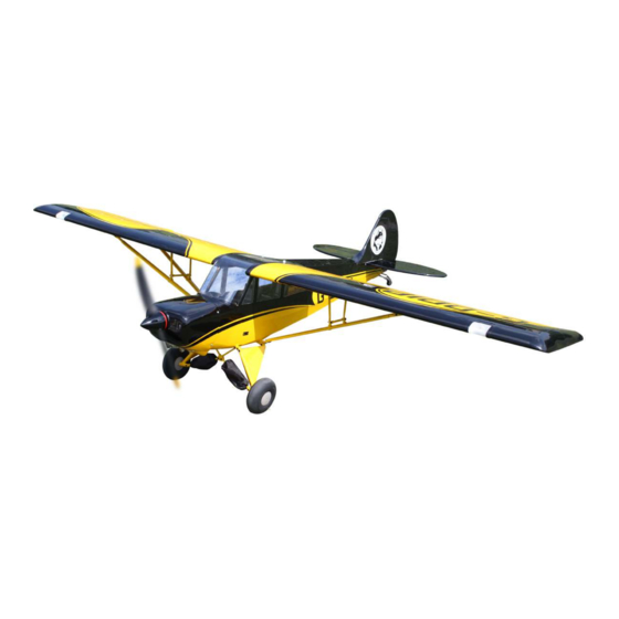
Code : SEA 180N
ASSEMBLY MANUAL
Wingspan------------------------- 80.0 in------------------ 203.0 cm
Wing Arena----------------------- 922.3 sq.in------------ 59.5 sq.dm
Flying Weight-------------------- 11.5 lbs----------------- 5.2 kg
Lenght----------------------------- 50.0 in------------------ 127.0 cm
Recommended engine size-----15-20cc
Radio------------------------------- 6 channels with 7 servos
1
Advertisement
Table of Contents

Subscribe to Our Youtube Channel
Related Manuals for Seagull Models Aviat A-1C Christen Husky 80


Summary of Contents for Seagull Models Aviat A-1C Christen Husky 80
- Page 1 Code : SEA 180N ASSEMBLY MANUAL Wingspan------------------------- 80.0 in------------------ 203.0 cm Wing Arena----------------------- 922.3 sq.in------------ 59.5 sq.dm Flying Weight-------------------- 11.5 lbs----------------- 5.2 kg Lenght----------------------------- 50.0 in------------------ 127.0 cm Recommended engine size-----15-20cc Radio------------------------------- 6 channels with 7 servos...
-
Page 2: Kit Contents
Aviat A-1C Christen Husky 80” wingspan size 15-20cc Instruction Manual. INTRODUCTION Aviat A-1C Christen Husky 80” wingspan size 15- hank you for choosing the 20cc Aviat A-1C Christen Husky 80” wingspan size 15- ARTF by SG MODELS . he 20cc was designed with the intermediate/advanced sport lyer in mind. -
Page 3: Additional Items Required
HINGING THE FLAP KIT CONTENTS Aviat A-1C Christen Husky SEA180N 80” wingspan size 15-20cc 1. Fuselage 2. Wing set (2) 3. Tail set (2) 4. Canopy (2) 5. Cowling 6. Wing tube 7. Landing gear 8. Tail wheel 9. Fuel tank 10. - Page 4 Aviat A-1C Christen Husky 80” wingspan size 15-20cc Instruction Manual. Use sandpaper to scuf the bottom of the aileron and lap control horns. Use a paper towel and isopropyl alcohol to remove any oils or debris from the control horns.
- Page 5 Before the epoxy fully cures, remove the tape from around the control horn. his will allow the epoxy to low around the control horn, creating a small ilet between the control horn and surface for a iished look and secure bond. Remove the control horns from the control surfaces.
- Page 6 Aviat A-1C Christen Husky 80” wingspan size 15-20cc Instruction Manual. Flap control horn INSTALL LED LIGHT Please study images below. Led Light Lipo 3S C/A glue C/A glue...
-
Page 7: Installing The Aileron Servos
INSTALLING THE AILERON SERVOS Use drill bit in a pin vise to drill the mouting holes in the blocks. 1.5mm Apply 2-3 drops of thin C/A to each of the mounting holes. Allow the C/A to cure without using accelerator. Ailerons servo Flap servo Minimum servo spec. - Page 8 Aviat A-1C Christen Husky 80” wingspan size 15-20cc Instruction Manual. Secure the servo to the aileron hatch using Phillips screwdriver and the screws provided with the servo. Apply 1-2 drops of thin C/A to each of the mounting tabs. Allow the C/A to cure without using accelerator.
-
Page 9: Aileron Pushrod Installation
Set the aileron hatch in place and use a Phillips screw driver to install it with four M3 lock nut. M3 clevis. wood screws. 2x10mm AILERON PUSHROD INSTALLATION Please see below pictures. INSTALLING THE FLAP SERVO Repeat the procedure for the lap servo. 60mm... -
Page 10: Installing The Fuselage Servos
Aviat A-1C Christen Husky 80” wingspan size 15-20cc Instruction Manual. INSTALLING THE FLAP PUSHROD Repeat the procedure for the aileron pushrod. Rudder servo Tail wheel 40mm hrottle servo Elevator servo M3 lock nut M3 clevis Secure the servos with the screws pro- vided with your radio system. -
Page 11: Landing Gear Installation
INSTALLING THE ENGINE SWITCH Rudder servo arm hrottle servo arm Trim and cut Elevator servo arm INSTALLING THE RECEIVER SWITCH Install the switch into the precut hole in the side, in the fuselage. 3/32” Hole Switch LANDING GEAR INSTALLATION Trim and cut Please study images below. - Page 12 Aviat A-1C Christen Husky 80” wingspan size 15-20cc Instruction Manual. 3x15mm 3x10mm 3x15mm...
- Page 13 3x10mm...
- Page 14 Aviat A-1C Christen Husky 80” wingspan size 15-20cc Instruction Manual.
-
Page 15: Installing The Stopper Assembly
Test it the stopper assembly into the tank. INSTALLING THE STOPPER It may be necessary to remove some of the ASSEMBLY lashing around the tank opening using a modeling knife. If lashing is present, make Using a modeling knife, carefully cut sure none falls into the tank. -
Page 16: Mounting The Engine
Aviat A-1C Christen Husky 80” wingspan size 15-20cc Instruction Manual. Vent tube Fuel pick up tube Fuel ill tube Connect the lines from the tank to the engine and muler. he vent line will connect to the muler and the line from the clunk tothe carburetor. - Page 17 head locker glue Use a drill to drill the four holes in the engine mount rails. Position the engine with the drive washer (145mm) forward of the iewall as shown. On the ie wall has the location for the throttle pusshrod tube (pre-drill). Slide the pushrod tube in the iewall and guide it through the fuel tank mount.
- Page 18 Aviat A-1C Christen Husky 80” wingspan size 15-20cc Instruction Manual. Pushrod wire 4x25mm M4 lock Nut Ignition Modude...
- Page 19 COWLING Reinstall the servo horn by sliding the connector over the pushrod wire. Center the throttle stick and trim and install the servo horn perpendicular to the servo center line. Move the throttle stick to the closed po- sition and move the carburetor to closed. Use a 2.5mm hex wrench to tighten the screw that secures the throttle pushrod wire.
- Page 20 Aviat A-1C Christen Husky 80” wingspan size 15-20cc Instruction Manual. Tape the cowl to the fuselage using low-tack tape. 3x10mm Because of the size of the cowl, it may be nec- essary to use a needle valve extension for the high speed needle valve.
- Page 21 ELECTRIC POWER CONVERSION Locate the items neccessary to install the electric power conversion included with your model. M4x20mm and washers Attach the motor to the front of the electric motor box using four 4mm blind nut, four M4x20mm hex head bolts to se- cure the motor.
-
Page 22: Installing The Spinner
Aviat A-1C Christen Husky 80” wingspan size 15-20cc Instruction Manual. Attach the speed control to the side of the motor box using two-sided tape and tie wraps. Connect the appropriate leads from the speed control to the mo- tor. Make sure the leads will not interfere Blind nut with the operation of the motor. -
Page 23: Hinging The Elevators
Carefully remove the elevator from one of the horizontal stabilizer panels. Note the position of the hinges. Used C/A glue to ix the hinges position. he propeller should not touch any part of the spinner cone. If it does, use a sharp modeling knife and carefully trim away the spinner cone where the propel- ler comes in contact with it. -
Page 24: Installing The Horizontal Stabilizer
Aviat A-1C Christen Husky 80” wingspan size 15-20cc Instruction Manual. INSTALL ELEVATOR CONTROL HORN Fiberglass control horn C/A glue Elevator iberglass control horn Epoxy INSTALLING THE HORIZONTAL STABILIZER Using a ruler and a pen, locate the cen- terline of the horizontal stabilizer, at the trailing edge, and place a mark. - Page 25 With the stabilizer held irmly in place, Draw center line use a pen and draw lines onto the stabi- lizer where it and the fuselage sides meet. Do this on both the right and let sides and top and bottom of the stabilizer. Using a modeling knife, carefully re- move the covering at mounting slot of horizontal stabilizer ( both side of fuse-...
-
Page 26: Hinging The Rudder
Aviat A-1C Christen Husky 80” wingspan size 15-20cc Instruction Manual. HINGING THE RUDDER Epoxy Glue the top two rudder hinges in place using the same techniques used to hinge the ailerons. he lower hinge will be glued when the in/rudder assembly is attached to the fu- selage. -
Page 27: Installing Vertical Stabilizer
Fill Epoxy Slide the vertical stabilizer into the slot in the top of the fuselage. he rear edge of the INSTALLING VERTICAL STABILIZER stabilizer should be lush with the rear edge of the fuselage and the lower rudder hinge should engage the precut hinge slot in the lower fuselage. -
Page 28: Elevator Pushrod Installation
Aviat A-1C Christen Husky 80” wingspan size 15-20cc Instruction Manual. Slide the vertical stabilizer back inplace. Position the elevator control horn on the Using a triangle, check to ensure that the both side of elevator. vertical stabilizer is aligned 90º to the horizontal stabilizer. -
Page 29: Rudder Pushrod Installation
M2 lock nut. M2 clevis. 69.5mm RUDDER PUSHROD INSTALLATION Repeat steps as same as steps done for elevator. MOUNTING THE TAIL WHEEL Locate items necessary to install tail wheel. M3x15mm 3x10mm 65.5mm... - Page 30 Aviat A-1C Christen Husky 80” wingspan size 15-20cc Instruction Manual. M3x20mm C/A glue 3x10mm...
- Page 31 INSTALL THE WINDOW Parts requirement.See pictures below. Epoxy...
- Page 32 Aviat A-1C Christen Husky 80” wingspan size 15-20cc Instruction Manual. Epoxy Epoxy...
- Page 33 INSTALLING BATTERY - RECEIVER Plug the servos leads and the switch lead into the receiver. Plug the battery pack lead into the switch also. Epoxy. Wrap the receiver and battery pack in the protective foam rubber to protect them from vibration. Two batteries Receiver INSTALLATION CANOPY...
- Page 34 Aviat A-1C Christen Husky 80” wingspan size 15-20cc Instruction Manual. M3x12mm M3x12mm...
- Page 35 Diagonal brace M3x15mm Socket Head Cap Screw Nylon washer Nylon washer M3 locknut Front...
- Page 36 Aviat A-1C Christen Husky 80” wingspan size 15-20cc Instruction Manual. M3x10mm M3 locknut M3x10mm M3x10mm M3 locknut...
- Page 37 M3 locknut Wing bolt Nylon 6x45mm ATTACHMENT WING- FUSELAGE Attach the aluminium tube into fuselage. Wing tube Wing bolt...
- Page 38 Aviat A-1C Christen Husky 80” wingspan size 15-20cc Instruction Manual. Nylon 4x25mm Epoxy Nylon 4x25mm Rubber washer...
- Page 39 4x20mm OPTIONAL FLOAT FOR HUSKY Install Structs onto loats. 4x20mm Screw...
- Page 40 Aviat A-1C Christen Husky 80” wingspan size 15-20cc Instruction Manual. 3x10mm...
-
Page 42: Apply The Decals
Aviat A-1C Christen Husky 80” wingspan size 15-20cc Instruction Manual. APPLY THE DECALS 1) If all the decals are precut and ready to stick. Please be certain the model is clean and free from oily ingerprints and dust. Position decal on the model where de- sired, using the photos on the box and aid in their location. -
Page 43: Control Throws
*If possible, irst attempt to balance the model by changing the position of the receiver battery and receiver. If you are unable to obtain good balance by doing so, then it will be necessary to add weight to the nose or tail to achieve the proper balance point. - Page 44 Aviat A-1C Christen Husky 80” wingspan size 15-20cc Instruction Manual. 15-20mm 15-20mm 30-40mm Fuselage 30-40mm 20-30mm Wing 20-30mm 50mm...
-
Page 45: Flight Preparation
If it does not, lip the servo reversing excessive vibration which could lead switch on your transmitter to change to engine and/or airframe failure. the direction. We wish you many safe and enjoyable lights Aviat A-1C Christen Husky 80” wingspan size 15-20cc with your... - Page 46 Aviat A-1C Christen Husky 80” wingspan size 15-20cc Instruction Manual. If you have any queries, or are interested in our products, please feel free to contact us Factory : 12/101A - Hamlet 4 - Le Van Khuong Street - Dong hanh Ward - Hoc Mon District - Ho Chi Minh City - Viet Nam.
Need help?
Do you have a question about the Aviat A-1C Christen Husky 80 and is the answer not in the manual?
Questions and answers