Table of Contents
Advertisement
Quick Links
WWW.SEAGULLMODELS.COM
A S S E M B L Y M A N U A L
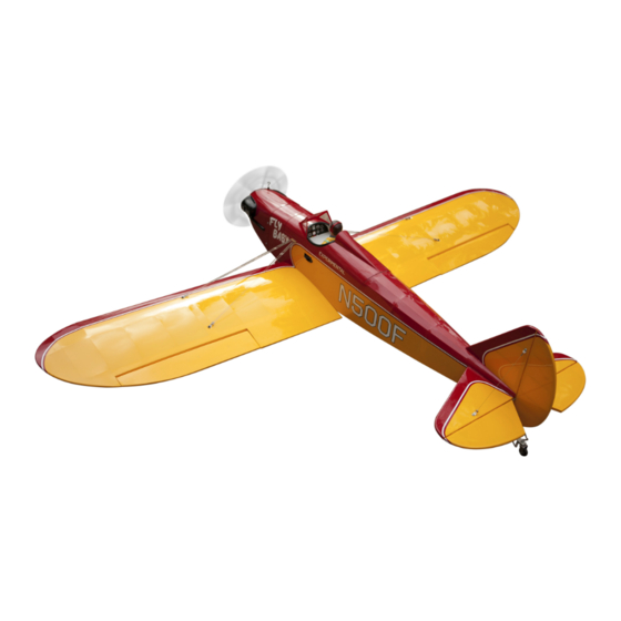
Code: SEA238
" Graphics and specifications may change without notice " .
Specifications:
Wingspan---------------68.9 in (175 cm).
Wing area---------------776.6 sq.in ( 50.1 sq.dm).
Weight-------------------7.7 lbs (3.5 kg).
Length-------------------48.2 in (122.5 cm).
Engine-------------------10cc - 15cc.
Glow engine------------.61 - 2 stroke
Motor size---------------Power 60 ( Electric power)
Radio--------------------4 channels with 5 servos.
Electric conversion: Optional.
www.seagullmodels.com
1
Advertisement
Table of Contents

Related Manuals for Seagull Models SEA238


Summary of Contents for Seagull Models SEA238
- Page 1 WWW.SEAGULLMODELS.COM A S S E M B L Y M A N U A L Code: SEA238 “ Graphics and specifications may change without notice ” . Specifications: Wingspan---------------68.9 in (175 cm). Wing area---------------776.6 sq.in ( 50.1 sq.dm). Weight-------------------7.7 lbs (3.5 kg).
-
Page 2: Kit Contents
Instruction Manual. INTRODUCTION. Thank you for choosing the BOWERS FLYBABY ARF by SEAGULL MODELS COMPANY LTD,. The BOWERS FLYBABY was designed with the intermediate/ad- vanced sport flyer in mind. It is a semi scale airplane which is easy to fly and quick to as- semble. -
Page 3: Hinging The Aileron
WWW.SEAGULLMODELS.COM KIT CONTENTS. HINGING THE AILERON. SEA238 BOWERS FLYBABY Note : The control surfaces, including the ai- SEA23801 Fuselage lerons, elevators, and rudder, are prehinged SEA23802 Wing set with hinges installed, but the hinges are not SEA23803 Tail set glued in place. It is imperative that you prop-... -
Page 4: Hinging The Elevators
Bowers Flybaby Instruction Manual. 4) Deflect the aileron and completely satu- 8) After both ailerons are securely hinged, rate each hinge with thin C/A glue. The ailer- firmly grasp the wing panel and aileron to ons front surface should lightly contact the make sure the hinges are securely glued and wing during this procedure. -
Page 5: Hinging The Rudder
WWW.SEAGULLMODELS.COM INSTALL THE AILERONS CONTROL HORN. Epoxy. Glue the elevator hinges in place using the Fiberglass control horn same techniques used to hing the ailerons. Epoxy. HINGING THE RUDDER. Glue the top two rudder hinges in place using the same techniques used to hinge the ailerons. -
Page 6: Installing Fuselage Servos
Bowers Flybaby Instruction Manual. Epoxy. Rudder fiberglass control horn. INSTALLING THE FUSELAGE SERVOS. Elevator fiberglass control horn. Because the size of servos differ, you may need to adjust the size of the precut opening in the mount. The notch in the sides of the mount allow the servo lead to pass through. - Page 7 WWW.SEAGULLMODELS.COM Loctite secure. Adjustable servo connector. Servo arm. Switch. Throttle servo arm. Rudder servo arm. INSTALLING THE ENGINE SWITCH. Elevator servo arm. Trim and cut. INSTALLING THE RECEIVER SWITCH. Install the switch into the precut hole in the side, in the fuselage. 3/32”...
-
Page 8: Fuel Tank Installation
Bowers Flybaby Instruction Manual. 5) With the stopper assembly in place, the weighted pick-up should rest away from the rear of the tank and move freely inside the tank. The top of the vent tube should rest just below the top of the tank. It should not touch the top of the tank. -
Page 9: Engine Mount Installation
WWW.SEAGULLMODELS.COM Blow through one of the lines to ensure the fuel lines have not become kinked inside the fuel tank compartment. Air should flow through easily. ENGINE MOUNT INSTALLATION. 1) Locate the items necessary to install the engine mount included with your model. - Page 10 Bowers Flybaby Instruction Manual. 145mm Machine screw M4x30mm 4) On the fire wall has the location for the 2) Use a pin drill and 4mm drill bit to throttle pushrod tube (pre-drill). drill a small indentation in the mount for the engine mounting screw.
- Page 11 WWW.SEAGULLMODELS.COM COWLING. Please see below pictures. 8) Reinstall the servo horn by sliding the connector over the pushrod wire. Cent- er the throttle stick and trim and install the servo horn perpendiular to the servo center line. Cut. 9) Move the throttle stick to the closed po- sition and move the carburetor to closed.
- Page 12 Bowers Flybaby Instruction Manual. Because of the size of the cowl, it may be nec- 2) Install the muffler and muffler extension essary to use a needle valve extension for the onto the engine and make the cutout in the high speed needle valve.
- Page 13 WWW.SEAGULLMODELS.COM Blind nut. M3x15mm M4x20mm 4) Attach the motor to the front of the electric motor box using four 4mm blind nut, four M3x12mm hex head bolts to se- cure the motor. Please see picture shown. Epoxy 145 mm Balsa stick. 4 mm Epoxy...
-
Page 14: Installing The Spinner
Bowers Flybaby Instruction Manual. 5) Attach the speed control to the side INSTALLING THE SPINNER. of the motor box using two-sided tape and tie wraps. Connect the appropriate Install the spinner backplate, propeller leads from the speed control to the mo- and spinner cone. - Page 15 WWW.SEAGULLMODELS.COM 4) Apply 2-3 drops of thin C/A to each Servos Small weight of the mounting holes. Allow the C/A to cure without using accelerator. Thread Because the size of servos differ, you may need to adjust the size of the precut opening in the mount.
- Page 16 Bowers Flybaby Instruction Manual. 8) Remove the string from the wing at the servo location and use the tape to attach it to the servo extension lead. Pull the lead through the wing and remove the string. 9) Set the aileron hatch in place and use a Phillips screw driver to install it with four wood screws.
- Page 17 WWW.SEAGULLMODELS.COM AILERON PUSHROD HORN INSTALLATION. Nylon Snap keeper. Please see below pictures. Hex Nut. Fuel tubing. INSTALLING THE MAIN LANDING GEAR TO FUSELAGE. Use a felt tip pen to mark the wire where it crosses the hole. Use a pair of pliers to put a shrp 90-degree bend in the wire at the mark.
- Page 18 Bowers Flybaby Instruction Manual. M4x20mm Collar.
-
Page 19: Installing Wheels
WWW.SEAGULLMODELS.COM INSTALLING WHEELS. Collar. INSTALLING THE HORIZONTAL STABILIZER. 1) Using a ruler and a pen, locate the cen- terline of the horizontal stabilizer, at the trailing edge, and place a mark. Use a tri- angle and extend this mark, from back to front, across the top of the stabilizer. -
Page 20: Installing Vertical Stabilizer
Bowers Flybaby Instruction Manual. 3) Slide the stabilizer into place in the precut slot in the rear of the fuselage. The Epoxy stabilizer should be pushed firmly against the front of the slot. 4) With the stabilizer held firmly in place, use a pen and draw lines onto the stabi- lizer where it and the fuselage sides meet. - Page 21 WWW.SEAGULLMODELS.COM 1) While holding the vertical stabilizer firmly in place, use a pen and draw a line on each side of the vertical stabilizer where it meets the top of the fuselage. 3) Slide the vertical stabilizer into the slot in the top of the fuselage.
-
Page 22: Elevator Pushrod Installation
Bowers Flybaby Instruction Manual. Elevator control horn. 3) Thread one clevis and M2 lock nut on 5) When you are sure that everything is to each elevator control rod. Thread the aligned correctly, mix up a generous horns on until they are flush with the amount of Flash 30 Minute Epoxy. -
Page 23: Rudder Pushrod Installation
WWW.SEAGULLMODELS.COM Pen. Nylon Snap Keeper. RUDDER PUSHROD INSTALLATION. Repeat steps as same as steps done for elevator. M2 lock nut. M2 clevis. - Page 24 Bowers Flybaby Instruction Manual. INSTALL BRACING WIRE AND METAL BRACKET AT THE TAIL. TOP VIEW.
-
Page 25: Mounting The Tail Wheel
WWW.SEAGULLMODELS.COM BOTTOM VIEW MOUNTING THE TAIL WHEEL. Locate items necessary to install tail wheel. 3x25 mm. Aluminum tail landing gear. - Page 26 Bowers Flybaby Instruction Manual. INSTALL FIBERGLASS HORN. M3x10mm Springs Epoxy.
-
Page 27: Apply The Decals
WWW.SEAGULLMODELS.COM 4) Position the canopy onto the fuselage. INSTALLATION PILOT AND CANOPY. Trace around the canopy and onto the fu- selage using a felt-tipped pen. 1) Locate items necessary to install pilot, seats. Epoxy. 2) A scale pilot is included with this ARF. The Seagull Pilot included fitting well to the cockpit. - Page 28 Bowers Flybaby Instruction Manual. INSTALL BRACING WIRE AND METAL BRACKET AT THE WINGS. Battery. Battery. Receiver. ATTACHMENT WING- FUSELAGE. Attach the aluminum tube into fuselage. Wing tube. TOP VIEW. Insert two wing panels as pictures below. Wing bolt.
- Page 29 WWW.SEAGULLMODELS.COM Do the same way with another half wing. BOTTOM VIEW. 29 29...
- Page 30 Bowers Flybaby Instruction Manual. Do the same way with another half wing. Insert canopy hatch on fuselage as pic- tures below.
-
Page 31: Control Throws
WWW.SEAGULLMODELS.COM *If possible, first attempt to balance the BALANCING. model by changing the position of the re- ceiver battery and receiver. If you are un- 1) It is critical that your airplane be able to obtain good balance by doing so, balanced correctly. - Page 32 Bowers Flybaby Instruction Manual. 32 32...
-
Page 33: Flight Preparation
WWW.SEAGULLMODELS.COM FLIGHT PREPARATION. PREFLIGHT CHECK. 1) Completely charge your trans- Check the operation and direction mitter and receiver batteries before of the elevator, rudder, ailerons and your first day of flying. throttle. 2) Check every bolt and every glue A) Plug in your radio system per the joint in the to en- BOWERS FLYBABY...
Need help?
Do you have a question about the SEA238 and is the answer not in the manual?
Questions and answers