Table of Contents
Advertisement
Quick Links
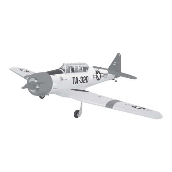
AT 6 - TEXAN
Specifications:
Wingspan----------------------------------------- 62 in------------------------ 158.5cm.
Wing area-------------------------------- 626.5 sq.in------------------- 40.42 sq.dm.
Approximate flying weight-------------6.2-7.7lbs----------------------- 2.8-3.5kg.
Length------------------------------------------- 50.4 in--------------------------- 128cm.
Recommended engine size-------.46-.52 cu.in-------------------------- 2-stroke.
The AT-6 advanced trainer was one of the most widely used aircraft in history. Evolving from
the BC-1 basic combat trainer ordered in 1937, 15,495 Texans were built between 1938 and 1945.
The USAAF procured 10,057 AT-6's, others went to the Navy as SNJ's and to more than 30 Allied
nations. Most AAF fighter pilots trained in AT-6's prior to graduation from flying school. Many of the
"Spitfire" and "Hurricane" pilots in the Battle of Britain trained in Canada in "Harvards," the British
version of the AT-6. To comply with neutrality laws, U.S. built Harvards were flown north to the border
and were pushed across.
In 1948, Texans still in USAF service were redesignated as T-6's when the AT, BT, and PT
aircraft designations were abandoned. To meet an urgent need for close air support of ground forces
in the Korean Conflict, T-6's flew "mosquito missions" spotting enemy troops and guns and marking
them with smoke rockets for attack by fighter-bombers.
The new Seagull Models AT-6 Texan ARF is the perfect standoff scale 40 size sport ARF of
this classic design. Construction is of light ply and balsa built by expert craftsmen and covered in the
classic white, yellow and red color scheme, with a complete decal set. What really sets this AT-6
apart from others is it's prepainted fiberglass cowl, true to scale round fuselage and a completely
prefabricated and hand painted cockpit which includes two instrument panels and two pilots! All of
the hardware that you need can be found in the box also. Fuel tank, wheels, tail wheel assembly,
prebuilt pushrods and more. Even foam rubber to protect your receiver and battery pack is included.
We are sure that you'll agree this is the best built, and the best flying sport scale AT-6 ARF available
anywhere!
------- .72-.82 cu.in----------------------- 4-stroke.
ASSEMBLY MANUAL
Made in Vietnam.
Advertisement
Table of Contents

Related Manuals for Seagull Models AT 6 TEXAN


Summary of Contents for Seagull Models AT 6 TEXAN
- Page 1 The new Seagull Models AT-6 Texan ARF is the perfect standoff scale 40 size sport ARF of this classic design. Construction is of light ply and balsa built by expert craftsmen and covered in the classic white, yellow and red color scheme, with a complete decal set.
-
Page 2: Fuselage Assembly
Instruction Manual. INTRODUCTION. Thank you for choosing the AT 6 - TEXAN ARTF by SEAGULL MODELS. The AT 6 - TEXAN was designed with the intermediate/advanced sport flyer in mind. It is a semi scale airplane which is easy to fly and quick to assemble. The airframe is conventionally built using balsa, plywood to make it stronger than the average ARTF , yet the design allows the aeroplane to be kept light. - Page 3 AT 6 - TEXAN. Instruction Manual. NOTE: To avoid scratching your new aero- plane we suggest that you cover your workbench with an old towel. Keep a couple of jars or bowls handy to hold the small parts after you open the bags.
- Page 4 AT 6 - TEXAN. Instruction Manual. There are 2 options for colour scheme of AT 6: 1. One is standard colours (White and yellow). 2. One is Australia colour scheme (Yellow). With Australia colour scheme for AT 6, you should use black pen (fuel proof) to draw the panel lines on the air plane as same as pictures below: Pen.
- Page 5 AT 6 - TEXAN. Instruction Manual. C/A glue.
-
Page 6: Hinging The Ailerons
AT 6 - TEXAN. Instruction Manual. HINGING THE AILERONS. Note: The control surfaces, including the ailerons, elevators, and rudder, are prehinged with hinges installed, but the hinges are not glued in place. It is imperative that you properly adhere the hinges in place per the steps that follow using a high-quality thin C/A glue. - Page 7 AT 6 - TEXAN. Instruction Manual. 6) Using C/A remover/debonder and a paper towel, remove any excess C/A glue that may have accumulated on the wing or in the aileron hinge area. 7) Repeat this process with the other wing panel, securely hinging the aileron in place.
-
Page 8: Installing The Main Gear Wheels
AT 6 - TEXAN. Instruction Manual. 3mm x 12mm. 6) Reinstall the gear wire and install the straps using the four 3mm x 12mm wood screws. Tighten the screws completely to secure the gear wire in place. Repeat the procedure for the other wing half. - Page 9 AT 6 - TEXAN. Instruction Manual. INSTALLING RETRACTABLE Metal connector. LANDING GEAR ( OPTION II ). Servo arm. Servo for retractable only. Remove covering. Metal clevis. Pre-intalled without glue. M2 clock. Pushrod. 15 mm. 15 mm. Trim and cut. 1mm screw bit. Remove covering.
- Page 10 AT 6 - TEXAN. Instruction Manual. 3mm x 12mm. Trim and cut. Plastic gear cover. C/A glue.
-
Page 11: Wing Assembly
AT 6 - TEXAN. Instruction Manual. WING ASSEMBLY. NOTE: We highly recommend using 30 minute epoxy as it is stronger and provides more working time, allowing the builder to properly align the parts. Using fast cure epoxy when joining the wing halves could result in the glue drying before the wing halves are Epoxy. -
Page 12: Installing The Aileron Servos
AT 6 - TEXAN. Instruction Manual. INSTALLING THE AILERON SERVOS. Thread. Small weight. Servo. We recommended to use long ser- vos arm for all servos without throttle servo. 1) Install the rubber grommets and brass collets onto the aileron servo. Test fit the servo into the aileron servo mount. -
Page 13: Installing The Aileron Linkage
AT 6 - TEXAN. Instruction Manual. Straight line. Plastic tape. 2) Locate the nylon control horns,nylon control horn backplates and two machine screws. 3) Position the aileron horn on the bottom side of aileron. The clevis attachment holes should be positioned over the hinge line. 2) Install the aileron servo mount into the wing, with the output shaft towards the lead- ing edge of the wing. -
Page 14: Installing The Engine Mount
AT 6 - TEXAN. Instruction Manual. Repeat the procedure for the other wing half. Pen. INSTALLING THE ENGINE MOUNT. Mark point. See pictures below: 4mm X 20mm. Cut. FUEL TANK. INSTALLING THE STOPPER ASSEMBLY. 1) Using a modeling knife, carefully cut off M2 lock nut. - Page 15 AT 6 - TEXAN. Instruction Manual. 3) Carefully bend the second nylon tube up 5) With the stopper assembly in place, the at a 45º angle. This tube is the vent tube. weighted pickup should rest away from the rear of the tank and move freely inside the tank. The top of the vent tube should rest just below the top of the tank.
-
Page 16: Mounting The Engine
AT 6 - TEXAN. Instruction Manual. 2) Place your engine onto the engine Vent tube. mount. Adjust the engine is centered of the edges of the engine case. 3) When you are satisfied with the align- ment, mark the locations of the engine mounting. - Page 17 AT 6 - TEXAN. Instruction Manual. 2) While keeping the back edge of the cowl flush with the marks, align the front of the cowl with the crankshaft of the engine. The front of the cowl should be positioned so the crankshaft is in nearly the middle of the cowl opening.
-
Page 18: Installing The Spinner
AT 6 - TEXAN. Instruction Manual. 1.5mm wire (needle valve). 3mmX12mm. INSTALLING THE AIR SCOOP. 1) Using a modeling knife carefully cut out the plastic air scoop along the outside edge of the molded radius. Leave about a 3/32” rim around the perimeter to use as a gluing sur- face. -
Page 19: Installing The Fuselage Servos
AT 6 - TEXAN. Instruction Manual. 4 ) Install the rubber grommets and brass INSTALLING THE FUSELAGE SERVOS. collets onto the elevator, rudder and throttle servos. Test fit the servos into the preinstalled servo tray. Because the size of servos dif- fer, you may need to adjust the size of the precut openings in the tray. -
Page 20: Horizontal Stabilizer
AT 6 - TEXAN. Instruction Manual. 6) Using C/A remover/debonder and a paper towel, remove any excess C/A glue that may have accumulated on the horizontal stabilizer or in the elevator hinge area. 7) Repeat this process with the other horizontal stabilizer panel, securely hinging the elevator in place. -
Page 21: Hinging The Rudder
AT 6 - TEXAN. Instruction Manual. 4) With the stabilizer held firmly in place, use a pen and draw lines onto the stabilizer where it and the fuselage sides meet. Do this on both the right and left sides and top and bottom of the stabilizer. -
Page 22: Vertical Stabilizer Installation
AT 6 - TEXAN. Instruction Manual. VERTICAL STABILIZER INSTALLATION. C/A glue. Hinge. C/A glue. 1) Using a modeling knife, remove the covering from over the precut hinge slot cut into the lower rear portion of the fuselage. This slot accepts the lower rudder hinge. C/A glue. - Page 23 AT 6 - TEXAN. Instruction Manual. 3) While holding the vertical stabilizer firmly in place, use a pen and draw a line on each side of the vertical stabilizer where it meets the top of the fuselage. C/A glue. Pen. 6) Using C/A remover/debonder and a paper towel, remove any excess C/A glue that may have accumulated on the fuselage or in...
-
Page 24: Control Horn Installation
AT 6 - TEXAN. Instruction Manual. CONTROL HORN INSTALLATION. 1) Locate the three nylon control horns, three nylon control horn backplates and four machine screws. 2) Position the elevator horn on the both side of elevator. The clevis attach- ment holes should be positioned over the hinge line. - Page 25 AT 6 - TEXAN. Instruction Manual. MOUNTING THE TAIL WHEEL BRACKET. 1) Set the tail wheel assembly in place on the plywood plate. The pivot point of the tail wheel wire should be even with the rudder hinge line and the tail wheel bracket should be centered on the plywood plate.
-
Page 26: Control Throws
AT 6 - TEXAN. Instruction Manual. MOUNTING THE CONTROL CLASP. 1) Align the tail wheel wire so that the wire is parallel with the bottom of the rudder. The control clasp has a predrilled hole through the top of it. Slide this hole onto the tail wheel wire while sliding the clasp over the bottom of the rudder. -
Page 27: Preflight Check
AT 6 - TEXAN. Instruction Manual. 2) Turn on the radio system, and with the D) Check the throttle. Moving the trim tabs on the transmitter in neutral, center throttle stick forward should open the carbu- the control surfaces by making adjustments retor barrel. - Page 28 When you are about 2-3 feet off the ground, reduce power to idle and gently let the airplane settle onto the runway. Be careful not to over control the airplane. We hope you have enjoyed building and flying your new Seagull Models AT-6 Texan.
Need help?
Do you have a question about the AT 6 TEXAN and is the answer not in the manual?
Questions and answers