Table of Contents
Advertisement
Quick Links
MS:138
ASSEMBLY MANUAL
"Graphics and specifications may change without notice".
Specifications:
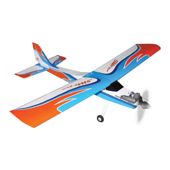
Wing span -------------------------------63in (160cm).
Wing area ------------------643.3sq.in (41.5sq dm).
Weight -------------------------5.5-6.2lbs (2.5-2.8kg).
Length --------------------------------45.8in (116.4cm).
Engine ------------------ 0.40-0.55cu.in ----2 stroke.
0.72-0.82cu.in--- 4 stroke.
Radio------------------------4 channels with 4 servos.
Eletric conversion: optional
Advertisement
Table of Contents

Related Manuals for Seagull Models Swift 40


Summary of Contents for Seagull Models Swift 40
- Page 1 MS:138 ASSEMBLY MANUAL “Graphics and specifications may change without notice”. Specifications: Wing span -------------------------------63in (160cm). Wing area ------------------643.3sq.in (41.5sq dm). Weight -------------------------5.5-6.2lbs (2.5-2.8kg). Length --------------------------------45.8in (116.4cm). Engine ------------------ 0.40-0.55cu.in ----2 stroke. 0.72-0.82cu.in--- 4 stroke. Radio------------------------4 channels with 4 servos. Eletric conversion: optional...
-
Page 2: Fuselage Assembly
SWIFT40. INTRODUCTION. Thank you for choosing the SWIFT40 ARTF by SEAGULL MODELS. The SWIFT 40 was designed with the sports trainer flyer in mind. It is a High-wing aeroplane which is easy to fly and quick to assemble. The airframe is conventionally built using balsa, plywood and veneer to make it stronger than the average ARTF , yet the design allows the aeroplane to be kept light. -
Page 3: Hinging The Ailerons
Instruction Manual. HINGING THE AILERONS. Epoxy. Note: The control surfaces, including the ailerons, elevators, and rudder, are prehinged with hinges installed, but the hinges are not glued in place. It is imperative that you properly adhere the hinges in place per the steps that follow 4) Deflect the aileron and completely using a high-quality thin C/A glue. -
Page 4: Hinging The Elevator
Instruction Manual. SWIFT40. HINGING THE ELEVATOR. Glue the elevator hinges in place using the same techniques used to hinge the ailerons. HINGING THE RUDDER. Glue the rudder hinges in place using the same techniques used to hinge the ailerons. 5) Turn the wing panel over and deflect the aileron in the opposite direction from the opposite side. - Page 5 Instruction Manual. M2x12mm. M2x12mm. INSTALLING THE AILERON SERVO MOUNT. M2x12mm.
-
Page 6: Installing The Aileron Servo
Instruction Manual. SWIFT40. INSTALLING THE AILERON LINKAGE. INSTALLING THE AILERON SERVO. Install the aileron servo into the servo mount, with the output shaft towards the lead- Wire keeper. ing edge of the wing, using the wood screws provided with your radio system. Drill 1/16” pilot holes through the mount before installing the screws. -
Page 7: Nose Gear Installation
Instruction Manual. NOSE GEAR INSTALLATION. M4x20mm. Steering arm. Pushrod wire. FUEL TANK INSTALLATION. M4x20mm. You should mark which tube is the vent and which is the fuel pickup when you attach fuel tubing to the tubes in the stopper. Once the tank is installed inside the fuselage, it may be difficult to determine which is which. -
Page 8: Installing The Fuselage Servos
Instruction Manual. SWIFT40. 3) Connect the lines from the tank to the engine and muffler. The vent line will connect to the muffler and the line from the clunk to the carburetor. 2) Use balsa plywood to help prevent moveable from transferring to the fuel tank as shown. -
Page 9: Mounting The Engine
Instruction Manual. THROTTLE SERVO ARM INSTALLATION. Install adjustable servo connector in the servo arm as same as picture below: Adjustable servo connector. Switch. Loctile Servo arm. secure. MOUNTING THE ENGINE. + ENGENE .46- .55 : 2 STROKE. 1) Position the engine with the drive washer (110mm) forward of the firewall as shown. - Page 10 Instruction Manual. SWIFT40. 2mm. Machine screw M4x30mm. 4) On the fire wall has the location for the throttle pusshrod tube (pre-drill). 8) Reinstall the servo horn by sliding the connector over the pushrod wire. Center the throttle stick and trim and install the servo horn perpendicular to the servo center line.
- Page 11 Instruction Manual. MOUNTING THE ENGINE. + ENGENE .72- .82 : 4 STROKE. 1) Position the engine with the drive washer (120mm) forward of the firewall as shown. 2mm. 5) Slide the pushrod tube in the firewall and guide it through the fuel tank mount. Use 120mm.
- Page 12 Instruction Manual. SWIFT40. 2) Attach the electric motor box to the firewall suitable with the cross lines drawn on the electric motor box and firewall. Using epoxy and balsa stick to secure the motor box to the firewall. Please see pictures below. 9) Move the throttle stick to the closed position and move the carburetor to closed.
- Page 13 Instruction Manual. Blind nut. M4x15mm. Blind nut. M4x70mm. Battery. Speed control.
-
Page 14: Installing The Spinner
Instruction Manual. SWIFT40. 1) Slide the threaded rods from the rudder INSTALLING THE SPINNER. assembly into the holes in the stabilizer. The two forward rods go through the stabilizer as shown. Install the spinner backplate, propeller and spinner cone. The propeller should not touch any part of the spinner cone. -
Page 15: Installation
Instruction Manual. 8mm. M3 lock nut. Elevator control horn. RUDDER PUSHROD HORN ELEVATOR PUSHROD HORN INSTALLATION. INSTALLATION. Control horn. Control horn. Rudder pushrod. Elevator pushrod. Pen. Pen. - Page 16 Instruction Manual. SWIFT40. Receiver. 8mm. Cut. Battery. ATTACHMENT WING-FUSELAGE. INSTALLING THE RECEIVER AND BATTERY. Wing bolt. 1) Plug the five servo leads and the switch lead into the receiver. Plug the battery pack TAIL - DRAGGER CONVERSION. lead into the switch also. M3x12mm.
- Page 17 Instruction Manual. Test fit the fin and the tail gear, to make INSTALLING THE MAIN GEAR WIRES. sure that everything fits properly. When you 1) The blind nuts for securing the landing are happy with the fit, glue the fin permanently gear are already mounted inside the fuselage.
-
Page 18: Control Throws
Instruction Manual. SWIFT40. *If possible, first attempt to balance the model by changing the position of the receiver battery and receiver. If you are unable to obtain good M4x20mm. balance by doing so, then it will be necessary to add weight to the nose or tail to achieve the proper balance point. -
Page 19: Preflight Check
Instruction Manual. 3) Double check the balance of the air- D) Check the rudder. Looking from plane. Do this with the fuel tank empty. behind the airplane, move the rudder stick to the right. The rudder should move to the right. 4) Check the control surfaces.
Need help?
Do you have a question about the Swift 40 and is the answer not in the manual?
Questions and answers