Table of Contents
Advertisement
Quick Links
CHRISTEN
WWW.SEAGULLMODELS.COM
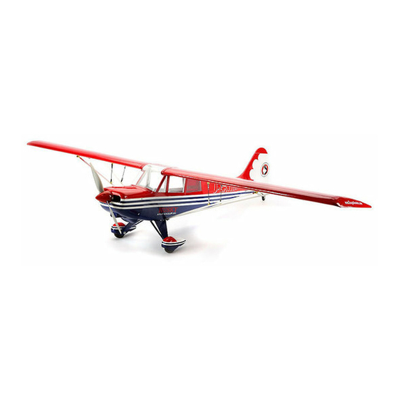
HUSKY
MS: 180
ASSEMBLY MANUAL
"Graphics and specifications may change w ithout notice".
Specifications:
Wingspan---------------79.9 in (203 cm).
Wing area----------------922.3 sq.in (59.5 sq.dm).
Weight-------------------7.9 - 8.8 lbs (3.6 - 4.0 kg).
Length-------------------50.0 in (127.0cm).
Engine-------------------0.61 - 0.75 cu.in----2 stroke.
..........................................- 0.91 cu.in----4 stroke.
Radio--------------------5 channels with 7 servos.
1
Electric conversion: Optional.
Advertisement
Table of Contents

Subscribe to Our Youtube Channel
Related Manuals for Seagull Models CHRISTEN HUSKY SEA180


Summary of Contents for Seagull Models CHRISTEN HUSKY SEA180
- Page 1 CHRISTEN WWW.SEAGULLMODELS.COM HUSKY MS: 180 ASSEMBLY MANUAL “Graphics and specifications may change w ithout notice”. Specifications: Wingspan---------------79.9 in (203 cm). Wing area----------------922.3 sq.in (59.5 sq.dm). Weight-------------------7.9 - 8.8 lbs (3.6 - 4.0 kg). Length-------------------50.0 in (127.0cm). Engine-------------------0.61 - 0.75 cu.in----2 stroke...........- 0.91 cu.in----4 stroke.
-
Page 2: Kit Contents
Instruction Manual. INTRODUCTION. Thank you for choosing the CHRISTEN HUSKY ARTF by SEAGULL MODELS COMPANY LTD,. The CHRISTEN HUSKY was designed with the intermediate/ad- vanced sport flyer in mind. It is a semi scale airplane which is easy to fly and quick to as- semble. -
Page 3: Additional Items Required
WWW.SEAGULLMODELS.COM HINGING THE FLAP KIT CONTENTS. SEA180 CHRISTEN HUSKY 2030mm SEA18001 Fuselage SEA18002 Wing set SEA18003 Tail set SEA18004 Cowling SEA18005 Main Landing Gear SEA18006 Tail Gear SEA18007 Windshield & Window Set SEA18008 Decal Set SEA18009 Linkage Set SEA18010 Wing Tube SEA18011 Fiberglass Wheel pants ADDITIONAL ITEMS REQUIRED. -
Page 4: Hinging The Elevators
CHRISTEN HUSKY Instruction Manual. 3) Remove each hinge from the horizon- tal stabilizer panel and elevator and place a Tpin in the center of each hunge. Slide each hinge into the elevator until the T-pin is snug against the elevator. This will help en- sure an equal amount of hinge is on either side of the hinge line when the elevator is mounted to the horizontal stabilizer panel. -
Page 5: Hinging The Rudder
WWW.SEAGULLMODELS.COM HINGING THE RUDDER. Glue the rudder hinges in place using the same techniques used to hinge the ailer- ons. Epoxy INSTALL THE Fiberglass INSTALL THE AILERONS CONTROL HORN. Fiberglass control horn Epoxy Epoxy... - Page 6 CHRISTEN HUSKY Instruction Manual. INSTALL ELEVATOR CONTROL HORN. Aileron control horn Fiberglass control horn Epoxy INSTALL FLAP CONTROL HORN. Install the flap control horn using the same method as same as the aileron con- trol horns. Fiberglass control horn. Epoxy INSTALL RUDDER CONTROL HORN.
- Page 7 WWW.SEAGULLMODELS.COM wheel collar. Axle. Washer . wheel. Epoxy wheel. wheel collar. Washer . nut. Axle. wheel Pant. C/A glue Epoxy Rudder control WHEEL AND WHEEL PANTS INSTALLING THE MAIN LANDING 1) Assembling and muonting the wheel GEAR TO FUSELAGE pants as shown below pictures. Axle M4x20mm Wheel cover...
-
Page 8: Engine Mount Installation
CHRISTEN HUSKY Instruction Manual. Thread locker glue M4x20 mm Locker glue M4x20mm ENGINE MOUNT INSTALLATION. 1) Locate the items necessary to install the M4x20mm engine mount included with your model. 4x30mm 2) Use four 4x30mm head bolts and four 4mm washers to attach the engine mount INSTALLING WHEEL PANTS TO MAIN rails to the firewall. -
Page 9: Installing The Stopper Assembly
WWW.SEAGULLMODELS.COM Vent tube. Fuel pick up tube. INSTALLING THE STOPPER ASSEMBLY. Fuel fill tube. 1) Using a modeling knife, carefully cut off the rear portion of one of the 3 nylon 3) Carefully bend the second nylon tube tubes leaving 1/2” protruding from the up at a 45º... -
Page 10: Installing The Fuselage Servos
CHRISTEN HUSKY Instruction Manual. Vent tube. Fuel pick up tube. C/A glue Fuel fill tube. 9) Connect the lines from the tank to the engine and muffler. The vent line will con- nect to the muffler and the line from the 7) Slide the fuel tank into the fuselage. -
Page 11: Installing The Switch
WWW.SEAGULLMODELS.COM INSTALLING THE SWITCH. Throttle servo. Install the switch into the precut hole in the side, in the fuselage. 3/32’’ Hole THROTTLE SERVO ARM INSTALLA- TION. Recomend mounting switch inside fuselage if using floats. Install adjustable servo connector in the servo arm as same as picture below: Loctite secure. - Page 12 CHRISTEN HUSKY Instruction Manual. 4) On the fire wall has the location for the throttle pusshrod tube (pre-drill). Pushrod tube hole. 145mm. 2) Use a pin drill and 4mm drill bit to drill a small indentation in the mount for the engine mounting screw.
- Page 13 WWW.SEAGULLMODELS.COM 9) Move the throttle stick to the closed po- sition and move the carburetor to closed. Use a 2.5mm hex wrench to tighten the screw that secures the throttle pushrod wire. Make sure to use threadlock on the screw so it does not vibrate loose. Trim and cut.
-
Page 14: Installing The Aileron - Flap Servos
CHRISTEN HUSKY Instruction Manual. INSTALLING THE AILERON - FLAP SERVOS. 3) Install the muffler and muffler exten- sion onto the engine and make the cutout in the cowl for muffler clearance. Connect the fuel and pressure lines to the carbu- Servos Small weight retor, muffler and fuel filler valve. - Page 15 WWW.SEAGULLMODELS.COM 7) Apply 1-2 drops of thin C/A to each of the mounting tabs. Allow the C/A to cure without using accelerator. C/A glue 3) Use drill bit in a pin vise to drill the mouting holes in the blocks. 8) A string has been provided in the wing to pull the aileron lead through to the wing root.
- Page 16 CHRISTEN HUSKY Instruction Manual. 16 16...
- Page 17 WWW.SEAGULLMODELS.COM Wing M2 lock nut. Aileron 9) Set the aileron hatch in place and use a INSTALLING THE FLAP SERVO. Phillips screw driver to install it with four Repeat the procedure for the aileron wood screws. servo. 50 mm M2 clevis. M2 l o ck nut.
-
Page 18: Installing The Horizontal Stabilizer
CHRISTEN HUSKY Instruction Manual. 4) With the stabilizer held firmly in place, INSTALLING THE HORIZONTAL use a pen and draw lines onto the stabi- STABILIZER. lizer where it and the fuselage sides meet. 1) Using a ruler and a pen, locate the Do this on both the right and left sides centerline of the horizontal stabilizer, at and top and bottom of the stabilizer. -
Page 19: Installing Vertical Stabilizer
WWW.SEAGULLMODELS.COM 7) When you are sure that everything is aligned correctly, mix up a generous Remove covering. amount of 30 Minute Epoxy. Apply a thin layer to the top and bottom of the stabi- lizer mounting area and to the stabilizer mounting platform sides in the fuselage. - Page 20 CHRISTEN HUSKY Instruction Manual. ELEVATOR AND RUDDER PUSHROD HORN INSTALLATION. Rudder control horn Epoxy. 4) When you are sure that everything is aligned correctly, mix up a generous amount of Flash 30 Minute Epoxy. Ap- ply a thin layer to the mounting slot and to bottom of the vertical stabilizer M2 clevis.
- Page 21 WWW.SEAGULLMODELS.COM INSTALLATION TAILWHEEL. 1) Locate the items for this section of the manual. 21 21...
- Page 22 CHRISTEN HUSKY Instruction Manual. 3) Route the antenna in the antenna tube inside the fuselage and secure it to the bottom of fuselage using a plastic tape. 3x25 mm. Recomend Wrapping Receiver in Plastic Bag or Baloon if flying off water. Receiver Aluminum tail landing gear.
-
Page 23: Apply The Decals
WWW.SEAGULLMODELS.COM 1) If all the decals are precut and ready to stick. Please be certain the model is clean and free from oily fingerprints and dust. Position decal on the model where desired, using the photos on the box and aid in their location. 2) If all the decals are not precut, please use scissors or a sharp hobby knife to cut Epoxy... - Page 24 CHRISTEN HUSKY Instruction Manual. M3x15mm. Wing bolt. Screw. M3x15mm. M4x20mm. Screw. INSTALLATION STRUT WING - FUSELAGE. Screw. Epoxy. M3x15mm. 24 24...
- Page 25 WWW.SEAGULLMODELS.COM 4x20mm 4x20mm OPTIONAL FLOAT FOR HUSKY. *Install Structs onto floats. Screw...
- Page 26 CHRISTEN HUSKY Instruction Manual. 3 x 10mm 26 26...
- Page 27 WWW.SEAGULLMODELS.COM C/A glue M2 clevis. M2 lock nut. 600mm. 4 x 20mm 27 27...
- Page 28 CHRISTEN HUSKY Instruction Manual. Accurately mark the balance point on the botttom of the wing on both sides of the fuselage. The balance point is locat- 4 x 20mm ed 80 mm back from the leading edge of the wing at the wing root. This is the bal- ance point at which your model should balance for your first flights.
-
Page 29: Control Throws
WWW.SEAGULLMODELS.COM CONTROL THROWS. 80MM Ailerons: 12mm - 15mm u p 12mm - 15mm down. Elevator: 12mm - 15mm up. 12mm - 15mm down. Rudder: 20mm - 30mm left. 20mm - 30mm right . 29 29... -
Page 30: Flight Preparation
CHRISTEN HUSKY Instruction Manual. FLIGHT PREPARATION. PREFLIGHT CHECK. Check the operation and direction 1) Completely charge your trans- of the elevator, rudder, ailerons and mitter and receiver batteries before throttle. your first day of flying. A) Plug in your radio system per the 2) Check every bolt and every glue manufacturer’s instructions and turn joint in the CHRISTEN HUSKY to... - Page 31 WWW.SEAGULLMODELS.COM FOR USA MARKET ONLY. Safety,Precautions and Warnings As the user of this product, you are solely responsible for operating it in a manner that does not endanger yourself and others or result in damage to the product or the property of others. Carefully follow the direc- tions and warnings for this and any optional support equipment (chargers, rechargeable battery packs, etc.) that you use.
- Page 32 CHRISTEN HUSKY Instruction Manual. If you as the Purchaser or user are not prepared to accept the liability associated with the use of this Product, you are advised to return this Product immediately in new and unused condition to the place of purchase. Law: These Terms are governed by Illinois law (without regard to conflict of law principals).
Need help?
Do you have a question about the CHRISTEN HUSKY SEA180 and is the answer not in the manual?
Questions and answers