Pace ST 65 Operation & Maintenance Manual
Hide thumbs
Also See for ST 65:
- Operation and maintenance manual (20 pages) ,
- Operation and maintenance manual (5 pages)
Table of Contents
Advertisement
Advertisement
Table of Contents

Related Manuals for Pace ST 65


Summary of Contents for Pace ST 65
- Page 1 ST 65 Systems Operation & Maintenance Manual...
- Page 2 Contact your local authorized PACE Distributor or PACE Incorporated to obtain the latest specifications. The following are registered trademarks and/or servicemarks of PACE Incorporated, Laurel Maryland U.S.A. and may only be used to identify genuine PACE products or services: Arm-Evac, Mini-Wave, PACE, SensaTemp, Snap-Vac, Sodrtek, Sodr-X- Tractor, ThermoFlo, ThermoJet, ThermoTweez, Toolnet, Visifilter.
-
Page 3: Table Of Contents
Table of Contents TITLE PAGE General Information ....................2 Introduction ....................2 Specifications ....................2 Parts Identification ..................3 Safety ........................4 Safety Guidelines, English Language .............4 Safety Guidelines, French Language ..............5 Safety Guidelines, German Language .............6 Safety Guidelines, Italian Language ...............7 Safety Guidelines, Portuguese Language ............8 Safety Guidelines, Spanish Language ............9 Safety Guidelines, Swedish Language ............ -
Page 4: General Information
Please read this manual thoroughly before using the system. The ST 65 systems are available in either the 115 VAC, or 230 VAC version which incorporates a highly responsive SensaTemp (closed loop) control system providing up to 80 Watts of total power to a single output channel. -
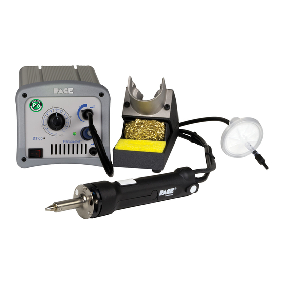
Page 5: Parts Identification
General Information Parts Identification Power Receptacle Controllable Pressure Port AC Power Receptacle/Fuse Holder Fuse Variable Temperature Control Earth Ground Receptacle Power Switch (230 VAC Systems only) Air Hose Fitting Vacuum Port... -
Page 6: Safety
Be sure to place the handpiece in its holder after use and allow to cool before storing. 5. Always use PACE systems in a well ventilated area. A fume extraction system such as those available from PACE are highly recommended to help protect personnel from solder flux fumes. -
Page 7: Safety Guidelines, French Language
Des brûlures sévères peuvent en résulter. 4. Les outils PACE et leurs pannes ainsi que le support sont dessinés de manière spécifique afin de protéger l'utilisateur/opérateur de brûlures accidentelles. Reposer toujours les outils après chaque utilisation dans leurs étuis/supports afin de permettre leur refroidissement. -
Page 8: Safety Guidelines, German Language
Loetspitzen sind heiss wenn das System eingeschaltet ist oder erst vor kurzer Zeit ausgeschaltet wurde. Heizelement und Loetspitze nicht beruehren. Verbrennungsgefahr. 4. PACE Tip & Tool und andere Handwerkzeugablagen sind so konstruiert, dass ein versehentliches Beruehren des dazugehoerendes Handwerkzeuges vermieden wird. Bewahren Sie das Handwerkzeug nach Gebrauch stets in der Ablage auf. -
Page 9: Safety Guidelines, Italian Language
Mettere sempre l’impugnatura nel propio supporto dopo l’utilizzo e lasciarla raffredare prima di riporla. 5. Utilizzare sempre I stazioni PACE in una zona be aerata per proteggere il personale dai fumi. É fortemente raccomandato un sistema di aspirazione (dei fumi) come quello disposta dalla PACE. -
Page 10: Safety Guidelines, Portuguese Language
5. Utilize sempre os sistemas da PACE em locais bem ventilados. Um Sistema de extracção de fumos, como os Sistemas disponiveis na PACE, são altamente recomendados para a protecção dos utilizadores contra os fumos produzidos pela... -
Page 11: Safety Guidelines, Spanish Language
5. Siempre use sistemas de PACE en una área bien ventilada. Un sistema de extraccíon de humo como esos disponibles de PACE se recomiendan para ayudar a protejer al personal contra los humos de flujo de soldadura. -
Page 12: Safety Guidelines, Swedish Language
Följande säkerhetsföreskrifter måste förstås och följas av personal som använder eller utför service på PACE produkter. 1. RISK FÖR STRÖMSTÖT - Service / Reparation av PACE produkter får endast utföras av aktoriserad service personal. Strömförande delar kan kommas åt när produkten är isärplockad. Iaktag aksamhet när felsökning görs för att undvika strömstötar. -
Page 13: Set-Up
Set-Up Set-up Set up the ST 65 system using the following steps and associated drawings. 1. Store the shipping container(s) in a convenient location. Reuse of these containers will prevent damage if you store or ship the system. 2. Place the Power Switch in the “OFF” or “0”... -
Page 14: Tip & Tool Stand
Set-Up Tip & Tool Stand If you have purchased a system with a handpiece, set up the Tip & Tool Stand in the following manner. If you have purchased another SensaTemp handpiece, use the instructions enclosed with the handpiece and associated Tip & Tool Stand. 1. -
Page 15: Air Supply Connection
Set-Up Air Supply Connection The ST 65 system utilizes an integral air venturi system to provide air pressure and vacuum for any connected PACE SensaTemp air handpiece. Your in-house air supply (regulated to 5.48 Bar (80 P.S.I.); see "Specifications") must be connected to the system power source. -
Page 16: Handpiece Vacuum/Pressure
6 inches from the ends of the handpiece. c) If you have a PACE system incorporating 2 or more air handpieces, you may wish to leave the air hose assembly unattached to allow a quick change to any air handpiece being used. -
Page 17: Handpiece Connection
Set-Up b) Connect the free end of a 1 inch (2.5cm) length of air hose with an installed female quick connect hose mount fitting (P/N 1259-0086) to the FLOW IN side of the VisiFilter Assembly. c) The 137cm (54 inch) length of air hose can now be easily moved between the VisiFilter Assembly and the Controllable Pressure Port. -
Page 18: Handpiece Heater Burn In
A Red tag is attached to the handpiece and with replacement heater assemblies. Follow the Burn In procedure listed on the tag when setting up a new ST 65 system or when replacing a handpiece heater assembly. -
Page 19: Led Operation
SMT soldering tips. This difference is called Tip Temperature Offset. PACE recommends the use of the Tip & Temperature Selection System booklet (PACE P/N 5050-0251) as a guide to accurately set and maintain a true tip temperature for any size and type of SMT tip. -
Page 20: Calibration
Calibration The ST 65 system is tested for temperature accuracy at the factory and can be checked for calibration according to PACE requirements. Also, a temperature setting normally used by the operator can be adjusted to the precise temperature indicated on the Dial/Display. -
Page 21: Corrective Maintenance
Corrective Maintenance Power Source Most malfunctions are simple and easy to correct. Refer to Table 1 below to clear these malfunctions. Symptom Probable Cause Solution No power to system. Blown Fuse Check handpiece using Table 2. Replace the fuse (located in the AC Receptacle/Fuse Holder) with one of same value (see Table 4, Spare Parts). -
Page 22: Handpieces
Handpieces The following “Heater Assembly Checkout Procedures” (Table 4) is applicable to all PACE SensaTemp handpieces used with the ST 85 system except for the TT- 65 and DTP-80 handpieces. Refer to the applicable manuals for troubleshooting procedures pertinent to that handpiece. -
Page 23: Packing List/Spare Parts
Operation & Maintenance Manual 5050-0454 Table 3. Packing List Spare Parts Item Description Part Number 1.0 A mp Time Lag (ST 65) 1159-0246 Fuse, 0.5 Amp Time Lag (ST 65E ) 1159-0213 Replacement PCB Assembly 6 020-0125-P - Tip & Temperature S election System Booklet. -
Page 24: Limited Warranty Form
LIMITED W ARRANTY PACE warrants that this equipm ent will be free of defects in m aterials and workm anship for a period of one (1) year from the date of receipt by the first user. This warranty does not cover repair or replacem ent required as a result of m isuse, m ishandling or im proper storage.
Need help?
Do you have a question about the ST 65 and is the answer not in the manual?
Questions and answers