
Related Manuals for Pace SODRTEK ST 325


Summary of Contents for Pace SODRTEK ST 325
- Page 1 Operation and Maintenance Manual for the ® SODRTEK ST 325 Digital Convective Soldering/Desoldering System P/N 5050-0537...
-
Page 2: Table Of Contents
Preheating ......................27 Corrective Maintenance ....................28 Display Error Messages ..................28 Power Source/Handpiece..................28 Packing List ........................29 Spare Parts ........................29 Service ..........................29 “SODRTEK by PACE” LIMITED WARRANTY STATEMENT ........30 Contact Us........................31 ©2013 PACE Inc., Southern Pines, NC Page 2 of 31 All Rights Reserved... -
Page 3: General Information
General Information Introduction ® Thank you for purchasing the PACE SODRTEK model ST 325 Analog Convective Soldering/Desoldering System. This manual will provide you with the information necessary to properly set up, operate, and maintain the ST 325. Please read this manual thoroughly before using the unit. -
Page 4: Parts Identification
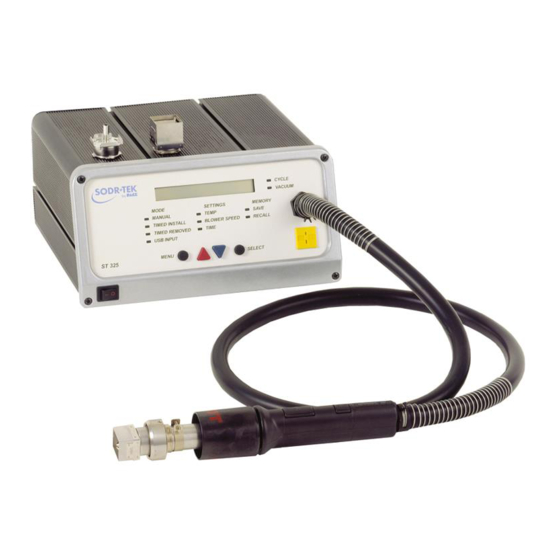
Select Key Switch LoFlo Vacuum Scroll Keys Port RS 232 PC Input Fuse Fuse Remote Controller Receptacle Pre-Heater Receptacle AC Power Receptacle Earth Ground Receptacle (ST 450) ©2013 PACE Inc., Southern Pines, NC Page 4 of 31 All Rights Reserved... - Page 5 VACUUM PICK ASSEMBLY - Provides a means to lift or place components. VACUUM CUP - Provides positive holding of components for positioning during the replacement process and for lifting of the component during the removal process. ©2013 PACE Inc., Southern Pines, NC Page 5 of 31 All Rights Reserved...
-
Page 6: Safety
Severe burns may result! 2. Utilize all standard electrical safety precautions when using this or any other electrical equipment. ©2013 PACE Inc., Southern Pines, NC Page 6 of 31 All Rights Reserved... -
Page 7: Servicing Precautions
4. Always use this system in a well-ventilated area. A fume extraction system such as those available from PACE are highly recommended to protect personnel from solder flux fumes. 4. Exercise proper precautions when using chemicals (e.g., solder paste). Refer to the Material Safety Data Sheet (MSDS) supplied with each chemical and adhere to all safety precautions recommended by the manufacturer. -
Page 8: Vacuum Pick
QuickFit Nozzle Adapter The ST 325 QuickFit Adapter allows you to easily change out any PACE ST 325 Nozzle. Attach the adapter to the handpiece heater using the following instructions. 1. Insert the QuickFit Adapter into the end of the handpiece heater as shown. -
Page 9: Nozzle Selection
The cup selected should be as large as possible without exceeding the body size of the component. Vacuum cups are consumable items which deteriorate over a period of time. ©2013 PACE Inc., Southern Pines, NC Page 9 of 31 All Rights Reserved... -
Page 10: Nozzle Changeout
Set-Up Mode: Mode of operation in which the operator can quickly and easily enter, change or delete system parameters (e.g., password, ° C/° F display, profile deletion). ©2013 PACE Inc., Southern Pines, NC Page 10 of 31 All Rights Reserved... -
Page 11: System Power Up
NOTE: Please copy the chosen password and keep in a safe place. 6. Press the Select Button after the password is selected. The LCD will now display the desired temperature scale (e.g., “Display is ° F?”). ©2013 PACE Inc., Southern Pines, NC Page 11 of 31 All Rights Reserved... -
Page 12: Automatic Calibration
The ST 325 System provides precision control of temperature thanks to the closed-loop controlled circuit design. The temperature sensor is located in the heater but utilizing the PACE Thermocouple Nozzle can yield more accurate results due to moving the temperature sensor closer to the component. The Automatic Calibration Procedure allows the system to calibrate for various style components as well as to adjust for any minor offsets in temperature due to heater differences and blower speeds. -
Page 13: Operation
NOTE: If during the procedure the LCD displays “ Auto Cal Error,” repeat the Auto Calibration Procedure again. Operation The PACE ST 325 unit is easy to operate and can be quickly set up for operation. The following steps provide basic guidelines for rework using the PACE ST 325. Password The Password feature of the ST 325 system, when activated, will prevent unauthorized alteration of stored system temperature parameters and custom settings (refer to the “Set Up Mode Section”). -
Page 14: Pik-Vak Operation
4. Press the Menu button once. This will toggle you to the Settings column. The LCD screen will display the temperature and the Temp LED will be flashing. 5. Press the Select Button once. ©2013 PACE Inc., Southern Pines, NC Page 14 of 31 All Rights Reserved... - Page 15 17. Position the nozzle (with component) over a heat resistant surface. 18. Press and hold the Vacuum Cycle Switch for 0.5 second (minimum) to deactivate vacuum and release component. ©2013 PACE Inc., Southern Pines, NC Page 15 of 31 All Rights Reserved...
-
Page 16: Component Installation; Manual Mode
BGA components will rest against the walls of the nozzle. When using Pattern nozzles, position component leads beneath and in line with the air jets on the nozzle. ©2013 PACE Inc., Southern Pines, NC Page 16 of 31 All Rights Reserved... - Page 17 17. If using a Single Jet nozzle in a hand held operation, move the handpiece as necessary to direct air flow to the solder areas requiring reflow. ©2013 PACE Inc., Southern Pines, NC Page 17 of 31 All Rights Reserved...
-
Page 18: Timed Removal
12. Adjust the vacuum cup to a point where the bottom of the vacuum cup is approximately flush with the bottom edge of the nozzle using the Vacuum Pick Adjust Control. 13. Hold the handpiece vertical to the PCB. ©2013 PACE Inc., Southern Pines, NC Page 18 of 31 All Rights Reserved... -
Page 19: Timed Install
2. Set the unit POWER Switch (on front panel of power source) to the ON position. 3. Use the Scroll Keys ( ) to select the Timed Install LED. ©2013 PACE Inc., Southern Pines, NC Page 19 of 31 All Rights Reserved... - Page 20 12. Using the Vacuum Pick Adjust Control, adjust the vacuum cup to a point where the bottom of the cup is flush with the bottom edge of the nozzle. 13. Press the Vacuum Pick Switch to activate vacuum. ©2013 PACE Inc., Southern Pines, NC Page 20 of 31 All Rights Reserved...
- Page 21 15. Using the Vacuum Pick Adjust Control, adjust the height of the component relative to the nozzle as desired. PACE recommends that: a) The bottom of the nozzle should be positioned approximately 1mm (0.040") above the PCB when using Box or Pattern nozzles.
-
Page 22: Pc Control
4. Press the Select Button once to save the profile. Recall The following procedure will step you through the profile Recall procedure in the Memory Column. This can be accessed through the Install or Removed Mode. ©2013 PACE Inc., Southern Pines, NC Page 22 of 31 All Rights Reserved... -
Page 23: Process Development
(in Program Mode). Up to 20 user-defined profiles may be stored in microprocessor memory. NOTE: When developing Profiles, PACE recommends the use of embedded thermocouples on a test board to ensure optimum process results. Profile Development 1. -
Page 24: Profile Development
Pattern Nozzle Temperature Install (° C) Blower Speed Temperature Remove (° C) Appropriate Size Blower Speed Chip Component Single Jet Nozzle Temperature Install (° C) Blower Speed ©2013 PACE Inc., Southern Pines, NC Page 24 of 31 All Rights Reserved... - Page 25 (sec.) Blower Speed Reflow Temp. Time (sec.) Blower Speed (Install Only) Vacuum Release Lower Pump Cool Down Approved By: Time (sec.) Date: Blower Speed Comments / Instructions: ©2013 PACE Inc., Southern Pines, NC Page 25 of 31 All Rights Reserved...
-
Page 26: General Process Guidelines
If too much paste is applied, solder bridges will form between the lands. If an insufficient amount of paste is applied, solder joint formation will be ©2013 PACE Inc., Southern Pines, NC Page 26 of 31... -
Page 27: Component Positioning
(in accordance with your company requirements) after solder paste deposition to remove any volatiles (e.g., solvents) in the paste. The PACE ST 400 & ST 450 systems are highly recommended for this preheating application. Preheating can also be accomplished with top heat. -
Page 28: Corrective Maintenance
Display on Digital Refer to Display Error Messages. Readout indicates a malfunction. Little or no vacuum Worn vacuum Replace vacuum pump. Contact PACE for pump assistance. Vacuum Cup will not Worn or broken Replace vacuum cup. hold component... -
Page 29: Packing List
Fuse, 5 Amp, 250 V, Fast Acting (ST 325E) 1159-0266-P5 Fuse, 0.5 Amp, 250 V, Time Lag 1159-0213-P5 Optional PC Control Software 1199-0019-P1 Service Please contact PACE or your local distributor for service and repair. ©2013 PACE Inc., Southern Pines, NC Page 29 of 31 All Rights Reserved... -
Page 30: Sodrtek By Pace" Limited Warranty Statement
Warranty service may be obtained by contacting the appropriate PACE Company or local Authorized PACE distributor as set forth below to determine if return of any item is required, or if repairs can be made by the user in the field. Any warranty or other claim with respect to the products must be made with sufficient evidence of purchase and date of receipt, otherwise user’s rights under this warranty shall be... -
Page 31: Contact Us
PACE Incorporated retains the right to make changes to specifications contained herein at any time, without notice. Contact your local authorized PACE Distributor or PACE Incorporated to obtain the latest specifications. The following are trademarks and/or service marks of PACE, Incorporated, MD, USA: ™...
Need help?
Do you have a question about the SODRTEK ST 325 and is the answer not in the manual?
Questions and answers