
Related Manuals for Pace SODRTEK ST 300


Summary of Contents for Pace SODRTEK ST 300
- Page 1 Operation and Maintenance Manual for the ® SODRTEK ST 300 Analog Convective Soldering/Desoldering System P/N 5050-0536...
-
Page 2: Table Of Contents
Handpiece Vacuum/Pressure................9 Component Removal .................... 9 Component Installation ..................10 PikVac Operation ....................11 Corrective Maintenance ....................12 Packing List ........................13 Spare Parts ........................13 Service ..........................13 Contact Information ....................... 14 ©2004 PACE Inc., Annapolis Junction, Maryland All Rights Reserved... -
Page 3: General Information
General Information Introduction ® Thank you for purchasing the PACE SODRTEK model ST 300 Analog Convective Soldering/Desoldering System. This manual will provide you with the information necessary to properly set up, operate and maintain the ST 300. Please read this manual thoroughly before using the unit. The ST 300 system is a complete system designed for hot air removal and installation of SMD components, including Ball Grid Arrays (BGAs). -
Page 4: Parts Identification
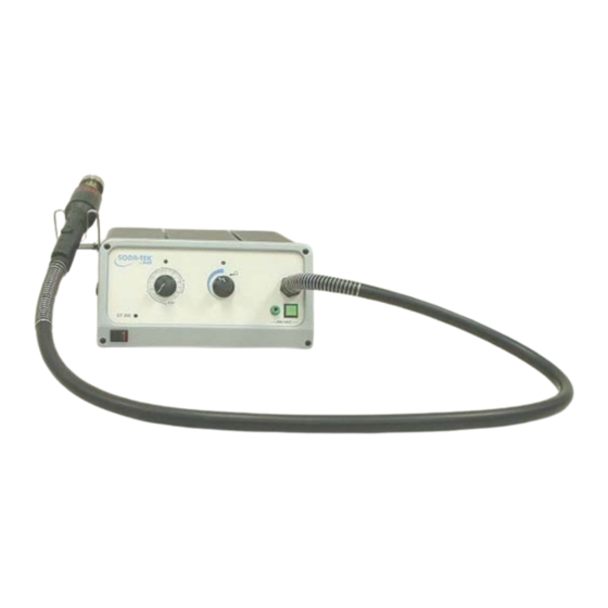
Variable Temperature Variable Blower Temp LED Blower LED Selection Knob Speed Knob Handpiece Power Switch Power On LED LoFlo Vacuum Port Illuminated LoFlo Pump Switch Earth Ground Receptacle Fuses AC Power Receptacle ©2004 PACE Inc., Annapolis Junction, Maryland All Rights Reserved... -
Page 5: Safety
2. Always use the handpiece with the Heat Shield installed except when the handpiece is mounted to its work platform. The Heat Shield helps to prevent unintentional contact with the heater. ©2004 PACE Inc., Annapolis Junction, Maryland All Rights Reserved... -
Page 6: Servicing Precautions
4. Always use this system in a well-ventilated area. A fume extraction system such as those available from PACE are highly recommended to protect personnel from solder flux fumes. 5. Exercise proper precautions when using chemicals (e.g., solder paste). Refer to the Material Safety Data Sheet (MSDS) supplied with each chemical and adhere to all safety precautions recommended by the manufacturer. -
Page 7: Tip & Tool Stand
1. While holding the Rubber Pad, gently twist the nozzle as shown. The nozzle will easily release from the Nozzle Adapter. 2. Place the nozzle (still hot) on a heat resistant surface. ©2004 PACE Inc., Annapolis Junction, Maryland All Rights Reserved... -
Page 8: Installation
(see Corrective Maintenance section). Variable Airflow Control Adjust the Variable Airflow Control Knob to the desired airflow setting. NOTE: The Variable Airflow Control LED will be illuminated whenever the ST 300 blower is running. ©2004 PACE Inc., Annapolis Junction, Maryland All Rights Reserved... -
Page 9: Handpiece Vacuum/Pressure
PCB; steps 13 & 14 are not used. 13. Position the nozzle (with component) over a heat resistant surface. 14. Press and hold the Vacuum Pick Switch for 0.5 second (minimum) to deactivate vacuum and release component. ©2004 PACE Inc., Annapolis Junction, Maryland All Rights Reserved... -
Page 10: Component Installation
To contact a BGA component when using a V-A-N nozzle. 10. Lower nozzle (with component) to a point where the component leads/contacts rest gently on or just above the component land pattern. ©2004 PACE Inc., Annapolis Junction, Maryland All Rights Reserved... -
Page 11: Pikvac Operation
NOTE: If component has been prepositioned on land pattern, lower nozzle to desired height above PCB. A height of 1-1.5mm (.040-.060") above the PCB when using Box or Pattern nozzles is recommended. 11. Ensure that the handpiece is held vertical to the PCB (except with Single Jet nozzles). 12. -
Page 12: Corrective Maintenance
Change routing of air hose to remove heater heats and kinks blower is running Little or no vacuum Worn vacuum Replace vacuum pump. Contact PACE for pump assistance. Vacuum Cup will not Worn or broken Replace vacuum cup hold component... -
Page 13: Packing List
Fuse, 7A, 125 V, Fast Acting (ST 300) 1159-0274-P5 Fuse, 5A, 230 V, Fast Acting (ST 300E) 1159-0266-P5 Fuse, 0.5A, Time Lag 1159-0213-P5 Service Please contact PACE or your local distributor for service and repair. ©2004 PACE Inc., Annapolis Junction, Maryland All Rights Reserved... -
Page 14: Contact Information
PACE Incorporated retains the right to make changes to specifications contained herein at any time, without notice. Contact your local authorized PACE Distributor or PACE Incorporated to obtain the latest specifications. The following are trademarks and/or service marks of PACE, Incorporated, MD, USA: ™...
Need help?
Do you have a question about the SODRTEK ST 300 and is the answer not in the manual?
Questions and answers