
Related Manuals for Pace Sodrtek ST 125


Summary of Contents for Pace Sodrtek ST 125
- Page 1 Operation and Maintenance Manual for the ® SODRTEK ST 125 Soldering System P/N 5050-0534...
-
Page 2: Table Of Contents
Vacuum Pump Operation ..................9 Handpiece Vacuum Pressure..................9 Corrective Maintenance ....................10 Power Source ......................10 Handpieces......................10 Packing List........................11 Spare Parts ........................11 Service ..........................11 “SODRTEK by PACE” LIMITED WARRANTY STATEMENT........12 Contact Information.......................13 ©2004 PACE Inc., Annapolis Junction, Maryland Page 2 of 13 All Rights Reserved... -
Page 3: General Information
General Information Introduction ® Thank you for purchasing the PACE SODRTEK model ST 125 Analog Desoldering System. This manual will provide you with the information necessary to properly set up, operate and maintain the ST 125. The ST 125 system is available in either 115 VAC or 230 VAC versions, which incorporates a highly responsive SensaTemp (closed loop) control system providing up to 80 Watts of total power to a single output channel. -
Page 4: Parts Identification
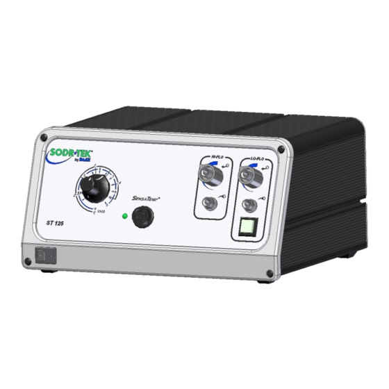
LoFlo Pressure Port Power Switch LoFlo Vacuum Port Illuminated LoFlo Pump Switch Front Panel LED HiFlo Vacuum Port Earth Ground Receptacle TEKLINK Receptacle AC Power Receptacle/Fuse Holder Fuse ©2004 PACE Inc., Annapolis Junction, Maryland Page 4 of 13 All Rights Reserved... -
Page 5: Safety Guidelines
Always store the handpiece in its holder. Be sure to place the handpiece in its holder after use and allow for cooling before storing. 5. Always use PACE systems in a well ventilated area. A fume extraction system such as those available from PACE are highly recommended to help protect personnel from solder flux fumes. -
Page 6: System Set-Up
ST 125/145 system. 2. Use the TEKLINK cable (sold separately) to connect the systems together. The TEKLINK Receptacle is located on the back panel of each power supply. ©2004 PACE Inc., Annapolis Junction, Maryland Page 6 of 13 All Rights Reserved... -
Page 7: System Power Up
Thru-Hole, single point soldering tips. With any heating system however, True Tip Temperatures can differ greatly from temperature settings when using larger SMT soldering tips. This difference is called Tip Temperature Offset. PACE recommends the use of the Tip & Temperature Selection ©2004 PACE Inc., Annapolis Junction, Maryland... -
Page 8: Variable Temperature Control
System booklet (PACE P/N 5050-0251) as a guide to accurately set and maintain a true tip temperature for any size and type of SMT tip. Variable Temperature Control Adjust the Variable Temperature Control Knob to the desired temperature setting. Notice that the control panel has an outer graphic scale denoting temperature in °C (Celsius) and an inner graphic scale denoting temperature in... -
Page 9: Vacuum Pump Operation
PACE factory specifications) or the temperature setting normally used by the operator. If the temperature displayed on temperature meter is within ±15°C (27°F), perform steps 4 thru 6 to obtain a precise reading. If the temperature is off by more than ±15°C, the handpiece may require maintenance. -
Page 10: Corrective Maintenance
Insert the end of the quick connect hose mount fitting (on VisiFilter FLOW OUT side) into the power source Vacuum Port. 3. When using air pressure, and/or utilizing multiple air handpieces, PACE recommends the use of the following set up procedure which utilizes additional quick connect hose mount fittings. -
Page 11: Handpieces
Fuse, 0.63 Amp, 250 V, Time Lag (ST 125E) 1159-0252-P5 Tip & Temperature Selection Chart 5050-0251 TEKLINK Cable 1332-0252-P1 TEKLINK Remote Box 3008-0218-P1 Service Please contact PACE or your local distributor for service and repair. ©2004 PACE Inc., Annapolis Junction, Maryland Page 11 of 13 All Rights Reserved... -
Page 12: Sodrtek By Pace" Limited Warranty Statement
Warranty service may be obtained by contacting the appropriate PACE Company or local Authorized PACE distributor as set forth below to determine if return of any item is required, or if repairs can be made by the user in the field. Any warranty or other claim with respect to the products must be made with sufficient evidence of purchase and date of receipt, otherwise user’s rights under this warranty shall be... -
Page 13: Contact Information
PACE Incorporated retains the right to make changes to specifications contained herein at any time, without notice. Contact your local authorized PACE Distributor or PACE Incorporated to obtain the latest specifications. The following are trademarks and/or service marks of PACE, Incorporated, MD, USA: ™...
Need help?
Do you have a question about the Sodrtek ST 125 and is the answer not in the manual?
Questions and answers