Pace ST 25 Operation And Maintenance Manual
St 25 soldering system sodrtek
Hide thumbs
Also See for ST 25:
- Operation and maintenance manual (14 pages) ,
- Operation and maintenance manual (11 pages)

Related Manuals for Pace ST 25


Summary of Contents for Pace ST 25
- Page 1 Operation and Maintenance Manual for the ® SODRTEK ST 25 Soldering System P/N 5050-0530...
-
Page 2: Table Of Contents
TEKLINK ........................7 Temperature Dial Adjustment ..................8 Corrective Maintenance Power Source .......................8 Handpieces......................9 Packing List........................9 Spare Parts ........................9 Service ..........................10 “SODRTEK by PACE” LIMITED WARRANTY STATEMENT........10 Contact Information.......................11 ©2004 PACE Inc., Annapolis Junction, Maryland Page 2 of 11 All Rights Reserved... -
Page 3: General Information
ST 25. The ST 25 system is available in either 115 VAC or 230 VAC versions, which incorporates a highly responsive SensaTemp (closed loop) control system providing up to 80 Watts of total power to a single output channel. -
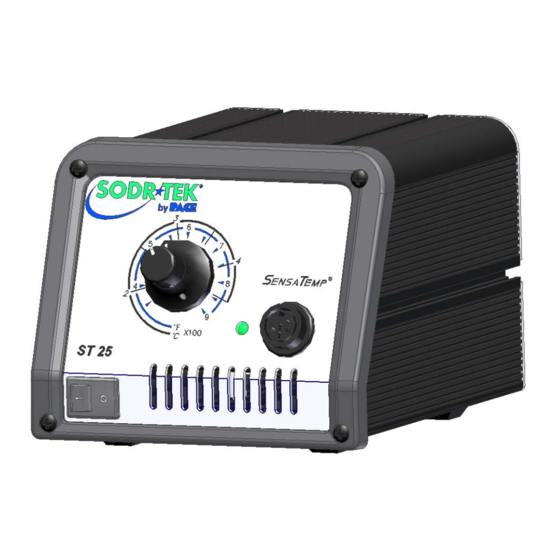
Page 4: Parts Identification
Parts Identification Power Receptacle Temperature Selection Dial Power Switch Front Panel LED TEKLINK Receptacle Earth Ground Receptacle AC Power Receptacle/Fuse Holder Fuse ©2004 PACE Inc., Annapolis Junction, Maryland Page 4 of 11 All Rights Reserved... -
Page 5: Safety
2. Place the Power Switch in the “OFF” or “0” position. Mounting Options The ST 25 can be placed directly on a workbench or it also can also be mounted under a workbench or shelf to conserve space (optional mounting bracket sold separately). To mount the system in this way (ST 45 shown): 1. -
Page 6: Tip & Tool Stand
The Tip & Tool Stand can be mounted to the power source. If the system will be placed on the workbench, this is recommended. If the ST 25 is to be mounted under the workbench or shelf, the Tip & Tool Stand should not be mounted to the power source. -
Page 7: Operation
VACUUM and PRESSURE ports of the ST 125/145. To link your ST 25 system to the ST 125/145 system, perform the following procedure. Place your ST 25/45 system adjacent to (side by side) or stacked on top of the ST 125/145 system. -
Page 8: Temperature Dial Adjustment
The TEKLINK Remote Box (sold separately) allows the connection of up to three ST 25/45 systems in any combination. NOTE: Systems connected together through the TEKLINK system must be used and controlled by a single operator. Any attempt to operate by more than one individual can create a hazard condition and will cause deterioration in performance. -
Page 9: Handpieces
TEKLINK Cable 1332-0252-P1 TEKLINK Remote Box 3008-0218-P1 Optional Under Workbench Mounting Bracket 1321-0609-P1 Spare Parts Service Please contact PACE or your local distributor for service and repair. ©2004 PACE Inc., Annapolis Junction, Maryland Page 9 of 11 All Rights Reserved... -
Page 10: Sodrtek By Pace" Limited Warranty Statement
Warranty service may be obtained by contacting the appropriate PACE Company or local Authorized PACE distributor as set forth below to determine if return of any item is required, or if repairs can be made by the user in the field. Any warranty or other claim with respect to the products must be made with sufficient evidence of purchase and date of receipt, otherwise user’s rights under this warranty shall be... -
Page 11: Contact Information
PACE Incorporated retains the right to make changes to specifications contained herein at any time, without notice. Contact your local authorized PACE Distributor or PACE Incorporated to obtain the latest specifications. The following are trademarks and/or service marks of PACE, Incorporated, MD, USA: ™...
Need help?
Do you have a question about the ST 25 and is the answer not in the manual?
Questions and answers