Pace SODRTEK ST 25 Operation And Maintenance Manual
Soldering system
Hide thumbs
Also See for SODRTEK ST 25:
- Operation and maintenance manual (11 pages) ,
- Operation and maintenance manual (14 pages)

Related Manuals for Pace SODRTEK ST 25


Summary of Contents for Pace SODRTEK ST 25
- Page 1 Operation and Maintenance Manual for the ® SODRTEK ST 25 Soldering System P/N 5050-0530 w w w . e k t . c o m...
-
Page 2: Table Of Contents
Temperature Dial Lock ..................7 LED Operation......................7 Temperature Dial Adjustment ..................8 Corrective Maintenance Power Source .......................8 Handpieces......................9 Packing List........................9 Spare Parts ........................9 Service ..........................10 PACE LIMITED WARRANTY STATEMENT..............10 Contact Information.......................11 w w w . e k t . c o m... -
Page 3: General Information
General Information Introduction The ST 25 system is available in either 115 VAC or 230 VAC versions, which incorporates a highly responsive SensaTemp (closed loop) control system providing up to 80 Watts of total power to a single output channel. The 230 VAC version system bears the CE Conformity Marking, which assures the user that it conforms to EMC 89/336/EEC. -
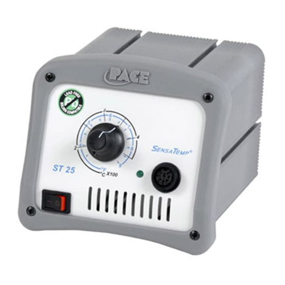
Page 4: Parts Identification
Parts Identification Power Receptacle Temperature Selection Dial Power Switch Front Panel LED Earth Ground Receptacle AC Power Receptacle Fuse Holder w w w . e k t . c o m... -
Page 5: Safety
5. Always use PACE systems in a well ventilated area. A fume extraction system such as those available from PACE are highly recommended to help protect personnel from solder flux fumes. -
Page 6: Tip & Tool Stand
Tip & Tool Stand The Tip & Tool Stand can be mounted to the power source. If the system will be placed on the workbench, this is recommended. If the ST 25 is to be mounted under the workbench or shelf, the Tip &... -
Page 7: Operation
The ST 25 system is tested for temperature accuracy at the factory and can be checked for calibration according to PACE requirements. Also, a temperature setting normally used by the operator can be adjusted to the precise temperature indicated on the Dial/Display. -
Page 8: Corrective Maintenance
1100-0307 Operations Manual CD CD5050-0459 Packing List Spare Parts Item # Description PACE Part Number Fuse, 1.0 Amp Time Lag (ST 25) 1159-0246-P5 Fuse, 1.0 Amp Time Lag (ST 25E) 1159-0213-P5 Optional Under Workbench Mounting Bracket 1321-0609-P1 w w w . e k t... - Page 9 Operation and Maintenance Manual for the PS-90 Soldering Iron Handpiece Manual Number 5050-0443 Rev C w w w . e k t . c o m...
- Page 10 Introduction Thank you for purchasing the PACE model PS-90 Soldering Irons. These irons should only be used with PACE SensaTemp compatible power supplies. This manual will provide you with the information necessary to properly set-up, maintain and operate the PS-90.
-
Page 11: Spare Parts
Insure that system is located in a well-ventilated area on Initial power up. Remove plastic cap from end of Heater Assembly (If present). Connect Handpiece to PACE system Power Source. Set Handpiece Tip temperature to 316°C (600°F). Burn Handpiece in for 10 minutes at this temperature.
Need help?
Do you have a question about the SODRTEK ST 25 and is the answer not in the manual?
Questions and answers