Table of Contents
Advertisement
Operation and Maintenance Manual for
IntelliHeat™ Power Sources
P/N 5050-0556 REV B
This manual applies to:
Model
ST 30
ST 30E
ST 50
ST 50E
ST 65
ST 65E
ST 70
ST 70E
ST 75
ST 75E
ST 115
ST 115E
Part Number
7008-0290-01
7008-0290-02
7008-0291-01
7008-0291-02
7008-0292-01
7008-0292-02
7008-0293-01
7008-0293-02
7008-0294-01
7008-0294-02
7008-0295-01
7008-0295-02
Advertisement
Table of Contents

Related Manuals for Pace IntelliHeat ST 30


Summary of Contents for Pace IntelliHeat ST 30
- Page 1 Operation and Maintenance Manual for IntelliHeat™ Power Sources P/N 5050-0556 REV B This manual applies to: Model Part Number ST 30 7008-0290-01 ST 30E 7008-0290-02 ST 50 7008-0291-01 ST 50E 7008-0291-02 ST 65 7008-0292-01 ST 65E 7008-0292-02 ST 70 7008-0293-01 ST 70E 7008-0293-02 ST 75...
-
Page 2: Table Of Contents
Auto- Setback and Auto Off Features ...............15 Power Module Controlled LED Operation..............15 Replacement Power Modules ...................16 System Calibration ......................17 Corrective Maintenance ....................18 Spare Parts........................19 Service ..........................19 PACE LIMITED WARRANTY STATEMENT..............20 ©2012 PACE Inc., Southern Pines North Carolina All Rights Reserved Page 2 of 20... -
Page 3: General Information
Tip-To-Ground Resistance: Less than 2 ohms. AC Leakage: Less than 2 Millivolts RMS from 50Hz to 100MHz. Transient Level: Less than 500mV peak, out to 100MHz. ©2012 PACE Inc., Southern Pines North Carolina All Rights Reserved Page 3 of 20... -
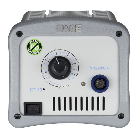
Page 4: Power Supply Features
Power Supply Features FRONT BACK ST 30 ST 50 ST 65 ©2012 PACE Inc., Southern Pines North Carolina All Rights Reserved Page 4 of 20... - Page 5 ST 70 ST 75 ST 115 ©2012 PACE Inc., Southern Pines North Carolina All Rights Reserved Page 5 of 20...
- Page 6 Shop air connection Connection for regulated air supply (ST 65 power supply only) Foot pedal connection Optional control for pressure / vacuum handpiece activation. (Required for TJ-85) ©2012 PACE Inc., Southern Pines North Carolina All Rights Reserved Page 6 of 20...
-
Page 7: Safety Guidelines
Always store the handpiece in its holder. Be sure to place the handpiece in its holder after use and allow heater / tip to cool before storing. 4. Always use PACE systems in a well ventilated area. A fume extraction system such as those available from PACE are highly, recommended to help protect personnel from solder flux fumes. -
Page 8: Handpiece Connection (All Models)
Air Supply Connection (For ST 65 Only) The ST 65 system utilizes an integral air venturi system to provide air pressure and vacuum for any connected PACE handpiece requiring air/vacuum. Your in-house air supply must be connected to the system power source. -
Page 9: Handpiece Vacuum/Pressure (St 65, St 75, & St 115)
1. Insert the female end of the power cord into the AC Power Receptacle on the rear panel of the power source. 2. Plug the prong end (male end) of the power cord into an appropriate 3 wire grounded AC supply receptacle. ©2012 PACE Inc., Southern Pines North Carolina All Rights Reserved Page 9 of 20... -
Page 10: Operation
30 minute Setback and 30 minute Auto Off, which can be turned off by the switch on the back of the unit. When Setback mode has been entered, the temperature will be set to 176C (350 ©2012 PACE Inc., Southern Pines North Carolina All Rights Reserved... -
Page 11: Digital Temperature Controlled Power Supplies (St 50, & St 115)
5. The displayed temperature will decrease and stabilize at 177°C (350°F) when the system is in Temperature Setback. 6. "OFF" with stable display when the Set Tip Temperature has been set to Off (below minimum set tip temperature). ©2012 PACE Inc., Southern Pines North Carolina All Rights Reserved Page 11 of 20... -
Page 12: Temperature Setback Mode
Exiting Auto Off: Auto Off can be exited; returning to normal operation by: 1. Pressing and releasing a Key (either of the 3 keys), or 2. By turning the Power Switch OFF (“0”) and then back ON (“1”). ©2012 PACE Inc., Southern Pines North Carolina All Rights Reserved Page 12 of 20... -
Page 13: Customizing Your System
6. The LED Display now shows the stored default Low ("Lo") Temperature Limit with the display alternating to show "Lo" and the stored limit. Choose one of the following: ©2012 PACE Inc., Southern Pines North Carolina All Rights Reserved Page 13 of 20... -
Page 14: Temperature Setback
454 °C (850 °F) “LO” (Lower) Temperature Limit 204 °C (400 °F) Set Temperature “OFF” Tip Offset Constant “0” Temperature Setback Enabled, 30 minutes Auto Off Enabled, 30 minutes ©2012 PACE Inc., Southern Pines North Carolina All Rights Reserved Page 14 of 20... -
Page 15: Power Module Controlled Power Supply (St 70)
LED never illuminates, check for a faulty handpiece or tip heater cartridge. LED in Set back- The LED will be Amber or Green depending on the color when it entered Setback, or Auto Off. Replacement Power Modules ©2012 PACE Inc., Southern Pines North Carolina All Rights Reserved Page 15 of 20... - Page 16 399 ºC (750 °F) 1207-0446-07-P1 Black 427 ºC (800 °F) 1207-0446-08-P1 Silver 454 ºC (850 °F) *Note: Each ST-70 system includes (1) each 6.5, 7.0, & 7.5 power modules ©2012 PACE Inc., Southern Pines North Carolina All Rights Reserved Page 16 of 20...
-
Page 17: System Calibration
2. Tip heater Cartridge Adjustment. This feature will only work with TD-100, MT-100, and TP-100 handpieces. The PACE ST 30, ST 65, and ST 75 feature a temperature adjustment. This adjustment is located within the small hole on the front panel and may be accessed using a small flat blade screwdriver. -
Page 18: Corrective Maintenance
Refer to the appropriate handpiece manual. “Over Circuit Error” The handpiece heater assembly may be defective. Refer to the appropriate handpiece manual Contact PACE or your authorized local representative for assistance. Power Source Most malfunctions are simple and easy to correct. -
Page 19: Service
Replaceable VisiFilter Elements - Package of 10 1309-0027-P10 Replaceable VisiFilter Elements - Package of 50 1309-0027-P50 Service Please contact PACE or your local distributor for service and repair. ©2012 PACE Inc., Southern Pines North Carolina All Rights Reserved Page 19 of 20... -
Page 20: Pace Limited Warranty Statement
Warranty service may be obtained by contacting the appropriate PACE Company or local Authorized PACE distributor as set forth below to determine if return of any item is required, or if repairs can be made by the user in the field. Any warranty or other claim with respect to the products must be made with sufficient evidence of purchase and date of receipt, otherwise user’s rights under this warranty shall be...
Need help?
Do you have a question about the IntelliHeat ST 30 and is the answer not in the manual?
Questions and answers