Sign In
Upload
Download
Table of Contents
Contents
Add to my manuals
Delete from my manuals
Share
URL of this page:
HTML Link:
Bookmark this page
Add
Manual will be automatically added to "My Manuals"
Print this page
×
Bookmark added
×
Added to my manuals
Manuals
Brands
Pace Manuals
Soldering Gun
ST 45
Operation and maintenance manual
Pace ST 45 Operation And Maintenance Manual
Soldering systems
Hide thumbs
1
Table Of Contents
2
3
4
5
6
7
8
9
10
11
12
13
14
15
16
17
18
19
20
page
of
20
Go
/
20
Contents
Table of Contents
Bookmarks
Table of Contents
Table of Contents
Introduction
Specifications
Parts Identification
Safety Guidelines, English Language
Safety Guidelines, French Language
Safety Guidelines, German Language
Safety Guidelines, Italian Language
Safety Guidelines, Portuguese Language
Safety Guidelines, Spanish Language
Safety Guidelines, Swedish Language
System Set-Up
Mounting Options
Tip & Tool Stand
Handpiece Connection
System Power up
Heater Burn in
Tip Installation
Definitions
Quick Start Procedure
Operation
LED Display, Normal Operation
LED Display, Temperature Adjust Mode
Temperature Setback
Auto off Safety System
Customizing Your System
Introduction
Entering Set-Up Mode
Password
Temperature Scale
Temperature Limits
Offset Constant
Temperature Setback
Auto off
Temperature Display Impedance
Exiting Set-Up Mode
Factory Settings
Corrective Maintenance
System Accuracy and Calibration
LED Display Message Codes
Power Source
Handpieces
Heater Replacement
Packing List/Spare Parts
Service
Limited Warranty
Contact Information
Advertisement
Quick Links
1
System Set-Up
Download this manual
WORLDWIDE
Operation and Maintenance Manual for the
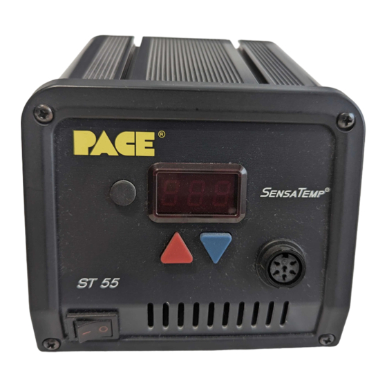
ST 45 & ST 55 Soldering Systems
P/N 5050-0453
Rev D
Table of
Contents
Previous
Page
Next
Page
1
2
3
4
5
Advertisement
Table of Contents
Need help?
Do you have a question about the ST 45 and is the answer not in the manual?
Ask a question
Questions and answers
Related Manuals for Pace ST 45
Soldering Gun Pace ST 40A Operation & Maintenance Manual
(44 pages)
Soldering Gun Pace ST 25 Operation And Maintenance Manual
St 25 soldering system sodrtek (11 pages)
Soldering Gun Pace ST 25 Operation And Maintenance Manual
(14 pages)
Soldering Gun Pace SODRTEK ST 25 Operation And Maintenance Manual
Soldering system (11 pages)
Soldering Gun Pace SensaTemp ST35 Quick Start Manual
(6 pages)
Soldering Gun Pace ST35 w/PS-90 Iron Operation And Maintenance Manual
(11 pages)
Soldering Gun Pace SODRTEK ST 325 Operation And Maintenance Manual
Digital convective soldering/desoldering system (31 pages)
Soldering Gun Pace ST 65 Operation & Maintenance Manual
(24 pages)
Soldering Gun Pace IntelliHeat ST 30 Operation And Maintenance Manual
Power sources (20 pages)
Soldering Gun Pace Sodrtek ST 125 Operation And Maintenance Manual
Analog desoldering system (13 pages)
Soldering Gun Pace ST125 Operation And Maintenance Manual
Soldering/desoldering system (12 pages)
Soldering Gun Pace 20A Operation & Maintenance Manual
(27 pages)
Soldering Gun Pace ST 115 Operation & Maintenance Manual
(46 pages)
Soldering Gun Pace ST 55 Operation And Maintenance Manual
Soldering systems (20 pages)
Soldering Gun Pace ST 85 Operation & Maintenance Manual
(41 pages)
Soldering Gun Pace SODRTEK ST 300 Operation And Maintenance Manual
Analog convective soldering/desoldering system (14 pages)
This manual is also suitable for:
St 55
St 45e
St 55e
Table of Contents
Save PDF
Print
Rename the bookmark
Delete bookmark?
Delete from my manuals?
Login
Sign In
OR
Sign in with Facebook
Sign in with Google
Upload manual
Upload from disk
Upload from URL


Need help?
Do you have a question about the ST 45 and is the answer not in the manual?
Questions and answers