Table of Contents
Advertisement
Quick Links
Advertisement
Table of Contents

Related Manuals for IEI Technology IMBA-H810


Summary of Contents for IEI Technology IMBA-H810
-
Page 1: User Manual
IMBA-H810 ATX Motherboard MODEL: IMBA-H810 ATX Motherboard Supports 4th Generation LGA1150 Intel® Core™ i7/i5/i3, Pentium® or Celeron® CPU, Intel® H81 Chipset, DDR3, VGA, DVI-D, iDP, SATA 6Gb/s, USB 3.0, Dual Intel® PCIe GbE, HD Audio and RoHS User Manual Page i... - Page 2 IMBA-H810 ATX Motherboard Revision Date Version Changes April 1, 2015 1.00 Initial release Page ii...
- Page 3 IMBA-H810 ATX Motherboard Copyright COPYRIGHT NOTICE The information in this document is subject to change without prior notice in order to improve reliability, design and function and does not represent a commitment on the part of the manufacturer. In no event will the manufacturer be liable for direct, indirect, special, incidental, or consequential damages arising out of the use or inability to use the product or documentation, even if advised of the possibility of such damages.
-
Page 4: Table Of Contents
PTIONAL TEMS 3 CONNECTORS ......................15 3.1 P ..............16 ERIPHERAL NTERFACE ONNECTORS 3.1.1 IMBA-H810 Layout..................16 3.1.2 Peripheral Interface Connectors ..............17 3.1.3 External Interface Panel Connectors............... 18 3.2 I ..............19 NTERNAL ERIPHERAL ONNECTORS 3.2.1 +12V Power Connector ................... 19 3.2.2 Additional Power Connector ................ - Page 5 IMBA-H810 ATX Motherboard 3.2.12 Front Panel Connector .................. 28 3.2.13 I C Connector ....................29 3.2.14 Internal DisplayPort Connector ..............30 3.2.15 Keyboard and Mouse Connector ..............31 3.2.16 LAN1 LED Connector..................32 3.2.17 LAN2 LED Connector..................33 3.2.18 Parallel Port Connector ................34 3.2.19 PCI Slots ......................
- Page 6 IMBA-H810 ATX Motherboard 4.2.2 Socket LGA1150 Cooling Kit Installation............62 4.2.3 DIMM Installation ................... 64 4.3 PCI ................64 NSTALLATION 4.4 S ..................66 YSTEM ONFIGURATION 4.4.1 AT/ATX Power Mode Setting ................66 4.4.2 Clear CMOS Button..................67 4.4.3 Flash Descriptor Security Override..............67 4.4.4 mSATA Setup Jumper ..................
- Page 7 IMBA-H810 ATX Motherboard 5.3.11 Serial Port Console Redirection..............97 5.3.12 iEi Feature ....................100 5.4 C ......................... 101 HIPSET 5.4.1 PCH-IO Configuration .................. 102 5.4.1.1 PCI Express Configuration ..............104 5.4.1.2 PCH Azalia Configuration ..............105 5.4.2 System Agent (SA) Configuration ..............106 5.4.2.1 Graphics Configuration................
- Page 8 IMBA-H810 ATX Motherboard F.1 H IPB P AZARDOUS ATERIALS ISCLOSURE ABLE FOR RODUCTS ERTIFIED AS HS C 2002/95/EC W ........153 OMPLIANT NDER ITHOUT ERCURY Page viii...
- Page 9 IMBA-H810 ATX Motherboard List of Figures Figure 1-1: IMBA-H810 ........................2 Figure 1-2: Connectors ........................4 Figure 1-3: IMBA-H810 Dimensions (mm) ..................5 Figure 1-4: Data Flow Diagram......................6 Figure 3-1: Peripheral Interface Connectors ................16 Figure 3-2: +12V Power Connector Pinout Location ..............19 Figure 3-3: Additional Power Connector Location..............20 Figure 3-4: ATX Power Connector Location ................21...
- Page 10 IMBA-H810 ATX Motherboard Figure 3-27: RS-232 Serial Port Connector Locations..............42 Figure 3-28: RS-422/485 Connector Location................43 Figure 3-29: SMBus Connector Location ...................44 Figure 3-30: SPI Flash Connector Location................45 Figure 3-31: SPI EC Flash Connector Location.................46 Figure 3-32: TPM Connector Location..................47 Figure 3-33: USB 2.0 Connector (Type A) Pinout Location............48 Figure 3-34: USB 2.0 Connector Pinout Locations ..............49...
- Page 11 IMBA-H810 ATX Motherboard Figure 6-6: Chipset Driver Setup Operations ................. 120 Figure 6-7: Chipset Driver Installation Finish Screen............120 Figure 6-8: Graphics Driver Welcome Screen ................ 121 Figure 6-9: Graphics Driver License Agreement..............122 Figure 6-10: Graphics Driver Read Me File ................122 Figure 6-11: Graphics Driver Setup Operations ..............
- Page 12 IMBA-H810 ATX Motherboard List of Tables Table 1-1: IMBA-H810 Specifications ...................9 Table 2-1: Packing List.........................12 Table 2-2: Optional Items......................14 Table 3-1: Peripheral Interface Connectors ................18 Table 3-2: Rear Panel Connectors ....................18 Table 3-3: +12V Power Connector Pinouts ................19 Table 3-4: Additional Power Connector Pinouts ...............20 Table 3-5: ATX Power Connector Pinouts .................21...
- Page 13 IMBA-H810 ATX Motherboard Table 3-28: TPM Connector Pinouts ...................47 Table 3-29: USB 2.0 Connector (Type A) Pinouts ..............48 Table 3-30: USB 2.0 Connector Pinouts ..................49 Table 3-31: USB 2.0 Port Pinouts....................51 Table 3-32: LAN2 Pinouts ......................51 Table 3-33: USB 3.0 Port Pinouts....................52 Table 3-34: LAN1 Pinouts ......................52...
- Page 14 IMBA-H810 ATX Motherboard BIOS Menus BIOS Menu 1: Main ........................76 BIOS Menu 2: Advanced ......................77 BIOS Menu 3: ACPI Configuration ....................78 BIOS Menu 4: RTC Wake Settings ....................79 BIOS Menu 5: Trusted Computing ....................80 BIOS Menu 6: CPU Configuration ....................81 BIOS Menu 7: SATA Configuration .....................83...
-
Page 15: Introduction
IMBA-H810 ATX Motherboard Chapter Introduction Page 1... -
Page 16: Introduction
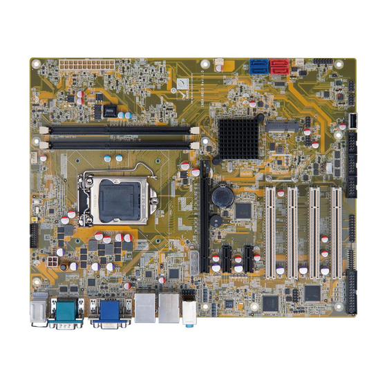
IMBA-H810 ATX Motherboard 1.1 Introduction Figure 1-1: IMBA-H810 The IMBA-H810 is an ATX motherboard. It accepts a Socket LGA1150 Intel® Core™ i7/i5/i3, Pentium® or Celeron® processor and supports two 240-pin 1600/1333 MHz dual-channel DDR3/DDR3L DIMMs up to 16 GB. The IMBA-H810 provides two GbE interfaces through the Intel® I218-V (with Intel® AMT 9.0 support) and the Intel®... -
Page 17: Features
IMBA-H810 ATX Motherboard 1.2 Features Some of the IMBA-H810 motherboard features are listed below: ATX form factor 4th generation LGA1150 Intel® Core™ i7/i5/i3, Pentium® or Celeron® processor supported Intel® H81 chipset Two 240-pin 1600/1333 MHz dual-channel DDR3/DDR3L DIMMs support up to 16 GB Two Intel®... -
Page 18: Connectors
IMBA-H810 ATX Motherboard 1.3 Connectors The connectors on the IMBA-H810 are shown in the figure below. Figure 1-2: Connectors Page 4... -
Page 19: Dimensions
IMBA-H810 ATX Motherboard 1.4 Dimensions The main dimensions of the IMBA-H810 are shown in the diagram below. Figure 1-3: IMBA-H810 Dimensions (mm) Page 5... -
Page 20: Data Flow
IMBA-H810 ATX Motherboard 1.5 Data Flow Figure 1-4 shows the data flow between the system chipset, the CPU and other components installed on the motherboard. Figure 1-4: Data Flow Diagram Page 6... -
Page 21: Technical Specifications
IMBA-H810 ATX Motherboard 1.6 Technical Specifications The IMBA-H810 technical specifications are listed below. Specification/Model IMBA-H810 Form Factor 4th generation LGA1150 Intel® Core™ i7/i5/i3, Pentium® or CPU Supported Celeron® CPU Chipset Intel® H81 Two 240-pin 1600/1333 MHz dual-channel unbuffered Memory DDR3/DDR3L SDRAM DIMMs supported (system max. 16 GB) Intel®... - Page 22 IMBA-H810 ATX Motherboard I/O Interface Connectors Line-in, line-out and mic-in audio jacks on rear panel Audio Connectors One internal front panel audio connector (10-pin header) Chassis Intrusion One 2-pin header Digital I/O 8-bit digital I/O Ethernet Two RJ-45 GbE ports...
-
Page 23: Table 1-1: Imba-H810 Specifications
Intel® Core™ i7-4770K CPU with two 4 GB 1333 MHz DDR3 Power Consumption memory) Operating -20ºC ~ 60ºC Temperature Storage Temperature -30ºC ~ 70ºC Operating Humidity 5% ~ 95% (non-condensing) Physical Specifications Dimensions 244 mm x 305 mm Weight (GW/NW) 1200 g/700 g Table 1-1: IMBA-H810 Specifications Page 9... -
Page 24: Packing List
IMBA-H810 ATX Motherboard Chapter Packing List Page 10... -
Page 25: Anti-Static Precautions
Only handle the edges of the PCB: Don't touch the surface of the motherboard. Hold the motherboard by the edges when handling. 2.2 Unpacking Precautions When the IMBA-H810 is unpacked, please do the following: Follow the anti-static guidelines above. Make sure the packing box is facing upwards when opening. -
Page 26: Packing List
If any of the components listed in the checklist below are missing, do not proceed with the installation. Contact the IEI reseller or vendor the IMBA-H810 was purchased from or contact an IEI sales representative directly by sending an email to ales@ieiworld.com. -
Page 27: Optional Items
IMBA-H810 ATX Motherboard 2.4 Optional Items The following are optional components which may be separately purchased: Item and Part Number Image RS-422/485 cable, 200 mm (P/N: 32205-003800-300-RS) Dual RS-232 cable, 230 mm, P=2.54 (P/N: 19800-000051-RS) PS/2 KB/MS Y-cable with bracket, 220 mm (P/N: 19800-000075-RS) Dual-port USB 3.0 cable with bracket... -
Page 28: Table 2-2: Optional Items
IMBA-H810 ATX Motherboard Item and Part Number Image DisplayPort to HDMI converter board (for IEI iDP connector) (P/N: DP-HDMI-R10) DisplayPort to LVDS converter board (for IEI iDP connector) (P/N: DP-LVDS-R10) DisplayPort to VGA converter board (for IEI iDP connector) (P/N: DP-VGA-R10) -
Page 29: Connectors
IMBA-H810 ATX Motherboard Chapter Connectors Page 15... -
Page 30: Peripheral Interface Connectors
IMBA-H810 ATX Motherboard 3.1 Peripheral Interface Connectors This chapter details all the peripheral interface connectors. 3.1.1 IMBA-H810 Layout The figure below shows all the peripheral interface connectors. Figure 3-1: Peripheral Interface Connectors Page 16... -
Page 31: Peripheral Interface Connectors
IMBA-H810 ATX Motherboard 3.1.2 Peripheral Interface Connectors The table below lists all the connectors on the board. Connector Type Label 4-pin Molex power +12V power connector CPU12V1 connector Additional power connector 4-pin connector ATXPWR1 ATX power connector 24-pin connector ATX1... -
Page 32: External Interface Panel Connectors
IMBA-H810 ATX Motherboard Connector Type Label PCIe x16 slot PCIe x16 slot PCIEX16_1 Power button Push button PWR_SW1 SATA 3Gb/s drive connector 7-pin SATA connector SATA3, SATA4 SATA 6Gb/s drive connector 7-pin SATA connector S_ATA1, S_ATA2 COM3, COM5, Serial port, RS-232... -
Page 33: Internal Peripheral Connectors
IMBA-H810 ATX Motherboard 3.2 Internal Peripheral Connectors The section describes all of the connectors on the IMBA-H810. 3.2.1 +12V Power Connector CN Label: CPU12V1 4-pin Molex power connector, p=4.2 mm CN Type: CN Location: See Figure 3-2 CN Pinouts: See Table 3-3 This connector provides power to the CPU. -
Page 34: Atx Power Connector
IMBA-H810 ATX Motherboard The additional power connector provides extra +12V and +5V power to the system. Figure 3-3: Additional Power Connector Location Description +12V Table 3-4: Additional Power Connector Pinouts 3.2.3 ATX Power Connector CN Label: ATX1 24-pin connector, p=4.2 mm... -
Page 35: Figure 3-4: Atx Power Connector Location
IMBA-H810 ATX Motherboard Figure 3-4: ATX Power Connector Location Description Description +3.3V +3.3V +3.3V -12V PS_ON Power good 5VSB +12V +12V +3.3V Table 3-5: ATX Power Connector Pinouts Page 21... -
Page 36: Battery Connector
IMBA-H810 ATX Motherboard 3.2.4 Battery Connector CAUTION: Risk of explosion if battery is replaced by an incorrect type. Only certified engineers should replace the on-board battery. Dispose of used batteries according to instructions and local regulations. CN Label: BAT1 CN Type:... -
Page 37: Chassis Intrusion Connector
IMBA-H810 ATX Motherboard 3.2.5 Chassis Intrusion Connector CN Label: CHASSIS1 2-pin header, p=2.54 mm CN Type: CN Location: F igure 3-6 CN Pinouts: See Table 3-6 The chassis intrusion connector is for a chassis intrusion detection sensor or switch that detects if a chassis component is removed or replaced. -
Page 38: Digital I/O Connector
IMBA-H810 ATX Motherboard Figure 3-7: DDR3 DIMM Slot Locations 3.2.7 Digital I/O Connector CN Label: DIO1 CN Type: 10-pin header, p=2.54 mm CN Location: See Figure 3-8 CN Pinouts: See Table 3-7 The digital I/O connector provides programmable input and output for external devices. -
Page 39: Ec Debug Connector
IMBA-H810 ATX Motherboard Description Description Output 1 Output 0 Input 3 Input 2 Input 1 Input 0 Table 3-7: Digital I/O Connector Pinouts 3.2.8 EC Debug Connector CN Label: 18-pin header, p=2 mm CN Type: CN Location: See Figure 3-9... -
Page 40: Fan Connector (Cpu)
IMBA-H810 ATX Motherboard Description Description EC_EPP_PD6 EC_EPP_KSI5 EC_EPP_PD7 EC_EPP_KSI4 Table 3-8: EC Debug Connector Pinouts 3.2.9 Fan Connector (CPU) CN Label: CPU_FAN1 CN Type: 4-pin wafer, p=2.54 mm CN Location: See Figure 3-10 CN Pinouts: See Table 3-9 The fan connector attaches to a CPU cooling fan. -
Page 41: Front Panel Audio Connector
IMBA-H810 ATX Motherboard CN Location: See Figure 3-11 CN Pinouts: See Table 3-10 Each fan connector attaches to a system cooling fan. Figure 3-11: System Fan Connector Locations Description FANIO +12V (PWM) Table 3-10: System Fan Connector Pinouts 3.2.11 Front Panel Audio Connector... -
Page 42: Front Panel Connector
IMBA-H810 ATX Motherboard Figure 3-12: Front Panel Audio Connector Location Description Description MIC2-L MIC2-R Presence# LINE2-R MIC2-JD FRONT-IO LINE2-L LINE2-JD Table 3-11: Front Panel Audio Connector Pinouts 3.2.12 Front Panel Connector CN Label: F_PANEL1 14-pin header, p=2.54 mm CN Type:... -
Page 43: I 2 C Connector
IMBA-H810 ATX Motherboard Figure 3-13: Front Panel Connector Location Function Description Function Description BEEP_PWR Power LED Speaker PWRBTN_SW# PC_BEEP Power Button EXTRST- HDD LED Reset SATA_LED# Table 3-12: Front Panel Connector Pinouts 3.2.13 I C Connector CN Label: CN Type: 4-pin wafer, p=1.25 mm... -
Page 44: Internal Displayport Connector
IMBA-H810 ATX Motherboard Figure 3-14: I C Connector Location Description PCH_GP38 PCH_GP39 Table 3-13: I C Connector Pinouts 3.2.14 Internal DisplayPort Connector CN Label: CN Type: 20-pin box header, p=2 mm CN Location: See Figure 3-15 See Table 3-14 CN Pinouts: The DisplayPort connector supports HDMI, LVDS, VGA, DVI and DisplayPort graphics interfaces with up to 3840x2160 resolutions. -
Page 45: Keyboard And Mouse Connector
IMBA-H810 ATX Motherboard Figure 3-15: Internal DisplayPort Connector Location Description Description AUXP LANE1N AUXN LANE1P LANE2P LANE3N LANE2N LANE3P LANE0P AUX_CTRL_DET_D LANE0N +3.3V Table 3-14: Internal DisplayPort Connector Pinouts 3.2.15 Keyboard and Mouse Connector CN Label: KB_MS1 CN Type: 6-pin wafer, p=2 mm... -
Page 46: Lan1 Led Connector
IMBA-H810 ATX Motherboard Figure 3-16: Keyboard and Mouse Connector Location Description Mouse Data Mouse Clock Keyboard Data Keyboard Clock Table 3-15: Keyboard and Mouse Connector Pinouts 3.2.16 LAN1 LED Connector CN Label: LED_LAN3 CN Type: 2-pin header, p=2.54 mm F igure 3-17... -
Page 47: Lan2 Led Connector
IMBA-H810 ATX Motherboard Figure 3-17: LAN1 LED Connector Location Description +3.3V LAN1_LED_LINK#_ACT Table 3-16: LAN1 LED Connector (LED_LAN3) Pinouts 3.2.17 LAN2 LED Connector CN Label: LED_LAN4 CN Type: 2-pin header, p=2.54 mm CN Location: See Figure 3-18 See Table 3-17... -
Page 48: Parallel Port Connector
IMBA-H810 ATX Motherboard Figure 3-18: LAN2 LED Connector Location Description +3.3V LAN2_LED_LINK#_ACT Table 3-17: LAN2 LED Connector (LED_LAN4) Pinouts 3.2.18 Parallel Port Connector CN Label: LPT1 CN Type: 26-pin box header, p=2.54 mm CN Location: See Figure 3-19 CN Pinouts:... -
Page 49: Pci Slots
IMBA-H810 ATX Motherboard Figure 3-19: Parallel Port Connector Location Description Description STROBE# DATA0 DATA1 DATA2 DATA3 DATA4 DATA5 DATA6 DATA7 ACKNOWLEDGE# BUSY PAPER EMPTY PRINTER SELECT AUTO FORM FEED # ERROR# INITIALIZE# PRINTER SELECT LN# Table 3-18: Parallel Port Connector Pinouts 3.2.19 PCI Slots... -
Page 50: Pcie Mini Slot
IMBA-H810 ATX Motherboard Figure 3-20: PCI Slot Locations 3.2.20 PCIe Mini Slot CN Label: PCIe Mini slot CN Type: CN Location: F igure 3-21 CN Pinouts: See Table 3-19 The PCIe Mini slot is for installing a full-size PCIe Mini expansion card, including an mSATA card. -
Page 51: Figure 3-21: Pcie Mini Slot Location
IMBA-H810 ATX Motherboard Figure 3-21: PCIe Mini Slot Location Description Description PCIE_WAKE# +3.3V 1.5V MSATA_CLK# MSATA _CLK PLTRST_N +3.3V PLTRST_N SATA_RX+ +3.3V SATA_RX- 1.5V SMB_CLK SATA_TX- SMB_DATA SATA_TX+ USB_DATA- USB_DATA+ +3.3V +3.3V +3.3V Page 37... -
Page 52: Pcie X1 Slot
IMBA-H810 ATX Motherboard Description Description CLINK_CLK CLINK_DATA 1.5V CLINK_RST# MSATA_DET +3.3V Table 3-19: PCIe Mini Slot Pinouts 3.2.21 PCIe x1 Slot CN Label: PCIEX1_1, PCIEX1_2 PCIe x1 slot CN Type: CN Location: See Figure 3-22 The PCIe x1 slots are for PCIe x1 expansion cards. -
Page 53: Power Button
IMBA-H810 ATX Motherboard Figure 3-23: PCIe x16 Slot Location 3.2.23 Power Button CN Label: PWR_SW1 CN Type: Push button See Figure 3-24 CN Location: The on-board power button controls system power. Figure 3-24: Power Button Location Page 39... -
Page 54: Sata 3Gb/S Drive Connector
IMBA-H810 ATX Motherboard 3.2.24 SATA 3Gb/s Drive Connector CN Label: SATA3, SATA4 7-pin SATA drive connector CN Type: CN Location: See Figure 3-25 CN Pinouts: See Table 3-20 The SATA drive connectors can be connected to SATA drives and supports up to 3Gb/s data transfer rate. -
Page 55: Sata 6Gb/S Drive Connector
IMBA-H810 ATX Motherboard NOTE: If the user shorts the mSATA setup jumper (MSATA_SW1) to force the system to enable mSATA device or an mSATA device is detected, the SATA4 connector will be disabled. Please refer to Section 0. 3.2.25 SATA 6Gb/s Drive Connector... -
Page 56: Serial Port Connector, Rs-232
IMBA-H810 ATX Motherboard Description SATA_TX+ SATA_TX- SATA_RX- SATA RX+ Table 3-21: SATA 6Gb/s Drive Connector Pinouts 3.2.26 Serial Port Connector, RS-232 CN Label: COM3, COM5, COM6 CN Type: 10-pin box header, p=2.54 mm CN Location: See Figure 3-27 CN Pinouts: See Table 3-22 Each of these connectors provides RS-232 connections. -
Page 57: Serial Port Connector, Rs-422/485
IMBA-H810 ATX Motherboard Description Description Table 3-22: RS-232 Serial Port Connector Pinouts 3.2.27 Serial Port Connector, RS-422/485 CN Label: COM4 CN Type: 4-pin wafer, p=2 mm CN Location: See Figure 3-28 CN Pinouts: See Table 3-23 This connector provides RS-422 or RS-485 communications. -
Page 58: Smbus Connector
IMBA-H810 ATX Motherboard RS-422 Pinouts RS-485 Pinouts Table 3-24: DB-9 RS-422/485 Pinouts 3.2.28 SMBus Connector CN Label: CN Type: 4-pin wafer, p=1.25 mm See Figure 3-29 CN Location: CN Pinouts: See Table 3-25 The SMBus (System Management Bus) connector provides low-speed system management communications. -
Page 59: Spi Flash Connector
IMBA-H810 ATX Motherboard 3.2.29 SPI Flash Connector CN Label: JSPI1 8-pin header, p=2.54 mm CN Type: CN Location: See Figure 3-30 CN Pinouts: See Table 3-26 The SPI flash connector is used to flash the SPI ROM. Figure 3-30: SPI Flash Connector Location... -
Page 60: Spi Flash Connector, Ec
IMBA-H810 ATX Motherboard 3.2.30 SPI Flash Connector, EC CN Label: JSPI2 8-pin header, p=2.54 mm CN Type: CN Location: See Figure 3-31 CN Pinouts: See Table 3-27 The SPI flash connector is used to flash the EC ROM. Figure 3-31: SPI EC Flash Connector Location... -
Page 61: Usb 2.0 Connector (Type A)
IMBA-H810 ATX Motherboard The TPM connector connects to a TPM module. Figure 3-32: TPM Connector Location Description Description LCLK LFRAME# LRERST# LAD3 LAD2 +3.3V LAD1 LAD0 SB3V SERIRQ GLKRUN# LPCPD# LDRQ# Table 3-28: TPM Connector Pinouts 3.2.32 USB 2.0 Connector (Type A) -
Page 62: Usb 2.0 Connectors
IMBA-H810 ATX Motherboard Figure 3-33: USB 2.0 Connector (Type A) Pinout Location Description DATA- DATA+ GROUND Table 3-29: USB 2.0 Connector (Type A) Pinouts 3.2.33 USB 2.0 Connectors CN Label: USB1, USB2 8-pin header, p=2.54 mm CN Type: CN Location:... -
Page 63: External Peripheral Interface Connector Panel
IMBA-H810 ATX Motherboard Figure 3-34: USB 2.0 Connector Pinout Locations Description Description USB_DATA- USB_DATA+ USB_DATA+ USB_DATA- Table 3-30: USB 2.0 Connector Pinouts 3.3 External Peripheral Interface Connector Panel The figure below shows the external peripheral interface connector (EPIC) panel. The... -
Page 64: Audio Connector
3.3.2 Ethernet and USB 2.0 Connectors CN Label: LAN2_USB2 CN Type: RJ-45, USB 2.0 CN Location: See Figure 3-35 CN Pinouts: See Table 3-31 and Table 3-32 There are two external USB 2.0 connectors on the IMBA-H810. Description Description USB_DATA- USB_DATA- Page 50... -
Page 65: Ethernet And Usb 3.0 Connectors
CN Label: LAN1_USB1 RJ-45, USB 3.0 CN Type: CN Location: See Figure 3-35 CN Pinouts: See Table 3-33 and Table 3-34 There are two external USB 3.0 connectors on the IMBA-H810. Description Description USB_DATA- USB_DATA- USB_DATA+ USB_ DATA+ Page 51... -
Page 66: Ps/2 Keyboard And Mouse Connectors
IMBA-H810 ATX Motherboard Description Description USB3_RX- USB3_RX- USB3_RX+ USB3_ RX+ USB3_TX- USB3_TX- USB3_TX+ USB3_TX+ Table 3-33: USB 3.0 Port Pinouts Each LAN connector connects to a local network Description Description LAN1_MDI0P LAN1_MDI2P LAN1_MDI0N LAN1_MDI2N LAN1_MDI1P LAN1_MDI3P LAN1_MDI1N LAN1_MDI3N Table 3-34: LAN1 Pinouts 3.3.4 PS/2 Keyboard and Mouse Connectors... -
Page 67: Serial Port Connector (Com1)
IMBA-H810 ATX Motherboard Figure 3-38: PS/2 Keyboard and Mouse Connectors 3.3.5 Serial Port Connector (COM1) CN Label: COM1 (top) CN Type: DB-9 connector CN Location: See Figure 3-35 CN Pinouts: See Table 3-36 and Figure 3-39 The serial port connects to a RS-232 serial communications device. -
Page 68: Serial Port Connector (Com2)
IMBA-H810 ATX Motherboard 3.3.6 Serial Port Connector (COM2) CN Label: COM1 (bottom) DB-9 connector CN Type: CN Location: See Figure 3-35 CN Pinouts: See Table 3-37 and Figure 3-40 The serial port connects to a RS-232 serial communications device. Description... -
Page 69: Figure 3-41: Vga Connector
IMBA-H810 ATX Motherboard Description Description DVI_DATA2# DVI_DATA2 DDC CLK DDC DATA DVI_DATA1# DVI_DATA1 Hot Plug Detect HPDET DVI_DATA0# DVI_DATA0 DVI_CLK DVI_CLK# Table 3-38: DVI-D Connector Pinouts The 15-pin VGA connector connects to a monitor that accepts a standard VGA input. -
Page 70: Installation
IMBA-H810 ATX Motherboard Chapter Installation Page 56... -
Page 71: Anti-Static Precautions
Electrostatic discharge (ESD) can cause serious damage to electronic components, including the IMBA-H810. Dry climates are especially susceptible to ESD. It is therefore critical that whenever the IMBA-H810 or any other electrical component is handled, the following anti-static precautions are strictly adhered to. - Page 72 This helps to prevent potential ESD damage. Turn all power to the IMBA-H810 off: When working with the IMBA-H810, make sure that it is disconnected from all power supplies and that no electricity is being fed into the system.
-
Page 73: Socket Lga1150 Cpu Installation
IMBA-H810 ATX Motherboard 4.2.1 Socket LGA1150 CPU Installation WARNING: CPUs are expensive and sensitive components. When installing the CPU please be careful not to damage it in anyway. Make sure the CPU is installed properly and ensure the correct cooling kit is properly installed. -
Page 74: Figure 4-2: Remove Protective Cover
IMBA-H810 ATX Motherboard Figure 4-2: Remove Protective Cover Step 3: Inspect the CPU socket. Make sure there are no bent pins and make sure the socket contacts are free of foreign material. If any debris is found, remove it with compressed air. -
Page 75: Figure 4-3: Insert The Socket Lga1150 Cpu
IMBA-H810 ATX Motherboard Step 7: Insert the CPU. Gently insert the CPU into the socket. If the CPU pins are properly aligned, the CPU should slide into the CPU socket smoothly. See Figure 4-3. Figure 4-3: Insert the Socket LGA1150 CPU Step 8: Close the CPU socket. -
Page 76: Socket Lga1150 Cooling Kit Installation
IMBA-H810 ATX Motherboard Step 9: Connect the 12 V power to the board. Connect the 12 V power from the power supply to the board. Step 0: 4.2.2 Socket LGA1150 Cooling Kit Installation WARNING: DO NOT attempt to install a push-pin cooling fan. -
Page 77: Figure 4-5: Cooling Kit Support Bracket
Secure the cooling kit by fastening the four retention screws of the cooling kit. Step 5: Connect the fan cable. Connect the cooling kit fan cable to the CPU fan connector on the IMBA-H810. Carefully route the cable and avoid heat generating chips and fan blades.Step 0:... -
Page 78: Dimm Installation
IMBA-H810 ATX Motherboard 4.2.3 DIMM Installation To install a DIMM, please follow the steps below and refer to Figure 4-6. Figure 4-6: DIMM Installation Step 1: Open the DIMM socket handles. Open the two handles outwards as far as they can. See Figure 4-6. -
Page 79: Figure 4-7: Remove The Retention Screws For The Pcie Mini Card
IMBA-H810 ATX Motherboard Step 2: Remove the retention screws. Remove the two retention screws secured on the motherboard as shown in F igure 4-7. Figure 4-7: Remove the Retention Screws for the PCIe Mini Card Step 3: Insert into the socket at an angle. Line up the notch on the card with the notch on the connector. -
Page 80: System Configuration
IMBA-H810 ATX Motherboard Step 4: Secure the PCIe Mini card. Secure the PCIe Mini card with the retention screws previously removed ( F igure 4-9). Step 0: Figure 4-9: Secure the PCIe Mini Card 4.4 System Configuration The system configuration should be performed before installation. -
Page 81: Clear Cmos Button
IMBA-H810 ATX Motherboard Setting Description ATX power mode (default) AT power mode Table 4-1: AT/ATX Power Mode Switch Settings 4.4.2 Clear CMOS Button To reset the BIOS, remove the on-board battery and press the clear CMOS button for three seconds or more. The clear CMOS button location is shown in Figure 4-11. -
Page 82: Msata Setup Jumper
IMBA-H810 ATX Motherboard Figure 4-12: Flash Descriptor Security Override Jumper Location To update the ME firmware, please follow the steps below. Step 1: Before turning on the system power, short pin 2-3 of the Flash Descriptor Security Override jumper. Step 2: Update the BIOS and ME firmware, and then turn off the system power. -
Page 83: Usb Power Selection
IMBA-H810 ATX Motherboard Figure 4-13: mSATA Setup Jumper Location 4.4.5 USB Power Selection The USB power selection is made through the BIOS menu in “Chipset PCH-IO Configuration”. Use the USB Power SW1 and the USB Power SW2 BIOS options to configure the correspondent USB ports (see Table 4-4) and refer to Table 4-5 to select the USB power source. -
Page 84: Internal Peripheral Device Connections
This section outlines the installation of peripheral devices to the onboard connectors. 4.5.1 SATA Drive Connection The IMBA-H810 is shipped with two SATA drive cables. To connect the SATA drives to the connectors, please follow the steps below. Step 1: Locate the connectors. -
Page 85: Intel ® Amt Setup Procedure
® 4.6 Intel AMT Setup Procedure The IMBA-H810 is featured with the Intel® Active Management Technology (AMT). To enable the Intel® AMT function, follow the steps below. Step 1: Make sure at least one of the memory sockets is installed with a DDR3/DDR3L DIMM. - Page 86 IMBA-H810 ATX Motherboard process. Enter the Intel® current ME password as it requires (the Intel® default password is admin). Step 0: NOTE: To change the password, enter a new password following the strong password rule (containing at least one upper case letter, one lower case letter, one digit and one special character, and be at least eight characters).
-
Page 87: Bios
IMBA-H810 ATX Motherboard Chapter BIOS Page 73... -
Page 88: Introduction
IMBA-H810 ATX Motherboard 5.1 Introduction The BIOS is programmed onto the BIOS chip. The BIOS setup program allows changes to certain system settings. This chapter outlines the options that can be changed. NOTE: Some of the BIOS options may vary throughout the life cycle of the product and are subject to change without prior notice. -
Page 89: Getting Help
IMBA-H810 ATX Motherboard Function Page Up Move to the previous page Page Dn Move to the next page Main Menu – Quit and not save changes into CMOS Status Page Setup Menu and Option Page Setup Menu -- Exit current page and return to Main Menu... -
Page 90: Main
IMBA-H810 ATX Motherboard 5.2 Main The Main BIOS menu (BIOS Menu 1) appears when the BIOS Setup program is entered. The Main menu gives an overview of the basic system information. Aptio Setup Utility – Copyright (C) 2012 American Megatrends, Inc. -
Page 91: Advanced
IMBA-H810 ATX Motherboard The Main menu has two user configurable fields: System Date [xx/xx/xx] Use the System Date option to set the system date. Manually enter the day, month and year. System Time [xx:xx:xx] Use the System Time option to set the system time. Manually enter the hours, minutes and seconds. -
Page 92: Acpi Settings
IMBA-H810 ATX Motherboard 5.3.1 ACPI Settings The ACPI Settings menu (BIOS Menu 3) configures the Advanced Configuration and Power Interface (ACPI) options. Aptio Setup Utility – Copyright (C) 2012 American Megatrends, Inc. Advanced ACPI Settings Select ACPI sleep state the system will enter ACPI Sleep State [S1 only(CPU Stop Cl...]... -
Page 93: Rtc Wake Settings
IMBA-H810 ATX Motherboard 5.3.2 RTC Wake Settings The RTC Wake Settings menu (BIOS Menu 4) enables the system to wake at the specified time. Aptio Setup Utility – Copyright (C) 2012 American Megatrends, Inc. Advanced Wake system with Fixed Time... -
Page 94: Trusted Computing
IMBA-H810 ATX Motherboard Wake up minute Wake up second After setting the alarm, the computer turns itself on from a suspend state when the alarm goes off. 5.3.3 Trusted Computing Use the Trusted Computing menu (BIOS Menu 5) to configure settings related to the Trusted Computing Group (TCG) Trusted Platform Module (TPM). -
Page 95: Cpu Configuration
IMBA-H810 ATX Motherboard 5.3.4 CPU Configuration Use the CPU Configuration menu (BIOS Menu 6) to view detailed CPU specifications or enable the Intel Virtualization Technology. Aptio Setup Utility – Copyright (C) 2012 American Megatrends, Inc. Advanced CPU Configuration Enable for Windows XP and Linux (OS optimized for Intel(R) Core(TM) i3-4330 CPU @ 3.50GHz... - Page 96 IMBA-H810 ATX Motherboard Active Processor Cores [All] Use the Active Processor Cores BIOS option to enable numbers of cores in the processor package. Enable all cores in the processor package. EFAULT Enable one core in the processor package. Intel Virtualization Technology [Disabled] Use the Intel Virtualization Technology option to enable or disable virtualization on the system.
-
Page 97: Sata Configuration
IMBA-H810 ATX Motherboard 5.3.5 SATA Configuration Use the SATA Configuration menu (BIOS Menu 7) to change and/or set the configuration of the SATA devices installed in the system. Aptio Setup Utility – Copyright (C) 2012 American Megatrends, Inc. Advanced SATA Controller(s) -
Page 98: Intel(R) Rapid Start Technology
IMBA-H810 ATX Motherboard 5.3.6 Intel(R) Rapid Start Technology Use the Intel(R) Rapid Start Technology (BIOS Menu 8) menu to configure Intel® Rapid Start Technology support. Aptio Setup Utility – Copyright (C) 2012 American Megatrends, Inc. Advanced Intel(R) Rapid Start Technology... -
Page 99: Amt Configuration
IMBA-H810 ATX Motherboard 5.3.7 AMT Configuration The AMT Configuration menu (BIOS Menu 9) allows the Intel® AMT options to be configured. Aptio Setup Utility – Copyright (C) 2012 American Megatrends, Inc. Advanced Intel AMT [Enabled] Enable/Disable Intel (R) Un-Configure ME... -
Page 100: Usb Configuration
IMBA-H810 ATX Motherboard 5.3.8 USB Configuration Use the USB Configuration menu (BIOS Menu 10) to read USB configuration information and configure the USB settings. Aptio Setup Utility – Copyright (C) 2012 American Megatrends, Inc. Advanced USB Configuration Enables Legacy USB support. -
Page 101: F81866 Super Io Configuration
IMBA-H810 ATX Motherboard 5.3.9 F81866 Super IO Configuration Use the F81866 Super IO Configuration menu (BIOS Menu 11) to set or change the configurations for the serial ports and parallel port. Aptio Setup Utility – Copyright (C) 2012 American Megatrends, Inc. - Page 102 IMBA-H810 ATX Motherboard 5.3.9.1.1 Serial Port 1 Configuration Serial Port [Enabled] Use the Serial Port option to enable or disable the serial port. Disabled Disable the serial port Enable the serial port Enabled EFAULT Change Settings [Auto] Use the Change Settings option to change the serial port IO port address and interrupt address.
- Page 103 IMBA-H810 ATX Motherboard Change Settings [Auto] Use the Change Settings option to change the serial port IO port address and interrupt address. Auto The serial port IO port address and interrupt address EFAULT are automatically detected. Serial Port I/O port address is 2F8h and the interrupt IO=2F8h;...
- Page 104 IMBA-H810 ATX Motherboard IO=2D0h; Serial Port I/O port address is 2D0h and the interrupt IRQ=11 address is IRQ11 Serial Port I/O port address is 2D0h and the interrupt IO=2D0h; address is IRQ10, 11 IRQ=10, 11 IO=2E8h; Serial Port I/O port address is 2E8h and the interrupt...
- Page 105 IMBA-H810 ATX Motherboard Device Mode [RS422/485] The serial port 4 is set to RS-422/485 mode. 5.3.9.1.5 Serial Port 5 Configuration Serial Port [Enabled] Use the Serial Port option to enable or disable the serial port. Disable the serial port Disabled...
- Page 106 IMBA-H810 ATX Motherboard 5.3.9.1.6 Serial Port 6 Configuration Serial Port [Enabled] Use the Serial Port option to enable or disable the serial port. Disabled Disable the serial port Enable the serial port Enabled EFAULT Change Settings [Auto] Use the Change Settings option to change the serial port IO port address and interrupt address.
-
Page 107: Parallel Port Configuration
IMBA-H810 ATX Motherboard 5.3.9.2 Parallel Port Configuration Use the Parallel Port Configuration menu (BIOS Menu 13) to configure the serial port n. Aptio Setup Utility – Copyright (C) 2010 American Megatrends, Inc. Advanced Parallel Port Configuration Enable or Disable Parallel Port (LPT/LPTE) -
Page 108: Iwdd H/W Monitor
IMBA-H810 ATX Motherboard IO=278h; Parallel Port I/O port address is 278h and the IRQ=5, 7 interrupt address is IRQ5, 7 Parallel Port I/O port address is 3BCh and the IO=3BCh; interrupt address is IRQ5, 7 IRQ=5, 7 Device Mode [STD Printer Mode] Use the Device Mode option to select the mode the parallel port operates in. -
Page 109: Smart Fan Mode Configuration
IMBA-H810 ATX Motherboard PC Health Status The following system parameters and values are shown. The system parameters that are monitored are: System Temperatures: CPU Temperature System Temperature Fan Speeds: CPU Fan Speed System Fan Speed Voltages: CPU_CORE +12V +5VSB +3.3V +3.3VSB... - Page 110 IMBA-H810 ATX Motherboard CPU_FAN1 Smart Fan Control/SYS_FAN1 Smart Fan Control [Auto Mode] Use the CPU_FAN1 Smart Fan Control/SYS_FAN1 Smart Fan Control option to configure the CPU/System Smart Fan. Auto Mode The fan adjusts its speed using Auto Mode EFAULT settings.
-
Page 111: Serial Port Console Redirection
IMBA-H810 ATX Motherboard 5.3.11 Serial Port Console Redirection The Serial Port Console Redirection menu (BIOS Menu 16) allows the console redirection options to be configured. Console redirection allows users to maintain a system remotely by re-directing keyboard input and text output through the serial port. - Page 112 IMBA-H810 ATX Motherboard Disabled Disabled the console redirection function EFAULT Enabled the console redirection function Enabled The following options are available in the Console Redirection Settings submenu when the Console Redirection option is enabled. Terminal Type [ANSI] Use the Terminal Type option to specify the remote terminal type.
- Page 113 IMBA-H810 ATX Motherboard Parity [None] Use the Parity option to specify the parity bit that can be sent with the data bits for detecting the transmission errors. None No parity bit is sent with the data bits. EFAULT The parity bit is 0 if the number of ones in the data Even bits is even.
-
Page 114: Iei Feature
IMBA-H810 ATX Motherboard 5.3.12 iEi Feature Use the iEi Feature menu (BIOS Menu 17) to configure One Key Recovery function. Aptio Setup Utility – Copyright (C) 2012 American Megatrends, Inc. Advanced iEi Feature Auto Recovery Function Reboot and recover Auto Recovery Function... -
Page 115: Chipset
IMBA-H810 ATX Motherboard 5.4 Chipset Use the Chipset menu (BIOS Menu 18) to access the PCH IO and System Agent (SA) configuration menus. WARNING! Setting the wrong values for the Chipset BIOS selections in the Chipset BIOS menu may cause the system to malfunction. -
Page 116: Pch-Io Configuration
IMBA-H810 ATX Motherboard 5.4.1 PCH-IO Configuration Use the PCH-IO Configuration menu (BIOS Menu 19) to configure the PCH parameters. Aptio Setup Utility – Copyright (C) 2012 American Megatrends, Inc. Chipset Auto Power Button Status [Disabled (ATX)] Select AC power state... -
Page 117: Table 5-2: Bios Options And Configured Usb Ports
IMBA-H810 ATX Motherboard PEG port configuration [1 x16 PCIE] Use the PEG port configuration BIOS option to configure the PCIe x16 slot. 1 x16 PCIE Sets the PCIe x16 slot as one PCIe x16 EFAULT USB Power SW1 [+5V DUAL] Use the USB Power SW1 BIOS option to configure the USB power source for the corresponding USB connectors (Table 5-2). -
Page 118: Pci Express Configuration
IMBA-H810 ATX Motherboard 5.4.1.1 PCI Express Configuration Use the PCI Express Configuration menu (BIOS Menu 20) to configure the PCI Express slots. Aptio Setup Utility – Copyright (C) 2012 American Megatrends, Inc. Chipset PCI Express Configuration PCIEX1_1 Setting. > PCIEX1_1 Slot >... -
Page 119: Pch Azalia Configuration
IMBA-H810 ATX Motherboard PCIe Speed [Gen1] Use this option to select the support type of the PCI Express slots. The following options are available: Auto Default Gen1 Gen2 Detect Non-Compliance Device [Disabled] Use the Detect Non-Compliance Device option to enable or disable detecting if a non-compliance PCI Express device is connected to the PCI Express slot. -
Page 120: System Agent (Sa) Configuration
IMBA-H810 ATX Motherboard Azalia (HD Audio) [Enabled] Use the Azalia (HD Audio) option to enable or disable the High Definition Audio controller. Disabled The onboard High Definition Audio controller is disabled Enabled onboard High Definition Audio controller EFAULT automatically detected and enabled 5.4.2 System Agent (SA) Configuration... - Page 121 IMBA-H810 ATX Motherboard Aptio Setup Utility – Copyright (C) 2012 American Megatrends, Inc. Chipset Graphics Configuration Select which of IGFX/PEG/PCI Graphics Primary Display [Auto] device should be Primary DVMT Pre-Allocated [256M] Display Or select SG for DVMT Total Gfx Mem [MAX] Switchable Gfx.
-
Page 122: Lcd Control
IMBA-H810 ATX Motherboard DVMT Total Gfx Mem [MAX] Use the DVMT Total Gfx Mem option to select DVMT5.0 total graphic memory size used by the internal graphic device. The following options are available: 128M 256M Default 5.4.2.1.1 LCD Control Aptio Setup Utility – Copyright (C) 2012 American Megatrends, Inc. -
Page 123: Nb Pcie Configuration
IMBA-H810 ATX Motherboard 5.4.2.2 NB PCIe Configuration Aptio Setup Utility – Copyright (C) 2012 American Megatrends, Inc. Chipset NB PCIe Configuration Configure PEG0 B0:D1:F0 PEG0 Not Present Gen1-Gen3 (PCIEX16_1 PEG0 – Gen X [Auto] Slot) Enable PEG [Auto] Detect Non-compliance Device... -
Page 124: Memory Configuration
IMBA-H810 ATX Motherboard Detect Non-Compliance Device [Disabled] Use the Detect Non-Compliance Device option to enable or disable detecting if a non-compliance PCI Express device is connected to the PCI Express port. Disabled Disables to detect if a non-compliance PCI EFAULT Express device is connected to the PCI Express port. -
Page 125: Boot
IMBA-H810 ATX Motherboard 5.5 Boot Use the Boot menu (BIOS Menu 28) to configure system boot options. Aptio Setup Utility – Copyright (C) 2012 American Megatrends, Inc. Main Advanced Chipset Boot Security Save & Exit Boot Configuration Select the keyboard... - Page 126 IMBA-H810 ATX Motherboard Quiet Boot [Enabled] Use the Quiet Boot BIOS option to select the screen display when the system boots. Normal POST messages displayed Disabled Enabled OEM Logo displayed instead of POST messages EFAULT Option ROM Messages [Force BIOS] Use the Option ROM Messages option to set the Option ROM display mode.
-
Page 127: Security
IMBA-H810 ATX Motherboard 5.6 Security Use the Security menu (BIOS Menu 29) to set system and user passwords. Aptio Setup Utility – Copyright (C) 2012 American Megatrends, Inc. Main Advanced Chipset Boot Security Save & Exit Password Description Set Administrator Password If ONLY the Administrator’s password is set,... - Page 128 IMBA-H810 ATX Motherboard Aptio Setup Utility – Copyright (C) 2012 American Megatrends, Inc. Main Advanced Chipset Boot Security Save & Exit Save Changes and Reset Exit the system after Discard Changes and Reset saving the changes. Restore Defaults Save as User Defaults...
-
Page 129: Software Drivers
IMBA-H810 ATX Motherboard Chapter Software Drivers Page 115... -
Page 130: Available Software Drivers
Intel® AMT Installation instructions are given below. 6.2 Software Installation All the drivers for the IMBA-H810 are on the CD that came with the system. To install the drivers, please follow the steps below. Step 1: Insert the CD into a CD drive connected to the system. -
Page 131: Figure 6-1: Introduction Screen
IMBA-H810 ATX Motherboard Figure 6-1: Introduction Screen Step 3: Click IMBA-H810. Step 4: A new screen with a list of available drivers appears (Figure 6-2). Figure 6-2: Available Drivers Step 5: Install all of the necessary drivers in this menu. -
Page 132: Chipset Driver Installation
IMBA-H810 ATX Motherboard 6.3 Chipset Driver Installation To install the chipset driver, please do the following. Step 1: Access the driver list. (See Section 6.2) Step 2: Click “1-Chipset”. Step 3: Locate the setup file and double click on it. -
Page 133: Figure 6-4: Chipset Driver License Agreement
IMBA-H810 ATX Motherboard Figure 6-4: Chipset Driver License Agreement Step 9: The Read Me file in Figure 6-5 appears. Step 10: Click Next to continue. Figure 6-5: Chipset Driver Read Me File Page 119... -
Page 134: Figure 6-6: Chipset Driver Setup Operations
IMBA-H810 ATX Motherboard Step 11: Setup Operations are performed as shown in Figure 6-6. Step 12: Once the Setup Operations are complete, click Next to continue. Figure 6-6: Chipset Driver Setup Operations Step 13: The Finish screen in Figure 6-7 appears. -
Page 135: Graphics Driver Installation
IMBA-H810 ATX Motherboard 6.4 Graphics Driver Installation To install the Graphics driver, please do the following. Step 1: Access the driver list. (See Section 6.2) Step 2: Click “2-Graphic” and select the folder which corresponds to the operating system. Step 3: Locate the setup file and double click on it. -
Page 136: Figure 6-9: Graphics Driver License Agreement
IMBA-H810 ATX Motherboard Figure 6-9: Graphics Driver License Agreement Step 8: The Read Me file in Figure 6-10 appears. Click Next to continue. Figure 6-10: Graphics Driver Read Me File Step 9: Setup Operations are performed as shown in Figure 6-11. -
Page 137: Figure 6-11: Graphics Driver Setup Operations
IMBA-H810 ATX Motherboard Figure 6-11: Graphics Driver Setup Operations Step 11: The Finish screen in Figure 6-12 appears. Step 12: Select “Yes, I want to restart this computer now” and click Finish. Step 0: Figure 6-12: Graphics Driver Installation Finish Screen... -
Page 138: Lan Driver Installation
IMBA-H810 ATX Motherboard 6.5 LAN Driver Installation To install the LAN driver, please do the following. Step 1: Right-click the Computer button from the start menu and select Properties (Figure 6-13). Figure 6-13: Windows Control Panel Step 2: The system control panel window in Figure 6-14 appears. -
Page 139: Figure 6-15: Device Manager List
IMBA-H810 ATX Motherboard Step 4: A list of system hardware devices appears (Figure 6-15). Step 5: Right-click one of the Ethernet controllers that has question marks next to it (this means Windows does not recognize the device). Step 6: Select Update Driver Software. See Figure 6-15. -
Page 140: Figure 6-16: Update Driver Software Window
IMBA-H810 ATX Motherboard Step 7: The Update Driver Software Window appears (Figure 6-16). Figure 6-16: Update Driver Software Window Step 8: Select “Browse my computer for driver software”. Step 9: Click Browse to select “X:\3-LAN” directory in the Locate File window, where “X:\”... -
Page 141: Figure 6-18: Lan Driver Installation
IMBA-H810 ATX Motherboard Step 10: Click N to continue. Step 11: Driver Installation is performed as shown in Figure 6-18. Figure 6-18: LAN Driver Installation Step 12: The Finish screen appears. Click Close to exit. Step 13: Right-click the other Ethernet controller that has question marks next to it as shown in Figure 6-15. -
Page 142: Usb 3.0 Driver Installation
IMBA-H810 ATX Motherboard 6.6 USB 3.0 Driver Installation WARNING: Do not run this driver’s installer (Setup.exe) from a USB storage device (ie. external USB hard drive or USB thumb drive). For proper installation, please copy driver files to a local hard drive folder and run from there. -
Page 143: Figure 6-20: Usb 3.0 Driver License Agreement
IMBA-H810 ATX Motherboard Step 6: The license agreement in Figure 6-20 appears. Read the License Agreement. Step 7: Click Yes to continue. Figure 6-20: USB 3.0 Driver License Agreement Step 8: The Read Me file in Figure 6-21 appears. Click Next to continue. -
Page 144: Figure 6-22: Usb 3.0 Driver Setup Operations
IMBA-H810 ATX Motherboard Step 9: Setup Operations are performed as shown in Figure 6-22. Step 10: Once the Setup Operations are complete, click Next to continue. Figure 6-22: USB 3.0 Driver Setup Operations Step 11: The Finish screen in Figure 6-23 appears. -
Page 145: Audio Driver Installation
IMBA-H810 ATX Motherboard 6.7 Audio Driver Installation To install the audio driver, please do the following. Step 1: Access the driver list. (See Section 6.2) Step 2: Click “5-Audio” and select the folder which corresponds to the operating system. Step 3: Double click the setup file. -
Page 146: Figure 6-25: Audio Driver Software Configuration
IMBA-H810 ATX Motherboard Figure 6-25: Audio Driver Software Configuration Step 8: After the driver installation process is complete, a confirmation screen appears (Figure 6-26). Figure 6-26: Restart the Computer Step 9: The confirmation screen offers the option of restarting the computer now or later. -
Page 147: Intel® Amt Driver Installation
IMBA-H810 ATX Motherboard 6.8 Intel® AMT Driver Installation The package of the Intel® ME components includes Intel® Management Engine Interface (Intel® ME Interface) Intel® Dynamic Application Loader Intel® Identity Protection Technology (Intel® IPT) Serial Over LAN (SOL) driver Intel® Management and Security Status Application Local Manageability Service (LMS) To install these Intel®... -
Page 148: Figure 6-28: Intel® Me Driver License Agreement
IMBA-H810 ATX Motherboard Step 6: The license agreement in Figure 6-28 appears. Step 7: Read the License Agreement. Step 8: Click Yes to continue. Figure 6-28: Intel® ME Driver License Agreement Step 9: Setup Operations are performed as shown in Figure 6-29. -
Page 149: Figure 6-29: Intel® Me Driver Setup Operations
IMBA-H810 ATX Motherboard Figure 6-29: Intel® ME Driver Setup Operations Step 11: The Finish screen in Figure 6-30 appears. Step 12: Select “Yes, I want to restart this computer now” and click Finish. Step 0: Figure 6-30: Intel® ME Driver Installation Finish Screen... -
Page 150: A Regulatory Compliance
IMBA-H810 ATX Motherboard Appendix Regulatory Compliance Page 136... - Page 151 IMBA-H810 ATX Motherboard DECLARATION OF CONFORMITY This equipment has been tested and found to comply with specifications for CE marking. If the user modifies and/or installs other devices in the equipment, the CE conformity declaration may no longer apply. FCC WARNING This equipment complies with Part 15 of the FCC Rules.
-
Page 152: Bbios Options
IMBA-H810 ATX Motherboard Appendix BIOS Options Page 138... - Page 153 IMBA-H810 ATX Motherboard Below is a list of BIOS configuration options in the BIOS chapter. System Date [xx/xx/xx] ......................77 System Time [xx:xx:xx] .......................77 ACPI Sleep State [S1 only (CPU Stop Clock)]..............78 Wake system with Fixed Time [Disabled]................79 ...
- Page 154 IMBA-H810 ATX Motherboard CPU_FAN1 Smart Fan Control/SYS_FAN1 Smart Fan Control [Auto Mode] ....96 Fan start/off temperature ....................96 Fan start PWM ........................96 Fan slope PWM ........................96 Console Redirection [Disabled] ..................97 Terminal Type [ANSI]......................98 Bits per second [115200].....................98 ...
- Page 155 IMBA-H810 ATX Motherboard Restore Defaults ....................... 114 Save as User Defaults ...................... 114 Restore User Defaults ...................... 114 Page 141...
-
Page 156: C Terminology
IMBA-H810 ATX Motherboard Appendix Terminology Page 142... - Page 157 IMBA-H810 ATX Motherboard AC ’97 Audio Codec 97 (AC’97) refers to a codec standard developed by Intel® in 1997. ACPI Advanced Configuration and Power Interface (ACPI) is an OS-directed configuration, power management, and thermal management interface. AHCI Advanced Host Controller Interface (AHCI) is a SATA Host controller register-level interface.
- Page 158 IMBA-H810 ATX Motherboard DIMM Dual Inline Memory Modules are a type of RAM that offer a 64-bit data bus and have separate electrical contacts on each side of the module. The digital inputs and digital outputs are general control signals that control the on/off circuit of external devices or TTL devices.
- Page 159 IMBA-H810 ATX Motherboard LVDS Low-voltage differential signaling (LVDS) is a dual-wire, high-speed differential electrical signaling system commonly used to connect LCD displays to a computer. POST The Power-on Self Test (POST) is the pre-boot actions the system performs when the system is turned-on.
-
Page 160: D Digital I/O Interface
IMBA-H810 ATX Motherboard Appendix Digital I/O Interface Page 146... -
Page 161: Introduction
IMBA-H810 ATX Motherboard D.1 Introduction The DIO connector on the IMBA-H810 is interfaced to GPIO ports on the Super I/O chipset. The DIO has both 4-bit digital inputs and 4-bit digital outputs. The digital inputs and digital outputs are generally control signals that control the on/off circuit of external devices or TTL devices. -
Page 162: Assembly Language Sample
IMBA-H810 ATX Motherboard D.2 Assembly Language Sample 1 AX, 6F08H ;setting the digital port as input AL low byte = value AH – 6FH Sub-function: AL – 9 :Set the digital port as OUTPUT :Digital I/O input value D.3 Assembly Language Sample 2 AX, 6F09H ;setting the digital port as output... -
Page 163: E Watchdog Timer
IMBA-H810 ATX Motherboard Appendix Watchdog Timer Page 149... - Page 164 IMBA-H810 ATX Motherboard NOTE: The following discussion applies to DOS environment. Contact IEI support or visit the IEI website for specific drivers for other operating systems. The Watchdog Timer is provided to ensure that standalone systems can always recover from catastrophic conditions that cause the CPU to crash. This condition may have occurred by external EMIs or a software bug.
- Page 165 IMBA-H810 ATX Motherboard NOTE: When exiting a program it is necessary to disable the Watchdog Timer, otherwise the system resets. EXAMPLE PROGRAM: ; INITIAL TIMER PERIOD COUNTER W_LOOP: AX, 6F02H ;setting the time-out value BL, 30 ;time-out value is 48 seconds ;...
-
Page 166: F Hazardous Materials Disclosure
IMBA-H810 ATX Motherboard Appendix Hazardous Materials Disclosure Page 152... - Page 167 IMBA-H810 ATX Motherboard F.1 Hazardous Materials Disclosure Table for IPB Products Certified as RoHS Compliant Under 2002/95/EC Without Mercury The details provided in this appendix are to ensure that the product is compliant with the Peoples Republic of China (China) RoHS standards. The table below acknowledges the presences of small quantities of certain materials in the product, and is applicable to China RoHS only.
- Page 168 IMBA-H810 ATX Motherboard Part Name Toxic or Hazardous Substances and Elements Lead Mercury Cadmium Hexavalent Polybrominated Polybrominated Biphenyls Diphenyl (Pb) (Hg) (Cd) Chromium (CR(VI)) (PBB) Ethers (PBDE) Housing Display Printed Circuit Board Metal Fasteners Cable Assembly Fan Assembly Power Supply...
- Page 169 IMBA-H810 ATX Motherboard 此附件旨在确保本产品符合中国 RoHS 标准。以下表格标示此产品中某有毒物质的含量符 合中国 RoHS 标准规定的限量要求。 本产品上会附有”环境友好使用期限”的标签,此期限是估算这些物质”不会有泄漏或突变”的 年限。本产品可能包含有较短的环境友好使用期限的可替换元件,像是电池或灯管,这些元 件将会单独标示出来。 部件名称 有毒有害物质或元素 铅 汞 镉 六价铬 多溴联苯 多溴二苯 醚 (Pb) (Hg) (Cd) (CR(VI)) (PBB) (PBDE) 壳体 显示 印刷电路板 金属螺帽 电缆组装 风扇组装 电力供应组装 电池 O: 表示该有毒有害物质在该部件所有物质材料中的含量均在 SJ/T11363-2006 标准规定的限量要求以下。 X: 表示该有毒有害物质至少在该部件的某一均质材料中的含量超出 SJ/T11363-2006 标准规定的限量要求。...
Need help?
Do you have a question about the IMBA-H810 and is the answer not in the manual?
Questions and answers