Table of Contents
Advertisement
Quick Links
Advertisement
Table of Contents

Related Manuals for IEI Technology IMBA-C2160-R10


Summary of Contents for IEI Technology IMBA-C2160-R10
- Page 1 IMBA-C2160 ATX Motherboard MODEL: IMBA-C2160 ATX Motherboard for 22nm LGA 1155 Intel® Xeon® E3/Intel® Core™ i3 CPU, Intel® C216 Chipset, DDR3, VGA, Dual Intel® PCIe GbE, USB 3.0, SATA 6Gb/s, HD Audio and RoHS User Manual Page i Rev. 1.03 – August 18, 2014...
- Page 2 IMBA-C2160 ATX Motherboard Revision Date Version Changes August 18, 2014 1.03 Modified spec of the PCIe x16 slots April 24, 2014 1.02 Modified LAN pinouts Updated Chapter 2: Packing List July 19, 2013 1.01 Added notes in 3.2.18 PCI Express x8 Slot and 3.2.19 PCI Express x16 Slot July 17, 2012 1.00...
- Page 3 IMBA-C2160 ATX Motherboard Copyright COPYRIGHT NOTICE The information in this document is subject to change without prior notice in order to improve reliability, design and function and does not represent a commitment on the part of the manufacturer. In no event will the manufacturer be liable for direct, indirect, special, incidental, or consequential damages arising out of the use or inability to use the product or documentation, even if advised of the possibility of such damages.
-
Page 4: Table Of Contents
IMBA-C2160 ATX Motherboard Table of Contents 1 INTRODUCTION......................1 1.1 I ......................2 NTRODUCTION 1.2 F ........................3 EATURES 1.3 C ......................4 ONNECTORS 1.4 D ....................... 5 IMENSIONS 1.5 D ........................ 6 1.6 T ..................7 ECHNICAL PECIFICATIONS 2 PACKING LIST ......................10 2.1 A ..................11 STATIC... - Page 5 IMBA-C2160 ATX Motherboard 3.2.12 I2C Connector....................29 3.2.13 Keyboard/Mouse Connector ................30 3.2.14 Parallel Port Connector ................31 3.2.15 PCI Slots ......................32 3.2.16 PCIe x1 Slot ....................33 3.2.17 PCI Express x4 Slot..................34 3.2.18 PCI Express x8 Slot..................34 3.2.19 PCI Express x16 Slot..................
- Page 6 IMBA-C2160 ATX Motherboard 4.4 I ............63 NTERNAL ERIPHERAL EVICE ONNECTIONS 4.4.1 SATA Drive Connection ................... 63 4.5 E ........... 65 XTERNAL ERIPHERAL NTERFACE ONNECTION 4.5.1 Audio Connector ....................65 4.5.2 LAN Connection....................66 4.5.3 PS/2 Keyboard/Mouse Connection ..............66 4.5.4 Serial Device Connection ................
- Page 7 IMBA-C2160 ATX Motherboard 5.3.13 iEi Feature ....................102 5.4 C ......................... 103 HIPSET 5.4.1 PCH-IO Configuration .................. 104 5.4.1.1 PCH Azalia Configuration ..............105 5.4.2 System Agent (SA) Configuration ..............106 5.4.2.1 Graphics Configuration................106 5.4.2.2 NB PCIe Configuration................109 5.4.2.3 Memory Configuration ................110 5.5 B ........................110...
- Page 8 IMBA-C2160 ATX Motherboard E.1.1 Precautions ....................153 E.2 F ..................154 EATURES AND ENEFITS E.3 A ® M ......... 154 CCESSING THE NTEL ATRIX TORAGE ANAGER E.4 I RAID A ......... 155 NSTALLING THE PERATING YSTEM TO THE RRAY F HAZARDOUS MATERIALS DISCLOSURE............156 F.1 H IPB P AZARDOUS...
- Page 9 IMBA-C2160 ATX Motherboard List of Figures Figure 1-1: IMBA-C2160 .........................2 Figure 1-2: Connectors ........................4 Figure 1-3: IMBA-C2160 Dimensions (mm)..................5 Figure 1-4: Data Flow Diagram......................6 Figure 3-1: Connectors and Jumpers..................16 Figure 3-2: +12V Power Connector Location................19 Figure 3-3: Additional Power Connector Location..............20 Figure 3-4: ATX Power Connector Location ................21 Figure 3-5: ATX Power Connector Pinout Location..............22 Figure 3-6: Battery Connector Locations...................23...
- Page 10 IMBA-C2160 ATX Motherboard Figure 3-27: TPM Connector Location..................43 Figure 3-28: USB Connector Pinout Locations .................44 Figure 3-29: External Peripheral Interface Connector ..............45 Figure 3-30: Audio Connector .....................45 Figure 3-31: Ethernet Connector....................46 Figure 3-32: PS/2 Keyboard/Mouse Connector .................47 Figure 3-33: Serial Port Connector Pinouts................48 Figure 3-34: VGA Connector .......................49 Figure 4-1: Disengage the CPU Socket Load Lever..............53 Figure 4-2: Remove Protective Cover..................54...
- Page 11 IMBA-C2160 ATX Motherboard Figure 6-9: Graphics Driver License Agreement..............122 Figure 6-10: Graphics Driver Setup Operations ..............123 Figure 6-11: Graphics Driver Installation Finish Screen ............123 Figure 6-12: Windows Control Panel ..................124 Figure 6-13: System Control Panel ..................124 Figure 6-14: Device Manager List ....................
- Page 12 IMBA-C2160 ATX Motherboard List of Tables Table 1-1: IMBA-C2160 Specifications ..................9 Table 2-1: Packing List.........................13 Table 2-2: Optional Items......................14 Table 3-1: Peripheral Interface Connectors ................18 Table 3-2: Rear Panel Connectors ....................18 Table 3-3: +12V Power Connector Pinouts ................19 Table 3-4: Additional Power Connector Pinouts ...............20 Table 3-5: ATX Power Connector Pinouts .................21 Table 3-6: ATX Power Connector Pinouts .................22 Table 3-7: Battery Connector (BT2) Pinouts................23...
- Page 13 IMBA-C2160 ATX Motherboard Table 3-28: PS/2 Keyboard/Mouse Connector Pinouts.............47 Table 3-29: USB 2.0 Port Pinouts....................48 Table 3-30: Serial Port Connector Pinouts ................48 Table 3-31: VGA Connector Pinouts...................49 Table 3-32: USB 2.0 Port Pinouts....................49 Table 4-1: Jumpers ........................58 Table 4-2: AT/ATX Power Mode Jumper Settings ..............59 Table 4-3: Clear BIOS Jumper Settings..................60 Table 4-4: Flash Descriptor Security Override Jumper Settings..........60 Table 4-5: USB Power Select Jumper Settings .................61...
- Page 14 IMBA-C2160 ATX Motherboard BIOS Menus BIOS Menu 1: Main ........................76 BIOS Menu 2: Advanced ......................78 BIOS Menu 3: ACPI Settings .......................78 BIOS Menu 4: RTC Wake Settings ....................79 BIOS Menu 5: Trusted Computing ....................81 BIOS Menu 6: CPU Configuration ....................82 BIOS Menu 7: SATA Configuration .....................84 BIOS Menu 8: Intel(R) Rapid Start Technology .................85 BIOS Menu 9: Intel TXT(LT) Configuration ................86...
-
Page 15: Introduction
IMBA-C2160 ATX Motherboard Chapter Introduction Page 1... -
Page 16: Introduction
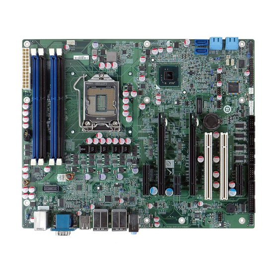
IMBA-C2160 ATX Motherboard 1.1 Introduction Figure 1-1: IMBA-C2160 The IMBA-C2160 is an ATX motherboard. It accepts a Socket LGA1155 Intel® Xeon® E3 or Intel® Core™ i3 quad/dual core processor and supports four 240-pin 1600/1333 MHz dual-channel DDR3 DIMM modules up to 32 GB. The IMBA-C2160 supports two GbE interfaces through the Intel®... -
Page 17: Features
IMBA-C2160 ATX Motherboard 1.2 Features Some of the IMBA-C2160 motherboard features are listed below: ATX form factor LGA1155 CPU socket Intel® C216 chipset Dual-channel DDR3 DIMMs support up to 32 GB Dual Intel® PCIe GbE (LAN1 with Intel® AMT 8.0 support) Supports USB 3.0 and SATA 6Gb/s Supports PCI Express Generation 3.0 at 8 GT/s I/O bandwidth High speed interface usage for two PCIe x8/two PCIe x4 add-on cards... -
Page 18: Connectors
IMBA-C2160 ATX Motherboard 1.3 Connectors The connectors on the IMBA-C2160 are shown in the figure below. Figure 1-2: Connectors Page 4... -
Page 19: Dimensions
IMBA-C2160 ATX Motherboard 1.4 Dimensions The main dimensions of the IMBA-C2160 are shown in the diagram below. Figure 1-3: IMBA-C2160 Dimensions (mm) Page 5... -
Page 20: Data Flow
IMBA-C2160 ATX Motherboard 1.5 Data Flow F igure 1-4 shows the data flow between the system chipset, the CPU and other components installed on the motherboard. Figure 1-4: Data Flow Diagram Page 6... -
Page 21: Technical Specifications
IMBA-C2160 ATX Motherboard 1.6 Technical Specifications The IMBA-C2160 technical specifications are listed below. Specification/Model IMBA-C2160 Form Factor LGA1155 Intel® Xeon® E3/Core™ i3 quad/dual core CPU CPU Supported Intel® C216 Chipset Memory Four 240-pin 1600/1333 MHz dual-channel ECC/non-ECC unbuffered DDR3 SDRAM DIMMs support (system max. 32 GB) Graphics Engine Intel®... - Page 22 IMBA-C2160 ATX Motherboard Specification/Model IMBA-C2160 One 4-pin CPU fan connector Fan Connectors Two 3-pin system fan connectors Front Panel One 14-pin header (power LED, HDD LED, speaker, power button, reset button) One 4-pin wafer connector Keyboard/Mouse One PS/2 keyboard/mouse port One internal keyboard and mouse connector via 6-pin wafer connector Parallel Port One parallel port via internal 26-pin box header...
-
Page 23: Table 1-1: Imba-C2160 Specifications
IMBA-C2160 ATX Motherboard Specification/Model IMBA-C2160 1200 g / 700 g Weight GW/NW Table 1-1: IMBA-C2160 Specifications Page 9... -
Page 24: Packing List
IMBA-C2160 ATX Motherboard Chapter Packing List Page 10... -
Page 25: Anti-Static Precautions
IMBA-C2160 ATX Motherboard 2.1 Anti-static Precautions WARNING! Static electricity can destroy certain electronics. Make sure to follow the ESD precautions to prevent damage to the product, and injury to the user. Make sure to adhere to the following guidelines: Wear an anti-static wristband: Wearing an anti-static wristband can prevent electrostatic discharge. -
Page 26: Packing List
IMBA-C2160 ATX Motherboard 2.3 Packing List NOTE: If any of the components listed in the checklist below are missing, do not proceed with the installation. Contact the IEI reseller or vendor the IMBA-C2160 was purchased from or contact an IEI sales representative directly by sending an email to sales@ieiworld.com. -
Page 27: Optional Items
IMBA-C2160 ATX Motherboard Quantity Item and Part Number Image Quick Installation Guide Table 2-1: Packing List 2.4 Optional Items The following are optional components which may be separately purchased: Item and Part Number Image Dual-port USB cable with bracket (P/N: 19800-003100-300-RS) SATA power cable (P/N: 32102-000100-200-RS) PS/2 KB/MS Y-cable with bracket (6-pin header) (220 mm) -
Page 28: Table 2-2: Optional Items
IMBA-C2160 ATX Motherboard Item and Part Number Image Parallel port cable (P/N: 19800-000049-RS) Dual RS-232 cable (230 mm) (P/N: 19800-000051-RS) 20-pin Infineon TPM module, S/W management tool, firmware v3.17 (P/N: TPM-IN01-R11) Table 2-2: Optional Items Page 14... -
Page 29: Connectors
IMBA-C2160 ATX Motherboard Chapter Connectors Page 15... -
Page 30: Peripheral Interface Connectors
IMBA-C2160 ATX Motherboard 3.1 Peripheral Interface Connectors This chapter details all the jumpers and connectors. 3.1.1 IMBA-C2160 Layout The figures below show all the connectors and jumpers. Figure 3-1: Connectors and Jumpers 3.1.2 Peripheral Interface Connectors The table below lists all the connectors on the board. Connector Type Label... - Page 31 IMBA-C2160 ATX Motherboard Connector Type Label Battery connector 2-pin wafer Battery holder CR2032 battery holder BAT1 CHA_DIMM1 CHA_DIMM2 DDR3 DIMM slots DDR3 DIMM slot CHB_DIMM1 CHB_DIMM2 Digital I/O connector 10-pin header DIO1 Fan connector (CPU) 4-pin wafer CPU_FAN1 SYS_FAN1, Fan connectors (system) 3-pin wafer SYS_FAN2 Front panel audio connector...
-
Page 32: External Interface Panel Connectors
IMBA-C2160 ATX Motherboard Connector Type Label SPI ROM connector 8-pin header JSPI1 TPM connector 20-pin header TPM1 USB1, USB2, USB 2.0 connectors 8-pin header USB3 Table 3-1: Peripheral Interface Connectors 3.1.3 External Interface Panel Connectors The table below lists the connectors on the external I/O panel. Connector Type Label... -
Page 33: Additional Power Connector
IMBA-C2160 ATX Motherboard Figure 3-2: +12V Power Connector Location Description VREG_12V VREG_12V Table 3-3: +12V Power Connector Pinouts 3.2.2 Additional Power Connector CN Label: ATXPWR1 4-pin connector CN Type: CN Location: See Figure 3-3 CN Pinouts: See Table 3-4 The additional power connector provides extra +12V and +5V power to the system. Page 19... -
Page 34: Atx Power Connector
IMBA-C2160 ATX Motherboard Figure 3-3: Additional Power Connector Location Description +12V Table 3-4: Additional Power Connector Pinouts 3.2.3 ATX Power Connector CN Label: ATX1 CN Type: 24-pin ATX CN Location: See Figure 3-5 CN Pinouts: See Table 3-6 The ATX power connector connects to an ATX power supply. Page 20... -
Page 35: Atx Power Connector
IMBA-C2160 ATX Motherboard Figure 3-4: ATX Power Connector Location Description Description +3.3V +3.3V +3.3V -12V PS_ON Power good 5VSB +12V +12V +3.3V Table 3-5: ATX Power Connector Pinouts 3.2.4 ATX Power Connector CN Label: ATX1 CN Type: 24-pin ATX CN Location: See Figure 3-5 CN Pinouts: See Table 3-6... -
Page 36: Figure 3-5: Atx Power Connector Pinout Location
IMBA-C2160 ATX Motherboard The ATX power connector connects to an ATX power supply. Figure 3-5: ATX Power Connector Pinout Location Description Description +3.3V +3.3V +3.3V -12V -IO_PSON PWRGD_PS V_5P0_A +12V +12V +3.3V Table 3-6: ATX Power Connector Pinouts Page 22... -
Page 37: Battery Connectors
IMBA-C2160 ATX Motherboard 3.2.5 Battery Connectors CAUTION: Risk of explosion if battery is replaced by an incorrect type. Only certified engineers should replace the on-board battery. Dispose of used batteries according to instructions and local regulations. CN Label: BAT1, BT2 CN Type: Battery holder and 2-pin wafer CN Location:... -
Page 38: Ddr3 Dimm Slots
IMBA-C2160 ATX Motherboard 3.2.6 DDR3 DIMM Slots CN Label: CHA_DIMM1, CHA_DIMM2, CHB_DIMM1, CHB_DIMM2 DDR3 DIMM slot CN Type: CN Location: F igure 3-7 The DIMM slots are for DDR3 DIMM memory modules. Figure 3-7: DDR3 DIMM Slot Locations 3.2.7 Digital I/O Connector CN Label: DIO1 CN Type:... -
Page 39: Fan Connector (Cpu)
IMBA-C2160 ATX Motherboard Figure 3-8: Digital I/O Connector Location Description Description Output 3 Output 2 Output 1 Output 0 Input 3 Input 2 Input 1 Input 0 Table 3-8: Digital I/O Connector Pinouts 3.2.8 Fan Connector (CPU) CN Label: CPU_FAN1 4-pin wafer CN Type: CN Location:... -
Page 40: Fan Connectors (System)
IMBA-C2160 ATX Motherboard Figure 3-9: CPU Fan Connector Location Description +12 V FANIO1 Table 3-9: CPU Fan Connector Pinouts 3.2.9 Fan Connectors (System) CN Label: SYS_FAN1, SYS_FAN2 CN Type: 3-pin wafer CN Location: See Figure 3-10 CN Pinouts: See Table 3-10 Each fan connector attaches to a cooling fan. -
Page 41: Front Panel Audio Connector
IMBA-C2160 ATX Motherboard Figure 3-10: System Fan Connector Locations Description FANIO +12 V (PWM) Table 3-10: System Fan Connector Pinouts 3.2.10 Front Panel Audio Connector CN Label: FP_AUDIO1 CN Type: 10-pin header CN Location: See Figure 3-11 See Table 3-11 CN Pinouts: This connector connects to speakers, a microphone and an audio input. -
Page 42: Front Panel Connector
IMBA-C2160 ATX Motherboard Figure 3-11: Front Panel Audio Connector Location Description Description LMIC2_L AUD GND LMIC2_R PRESENCE# LLINE2-R MIC2-JD F_SENSE LLINE2-L LINE2-JD Table 3-11: Front Panel Audio Connector Pinouts 3.2.11 Front Panel Connector CN Label: F_PANEL1 CN Type: 14-pin header CN Location: See Figure 3-12 See Table 3-12... -
Page 43: I2C Connector
IMBA-C2160 ATX Motherboard Figure 3-12: Front Panel Connector Location Function Description Function Description Power LED ACPILED Speaker Beep Power Power Button PWRBT_SW#_C PC Beep Reset HDD LED HDDLED EXTRST- HDDLED- Table 3-12: Front Panel Connector Pinouts 3.2.12 I2C Connector CN Label: I2C_1 CN Type: 4-pin wafer... -
Page 44: Keyboard/Mouse Connector
IMBA-C2160 ATX Motherboard Figure 3-13: I2C Connector Location Description +5V_DUAL PCH_GP38_PU PCH_GP39_PU Table 3-13: I2C Connector Pinouts 3.2.13 Keyboard/Mouse Connector CN Label: KB_MS1 CN Type: 6-pin wafer CN Location: See Figure 3-14 CN Pinouts: See Table 3-14 The keyboard/mouse connector connects to a PS/2 Y-cable that can be connected to a PS/2 keyboard and mouse. -
Page 45: Parallel Port Connector
IMBA-C2160 ATX Motherboard Figure 3-14: Keyboard/Mouse Connector Location Description VCC5_KBMS MSDATA MSCLK KBDATA KBCLK KBGND Table 3-14: Keyboard/Mouse Connector Pinouts 3.2.14 Parallel Port Connector CN Label: LPT1 CN Type: 26-pin box header CN Location: See Figure 3-15 CN Pinouts: See Table 3-15 The parallel port connector connects to a parallel port connector interface or some other parallel port device such as a printer. -
Page 46: Pci Slots
IMBA-C2160 ATX Motherboard Figure 3-15: Parallel Port Connector Location Description Description RSTROBE# RPD0 RPD1 RPD2 RPD4 RPD5 RPD6 RPD7 SIO_ACK# SIO_BUSY SIO_PE SIO_SLCT SIO_AFD# SIO_ERR# SIO_INIT# SIO_SLIN# Table 3-15: Parallel Port Connector Pinouts 3.2.15 PCI Slots CN Label: PCI1, PCI2 PCI Slot CN Type: CN Location:... -
Page 47: Pcie X1 Slot
IMBA-C2160 ATX Motherboard The PCI slot enables a PCI expansion module to be connected to the board. Figure 3-16: PCI Slot Locations 3.2.16 PCIe x1 Slot CN Label: PCIEX1_1 CN Type: PCIe x1 slot CN Location: See Figure 3-17 The PCIe x1 slot is for PCIe x1 expansion card. Figure 3-17: PCIe x1 Slot Location Page 33... -
Page 48: Pci Express X4 Slot
IMBA-C2160 ATX Motherboard 3.2.17 PCI Express x4 Slot CN Label: PCIEX4_1, PCIEX4_2 PCIe x4 slot CN Type: CN Location: See Figure 3-18 The PCIe x4 expansion card slots are for PCIe x4 expansion cards. Figure 3-18: PCIe x4 Slot Locations 3.2.18 PCI Express x8 Slot CN Label: PCIEX8_1... -
Page 49: Pci Express X16 Slot
IMBA-C2160 ATX Motherboard The PCIe x8 expansion card slot is for PCIe x8 expansion card. Figure 3-19: PCIe x8 Slot Location 3.2.19 PCI Express x16 Slot CN Label: PCIEX16_1 CN Type: PCIe x16 slot CN Location: See Figure 3-20 NOTE: When the Intel®... -
Page 50: Sata 3Gb/S Drive Connectors
IMBA-C2160 ATX Motherboard Figure 3-20: PCIe x16 Slot Location 3.2.20 SATA 3Gb/s Drive Connectors CN Label: SATA3, SATA4, SATA5, SATA6 CN Type: 7-pin SATA connector CN Location: See Figure 3-21 See Table 3-16 CN Pinouts: The SATA drive connectors can be connected to SATA drives and support up to 3Gb/s data transfer rate. -
Page 51: Sata 6Gb/S Drive Connectors
IMBA-C2160 ATX Motherboard Figure 3-21: SATA 3Gb/s Drive Connector Locations Description Description Table 3-16: SATA 3Gb/s Drive Connector Pinouts 3.2.21 SATA 6Gb/s Drive Connectors CN Label: SATA1, SATA2 CN Type: 7-pin SATA connector CN Location: See Figure 3-22 CN Pinouts: See Table 3-17 The SATA drive connectors can be connected to SATA drives and support up to 6Gb/s data transfer rate. -
Page 52: Serial Port Connector, Rs-422/485
IMBA-C2160 ATX Motherboard Figure 3-22: SATA 6Gb/s Drive Connector Locations Description Description Table 3-17: SATA 6Gb/s Drive Connector Pinouts 3.2.22 Serial Port Connector, RS-422/485 CN Label: COM4 4-pin wafer CN Type: CN Location: See Figure 3-23 CN Pinouts: See Table 3-18 This connector provides RS-422 or RS-485 communications. -
Page 53: Serial Port Connectors, Rs-232
IMBA-C2160 ATX Motherboard Figure 3-23: RS-422/485 Connector Location Description Description RXD422- TXD422+/TXD485+ RXD422+ TXD422-/TXD485- Table 3-18: RS-422/485 Connector Pinouts Use the optional RS-422/485 cable to connect to a serial device. The pinouts of the DB-9 connector are listed below. RS-422 Pinouts RS-485 Pinouts Table 3-19: DB-9 RS-422/485 Pinouts 3.2.23 Serial Port Connectors, RS-232... -
Page 54: Smbus Connector
IMBA-C2160 ATX Motherboard Figure 3-24: Serial Port Connector Locations Description Description -NDCD1 -NCTS1 -NDSR1 -NDTR1 NSIN1 -XRI1 -NRTS1 NSOUT1 Table 3-20: RS-232 Serial Port Connector Pinouts 3.2.24 SMBus Connector CN Label: SMBUS_1 4-pin wafer CN Type: CN Location: See Figure 3-25 CN Pinouts: See Table 3-21 The SMBus (System Management Bus) connector provides low-speed system... -
Page 55: Spi Rom Connector
IMBA-C2160 ATX Motherboard Figure 3-25: SMBus Connector Location Description +5V_DUAL SMBCLK SMBDATA Table 3-21: SMBus Connector Pinouts 3.2.25 SPI ROM Connector CN Label: JSPI1 8-pin header CN Type: CN Location: See Figure 3-26 CN Pinouts: See Table 3-22 The SPI connector is used to flash the BIOS. Page 41... -
Page 56: Tpm Connector
IMBA-C2160 ATX Motherboard Figure 3-26: SPI Connector Location Description Description +3.3V Table 3-22: SPI Connector Pinouts 3.2.26 TPM Connector CN Label: TPM1 CN Type: 20-pin header CN Location: See Figure 3-27 CN Pinouts: See Table 3-23 The TPM connector connects to a TPM module. Page 42... -
Page 57: Usb Connectors
IMBA-C2160 ATX Motherboard Figure 3-27: TPM Connector Location Description Description LCLK GND2 LERAME# LRESRT# LAD3 LAD2 LAD1 LAD0 GND3 SB3V SERIRQ GND1 GLKRUN# LPCPD# LDRQ# Table 3-23: TPM Connector Pinouts 3.2.27 USB Connectors CN Label: USB1, USB2, USB3 CN Type: 8-pin header CN Location: See Figure 3-28... -
Page 58: External Peripheral Interface Connector Panel
IMBA-C2160 ATX Motherboard Figure 3-28: USB Connector Pinout Locations Description Description DATA- DATA+ DATA+ DATA- Table 3-24: USB Port Connector Pinouts 3.3 External Peripheral Interface Connector Panel The figure below shows the external peripheral interface connector (EPIC) panel. The EPIC panel consists of the following: Page 44... -
Page 59: Audio Connector
IMBA-C2160 ATX Motherboard Figure 3-29: External Peripheral Interface Connector 3.3.1 Audio Connector CN Label: AUDIO_CV1 CN Type: Audio jack CN Location: See Figure 3-29 The audio jacks connect to external audio devices. Line In port (Light Blue): Connects a CD-ROM, DVD player, or other audio devices. -
Page 60: Ethernet And Usb 3.0 Connectors
IMBA-C2160 ATX Motherboard 3.3.2 Ethernet and USB 3.0 Connectors CN Label: LAN1_USB01, LAN2_USB23 RJ-45 and USB 3.0 ports CN Type: CN Location: See Figure 3-29 CN Pinouts: See Table 3-25 and Table 3-27 Each LAN connector connects to a local network. Description Description MDIA3-... -
Page 61: Ps/2 Keyboard/Mouse And Usb 2.0 Connectors
IMBA-C2160 ATX Motherboard Description Description STDA_SSRX_N STDA_SSRX_P GND_DRAIN STDA_SSTX_N STDA_SSTX_P Table 3-27: USB 3.0 Port Pinouts 3.3.3 PS/2 Keyboard/Mouse and USB 2.0 Connectors CN Label: K/M_USB1 PS/2 and USB 2.0 CN Type: CN Location: See Figure 3-29 CN Pinouts: See Figure 3-32, Table 3-28, Table 3-29 The keyboard and mouse connector is a standard PS/2 connector. -
Page 62: Serial Port And Vga Connector
IMBA-C2160 ATX Motherboard Description DATA - DATA + Table 3-29: USB 2.0 Port Pinouts 3.3.4 Serial Port and VGA Connector CN Label: VGACOM1 DB-9 and 15-pin VGA connectors CN Type: CN Location: See Figure 3-29 CN Pinouts: See Table 3-30, Figure 3-33, Table 3-31 and Figure 3-34 The serial port connects to a RS-232 serial communications device. -
Page 63: Usb 2.0 Connectors
IMBA-C2160 ATX Motherboard Figure 3-34: VGA Connector Description Description GREEN BLUE VCC / NC DDC DAT HSYNC VSYNC DDCCLK Table 3-31: VGA Connector Pinouts 3.3.5 USB 2.0 Connectors CN Label: CNUSB1 CN Type: USB 2.0 port See Figure 3-29 CN Location: CN Pinouts: See Table 3-25 The IMBA-C2160 has four external USB 2.0 ports. -
Page 64: Installation
IMBA-C2160 ATX Motherboard Chapter Installation Page 50... -
Page 65: Anti-Static Precautions
IMBA-C2160 ATX Motherboard 4.1 Anti-static Precautions WARNING: Failure to take ESD precautions during the installation of the IMBA-C2160 may result in permanent damage to the IMBA-C2160 and severe injury to the user. Electrostatic discharge (ESD) can cause serious damage to electronic components, including the IMBA-C2160. - Page 66 IMBA-C2160 ATX Motherboard WARNING: The installation instructions described in this manual should be carefully followed in order to prevent damage to the components and injury to the user. Before and during the installation please DO the following: Read the user manual: The user manual provides a complete description of the IMBA-C2160 installation instructions and configuration options.
-
Page 67: Socket Lga1155 Cpu Installation
IMBA-C2160 ATX Motherboard 4.2.1 Socket LGA1155 CPU Installation WARNING: CPUs are expensive and sensitive components. When installing the CPU please be careful not to damage it in anyway. Make sure the CPU is installed properly and ensure the correct cooling kit is properly installed. -
Page 68: Figure 4-2: Remove Protective Cover
IMBA-C2160 ATX Motherboard Figure 4-2: Remove Protective Cover Step 3: Inspect the CPU socket. Make sure there are no bent pins and make sure the socket contacts are free of foreign material. If any debris is found, remove it with compressed air. -
Page 69: Figure 4-3: Insert The Socket Lga1155 Cpu
IMBA-C2160 ATX Motherboard Figure 4-3: Insert the Socket LGA1155 CPU Step 8: Close the CPU socket. Close the load plate and pull the load lever back a little to have the load plate be able to secure to the knob. Engage the load lever by pushing it back to its original position (Figure 4-4). -
Page 70: Socket Lga1155 Cooling Kit Installation
IMBA-C2160 ATX Motherboard 4.2.2 Socket LGA1155 Cooling Kit Installation WARNING: DO NOT attempt to install a push-pin cooling fan. The pre-installed support bracket prevents the board from bending and is ONLY compatible with captive screw type cooling fans. The cooling kit can be bought from IEI. The cooling kit has a heatsink and fan. WARNING: Do not wipe off (accidentally or otherwise) the pre-sprayed layer of thermal paste on the bottom of the heat sink. -
Page 71: Dimm Installation
IMBA-C2160 ATX Motherboard Step 2: Place the cooling kit onto the socket LGA1155 CPU. Make sure the CPU cable can be properly routed when the cooling kit is installed. Step 3: Mount the cooling kit. Gently place the cooling kit on top of the CPU. Make sure the four threaded screws on the corners of the cooling kit properly pass through the holes of the cooling kit bracket. -
Page 72: Jumper Settings
IMBA-C2160 ATX Motherboard Step 3: Insert the DIMM. Once aligned, press down until the DIMM is properly seated. Clip the two handles into place. See Figure 4-6. Step 4: Removing a DIMM. To remove a DIMM, push both handles outward. The memory module is ejected by a mechanism in the socket.Step 0: 4.3 Jumper Settings... -
Page 73: At/Atx Power Select Jumper
IMBA-C2160 ATX Motherboard 4.3.1 AT/ATX Power Select Jumper Jumper Label: JATX_AT1 2-pin header Jumper Type: Jumper Settings: See Table 4-2 Jumper Location: See Figure 4-7 The AT/ATX Power Select jumper specifies the systems power mode as AT or ATX. Setting Description Closed ATX power (Default) -
Page 74: Flash Descriptor Security Override
IMBA-C2160 ATX Motherboard Setting Description Short 1-2 Normal (Default) Short 2-3 Clear BIOS Table 4-3: Clear BIOS Jumper Settings Figure 4-8: Clear BIOS Jumper Location 4.3.3 Flash Descriptor Security Override Jumper Label: J_FLASH1 3-pin header Jumper Type: Jumper Settings: See Table 4-4 Jumper Location: See Figure 4-9 The Flash Descriptor Security Override jumper specifies whether to override the flash... -
Page 75: Usb Power Select Jumpers
IMBA-C2160 ATX Motherboard Figure 4-9: Flash Descriptor Security Override Jumper Location 4.3.4 USB Power Select Jumpers Jumper Label: USB_PWR1, USB_PWR2, USB_PWR3, CNUSB1_PWR1, K/M_USB1_PWR1 Jumper Type: 3-pin header Jumper Settings: See Table 4-5 Jumper Location: See Figure 4-10 The USB Power Select jumper specifies the USB power. Setting Description Short 1-2... -
Page 76: Wake-On Lan Jumper
IMBA-C2160 ATX Motherboard Figure 4-10: USB Power Select Jumper Locations 4.3.5 Wake-on LAN Jumper CN Label: WOL_SEL1 3-pin header CN Type: CN Location: See Figure 4-11 CN Pinouts: See Table 4-6 The Wake-on LAN connector allows the user to enable or disable the Wake-on LAN (WOL) function. -
Page 77: Internal Peripheral Device Connections
IMBA-C2160 ATX Motherboard Figure 4-11: Wake-on LAN Connector Pinout Location 4.4 Internal Peripheral Device Connections This section outlines the installation of peripheral devices to the onboard connectors. 4.4.1 SATA Drive Connection The IMBA-C2160 is shipped with four SATA drive cables. To connect the SATA drives to the connectors, please follow the steps below. -
Page 78: Figure 4-12: Sata Drive Cable Connection
IMBA-C2160 ATX Motherboard Figure 4-12: SATA Drive Cable Connection Step 3: Connect the cable to the SATA disk. Connect the connector on the other end of the cable to the connector at the back of the SATA drive. See Figure 4-13. Step 4: Connect the SATA power cable (optional). -
Page 79: External Peripheral Interface Connection
IMBA-C2160 ATX Motherboard 4.5 External Peripheral Interface Connection This section describes connecting devices to the external connectors on the IMBA-C2160. 4.5.1 Audio Connector The audio jacks on the external audio connector enable the IMBA-C2160 to be connected to a stereo sound setup. Each jack supports both input and output. When connecting a device, the High Definition Audio utility will automatically detect input or output. -
Page 80: Lan Connection
IMBA-C2160 ATX Motherboard 4.5.2 LAN Connection There are two external RJ-45 LAN connectors. The RJ-45 connectors enable connection to an external network. To connect a LAN cable with an RJ-45 connector, please follow the instructions below. Step 1: Locate the RJ-45 connectors. The locations of the USB connectors are shown in Chapter 3. -
Page 81: Serial Device Connection
IMBA-C2160 ATX Motherboard Step 1: Locate the PS/2 connector. The location of the PS/2 connector is shown in Chapter 3. Step 2: Align the PS/2 connector. Align the PS/2 connector on the keyboard/mouse cable with the PS/2 connector on the external peripheral interface. Step 3: Insert the PS/2 connector. -
Page 82: Usb Connection (Dual Connector)
IMBA-C2160 ATX Motherboard Figure 4-17: Serial Device Connection Step 3: Secure the connector. Secure the serial device connector to the external interface by tightening the two retention screws on either side of the connector. Step 0: 4.5.5 USB Connection (Dual Connector) The external USB Series "A"... -
Page 83: Vga Monitor Connection
IMBA-C2160 ATX Motherboard Figure 4-18: USB Connection 4.5.6 VGA Monitor Connection The IMBA-C2160 has a single female DB-15 connector on the external peripheral interface panel. The DB-15 connector is connected to a CRT or VGA monitor. To connect a monitor to the IMBA-C2160, please follow the instructions below. Step 1: Locate the female DB-15 connector. -
Page 84: Intel ® Amt Setup Procedure
IMBA-C2160 ATX Motherboard Figure 4-19: VGA Connection Step 4: Secure the connector. Secure the DB-15 VGA connector from the VGA monitor to the external interface by tightening the two retention screws on either side of the connector. Step 0: ® 4.6 Intel AMT Setup Procedure The IMBA-C2160 is featured with the Intel®... - Page 85 IMBA-C2160 ATX Motherboard process. Enter the Intel® current ME password as it requires (the Intel® default password is admin). NOTE: To change the password, enter a new password following the strong password rule (containing at least one upper case letter, one lower case letter, one digit and one special character, and be at least eight characters).
-
Page 86: Bios
IMBA-C2160 ATX Motherboard Chapter BIOS Page 72... -
Page 87: Introduction
IMBA-C2160 ATX Motherboard 5.1 Introduction The BIOS is programmed onto the BIOS chip. The BIOS setup program allows changes to certain system settings. This chapter outlines the options that can be changed. NOTE: Some of the BIOS options may vary throughout the life cycle of the product and are subject to change without prior notice. -
Page 88: Getting Help
IMBA-C2160 ATX Motherboard Function Decrease the numeric value or make changes Page Up key Move to the next page Page Dn key Move to the previous page Esc key Main Menu – Quit and not save changes into CMOS Status Page Setup Menu and Option Page Setup Menu -- Exit current page and return to Main Menu General help, only for Status Page Setup Menu and Option Page Setup Menu... - Page 89 IMBA-C2160 ATX Motherboard Security – Sets User and Supervisor Passwords. Save & Exit – Selects exit options and loads default settings The following sections completely describe the configuration options found in the menu items at the top of the BIOS screen and listed above. Page 75...
-
Page 90: Main
IMBA-C2160 ATX Motherboard 5.2 Main The Main BIOS menu (BIOS Menu 1) appears when the BIOS Setup program is entered. The Main menu gives an overview of the basic system information. Aptio Setup Utility – Copyright (C) 2011 American Megatrends, Inc. Main Advanced Chipset... -
Page 91: Advanced
IMBA-C2160 ATX Motherboard The Main menu lists the following system details: BIOS Information Processor Information Memory Information PCH Information SPI Clock Frequency The Main menu has two user configurable fields: System Date [xx/xx/xx] Use the System Date option to set the system date. Manually enter the day, month and year. -
Page 92: Acpi Settings
IMBA-C2160 ATX Motherboard Aptio Setup Utility – Copyright (C) 2011 American Megatrends, Inc. Main Advanced Chipset Boot Security Save & Exit > ACPI Settings System ACPI Parameters > RTC Wake Settings > Trusted Computing > CPU Configuration > SATA Configuration ---------------------- >... -
Page 93: Rtc Wake Settings
IMBA-C2160 ATX Motherboard ACPI Sleep State [S1 only (CPU Stop Clock)] Use the ACPI Sleep State option to specify the sleep state the system enters when it is not being used. S1 only (CPU Stop The system enters S1(POS) sleep state. The EFAULT Clock) system appears off. -
Page 94: Trusted Computing
IMBA-C2160 ATX Motherboard Wake System with Fixed Time [Disabled] Use the Wake System with Fixed Time option to specify the time the system should be roused from a suspended state. Disabled The real time clock (RTC) cannot generate a wake EFAULT event If selected, the following appears with values that... -
Page 95: Cpu Configuration
IMBA-C2160 ATX Motherboard Aptio Setup Utility – Copyright (C) 2011 American Megatrends, Inc. Advanced Configuration Enables or Disables BIOS Security Device Support [Disable] support for security device. O.S. will not Current Status Information show Security Device. NO Security Device Found TCG EFI protocol and INT1A interface will not be available. -
Page 96: Bios Menu 6: Cpu Configuration
IMBA-C2160 ATX Motherboard Aptio Setup Utility – Copyright (C) 2011 American Megatrends, Inc. Advanced CPU Configuration Enabled for Windows XP and Linux (OS optimized Intel(R) Xeon(R) CPU E3-1275 V2 @ 3.50GHz for Hyper-Threading CPU Signature 306a9 Technology) and Disabled Microcode Patch for other OS (OS not Max CPU Speed 3500 MHz... - Page 97 IMBA-C2160 ATX Motherboard L1 Data Cache: Lists the amount of data storage space on the L1 cache. L1 Code Cache: Lists the amount of code storage space on the L1 cache. L2 Cache: Lists the amount of storage space on the L2 cache. L3 Cache: Lists the amount of storage space on the L3 cache.
-
Page 98: Sata Configuration
IMBA-C2160 ATX Motherboard 5.3.5 SATA Configuration Use the SATA Configuration menu (BIOS Menu 7) to change and/or set the configuration of the SATA devices installed in the system. Aptio Setup Utility – Copyright (C) 2011 American Megatrends, Inc. Advanced SATA Controller(s) [Enabled] Enable or disable SATA SATA Mode Selection... -
Page 99: Intel(R) Rapid Start Technology
IMBA-C2160 ATX Motherboard 5.3.6 Intel(R) Rapid Start Technology Use the Intel(R) Rapid Start Technology (BIOS Menu 8) menu to configure Intel® Rapid Start Technology support. Aptio Setup Utility – Copyright (C) 2011 American Megatrends, Inc. Advanced Intel(R) Rapid Start Technology [Disabled] --------------------- : Select Screen... -
Page 100: Intel Txt(Lt) Configuration
IMBA-C2160 ATX Motherboard 5.3.7 Intel TXT(LT) Configuration Use the Intel TXT(LT) Configuration (BIOS Menu 9) menu to configure Intel Trusted Execution Technology support. Aptio Setup Utility – Copyright (C) 2011 American Megatrends, Inc. Advanced Intel Trusted Execution Technology Configuration Intel TXT support only can be enabled/disabled if SMX is enabled. -
Page 101: Amt Configuration
IMBA-C2160 ATX Motherboard 5.3.8 AMT Configuration The AMT Configuration menu (BIOS Menu 10) allows the advanced power management options to be configured. Aptio Setup Utility – Copyright (C) 2011 American Megatrends, Inc. Advanced Intel AMT [Enabled] Enable/Disable Intel (R) Un-Configure ME [Disabled] Active Management Technology BIOS... -
Page 102: Usb Configuration
IMBA-C2160 ATX Motherboard 5.3.9 USB Configuration Use the USB Configuration menu (BIOS Menu 11) to read USB configuration information and configure the USB settings. Aptio Setup Utility – Copyright (C) 2011 American Megatrends, Inc. Advanced USB Configuration Enables Legacy USB support. -
Page 103: F81866 Super Io Configuration
IMBA-C2160 ATX Motherboard 5.3.10 F81866 Super IO Configuration Use the F81866 Super IO Configuration menu (BIOS Menu 12) to set or change the configurations for the parallel port and serial ports. Aptio Setup Utility – Copyright (C) 2011 American Megatrends, Inc. Advanced F81866 Super IO Configuration Set Parameters of Serial... - Page 104 IMBA-C2160 ATX Motherboard 5.3.10.1.1 Serial Port 1 Configuration Serial Port [Enabled] Use the Serial Port option to enable or disable the serial port. Disabled Disable the serial port Enabled Enable the serial port EFAULT Change Settings [Auto] Use the Change Settings option to change the serial port IO port address and interrupt address.
- Page 105 IMBA-C2160 ATX Motherboard Change Settings [Auto] Use the Change Settings option to change the serial port IO port address and interrupt address. Auto The serial port IO port address and interrupt address EFAULT are automatically detected. Serial Port I/O port address is 2F8h and the interrupt IO=2F8h;...
- Page 106 IMBA-C2160 ATX Motherboard IO=3E8h; Serial Port I/O port address is 3E8h and the interrupt IRQ=10 address is IRQ10 Serial Port I/O port address is 3E8h and the interrupt IO=3E8h; address is IRQ10, 11 IRQ=10, 11 IO=2E8h; Serial Port I/O port address is 2E8h and the interrupt IRQ=10, 11 address is IRQ10, 11 IO=2D0h;...
- Page 107 IMBA-C2160 ATX Motherboard IO=2D0h; Serial Port I/O port address is 2D0h and the interrupt IRQ=10, 11 address is IRQ10, 11 Serial Port I/O port address is 2D8h and the interrupt IO=2D8h; address is IRQ10, 11 IRQ=10, 11 5.3.10.1.5 Serial Port 5 Configuration Serial Port [Enabled] Use the Serial Port option to enable or disable the serial port.
- Page 108 IMBA-C2160 ATX Motherboard 5.3.10.1.6 Serial Port 6 Configuration Serial Port [Enabled] Use the Serial Port option to enable or disable the serial port. Disabled Disable the serial port Enable the serial port Enabled EFAULT Change Settings [Auto] Use the Change Settings option to change the serial port IO port address and interrupt address.
-
Page 109: Parallel Port Configuration
IMBA-C2160 ATX Motherboard 5.3.10.2 Parallel Port Configuration Use the Parallel Port Configuration menu (BIOS Menu 14) to configure the parallel port. Aptio Setup Utility – Copyright (C) 2011 American Megatrends, Inc. Advanced Parallel Port Configuration Enable or Disable Parallel Port (LPT/LPTE) Parallel Port [Enabled] Device Settings... -
Page 110: F81866 H/W Monitor
IMBA-C2160 ATX Motherboard IO=278h; Parallel Port I/O port address is 278h and the IRQ=5, 7 interrupt address is IRQ5, 7 Parallel Port I/O port address is 3BCh and the IO=3BCh; interrupt address is IRQ5, 7 IRQ=5, 7 Device Mode [STD Printer Mode] Use the Device Mode option to select the mode the parallel port operates in. -
Page 111: Bios Menu 15: H/W Monitor
IMBA-C2160 ATX Motherboard Aptio Setup Utility – Copyright (C) 2011 American Megatrends, Inc. Advanced PC Health Status Smart Fan Mode Select > Smart Fan Mode Configuration CPU temperature :+23 C Accuracy: 1. -5~ +10 degree around 100 degree. 2. -10~ +15 degree around 50 degree. --------------------- System Temperature :+33 C... -
Page 112: Smart Fan Mode Configuration
IMBA-C2160 ATX Motherboard 5.3.11.1 Smart Fan Mode Configuration Use the Smart Fan Mode Configuration submenu (BIOS Menu 16) to configure fan temperature and speed settings. Aptio Setup Utility – Copyright (C) 2011 American Megatrends, Inc. Advanced Smart Fan Mode Configuration Smart Fan Mode Select CPU_FAN1 Smart Fan Control [Auto Duty-Cycle Mode]... - Page 113 IMBA-C2160 ATX Motherboard SYS_FAN1 Smart Fan Control [Auto Duty-Cycle Mode] Use the SYS_FAN1 Smart Fan Control option to configure the System Smart Fan (SYS_FAN1). Manual Duty The fan spins at the speed set in Manual by Duty Mode Cycle settings The fan adjusts its speed using Auto by Auto Duty-Cycle EFAULT...
-
Page 114: Serial Port Console Redirection
IMBA-C2160 ATX Motherboard 5.3.12 Serial Port Console Redirection The Serial Port Console Redirection menu (BIOS Menu 17) allows the console redirection options to be configured. Console redirection allows users to maintain a system remotely by re-directing keyboard input and text output through the serial port. Aptio Setup Utility –... - Page 115 IMBA-C2160 ATX Motherboard VT100 The target terminal type is VT100 The target terminal type is VT100+ VT100+ VT-UTF8 The target terminal type is VT-UTF8 ANSI The target terminal type is ANSI EFAULT Bits per second [115200] Use the Bits per second option to specify the serial port transmission speed. The speed must match the other side.
-
Page 116: Iei Feature
IMBA-C2160 ATX Motherboard Mark The parity bit is always 1. This option does not provide error detection. The parity bit is always 0. This option does not Space provide error detection. Stop Bits [1] Use the Stop Bits option to specify the number of stop bits used to indicate the end of a serial data packet. -
Page 117: Chipset
IMBA-C2160 ATX Motherboard Auto Recovery Function [Disabled] Use the Auto Recovery Function BIOS option to enable or disable the auto recovery function of the IEI One Key Recovery. Disabled Auto recovery function disabled EFAULT Auto recovery function enabled Enabled 5.4 Chipset Use the Chipset menu (BIOS Menu 19) to access the Hostbridge and Southbridge configuration menus. -
Page 118: Pch-Io Configuration
IMBA-C2160 ATX Motherboard 5.4.1 PCH-IO Configuration Use the PCH-IO Configuration menu (BIOS Menu 20) to configure the PCH parameters. Aptio Setup Utility – Copyright (C) 2011 American Megatrends, Inc. Chipset Auto Power Button Status [Disabled] Select AC power state when power is re-applied Restore AC Power Loss [Last State] after a power failure. -
Page 119: Pch Azalia Configuration
IMBA-C2160 ATX Motherboard 5.4.1.1 PCH Azalia Configuration Use the PCH Azalia Configuration menu (BIOS Menu 21) to configure the PCH Azalia settings. Aptio Setup Utility – Copyright (C) 2011 American Megatrends, Inc. Main Advanced Chipset Boot Security Save & Exit PCH Azalia Configuration Control Detection of the Azalia device. -
Page 120: System Agent (Sa) Configuration
IMBA-C2160 ATX Motherboard 5.4.2 System Agent (SA) Configuration Use the System Agent (SA) Configuration menu (BIOS Menu 22) to configure the System Agent (SA) parameters. Aptio Setup Utility – Copyright (C) 2011 American Megatrends, Inc. Chipset VT-d [Disabled] Check to enable VT-d function on MCH. -
Page 121: Bios Menu 23: Graphics Configuration
IMBA-C2160 ATX Motherboard Aptio Setup Utility – Copyright (C) 2011 American Megatrends, Inc. Chipset Graphics Configuration Select which of IGFX/PEG/PCI Graphics Primary Display [Auto] device should be Primary DVMT Pre-Allocated [128M] Display Or select SG for DVMT Total Gfx Mem [MAX] Switchable Gfx. -
Page 122: Bios Menu 24: Lcd Control
IMBA-C2160 ATX Motherboard DVMT Total Gfx Mem [MAX] Use the DVMT Total Gfx Mem option to select DVMT5.0 total graphic memory size used by the internal graphic device. The following options are available: 128M 256M Default 5.4.2.1.1 LCD Control Aptio Setup Utility – Copyright (C) 2011 American Megatrends, Inc. Chipset LCD Control Select the Video Device... -
Page 123: Nb Pcie Configuration
IMBA-C2160 ATX Motherboard 5.4.2.2 NB PCIe Configuration Aptio Setup Utility – Copyright (C) 2011 American Megatrends, Inc. Chipset NB PCIe Configuration Configure PEG0 B0:D1:F0 PEG0 Not Present Gen1-Gen3 PEG0 – Gen X [Auto] ---------------------- : Select Screen ↑ ↓: Select Item Enter: Select +/-: Change Opt. -
Page 124: Memory Configuration
IMBA-C2160 ATX Motherboard 5.4.2.3 Memory Configuration Use the Memory Configuration submenu (BIOS Menu 26) to view memory information. Aptio Setup Utility – Copyright (C) 2011 American Megatrends, Inc. Chipset Memory Information Total Memory 2048 MB (DDR3) CHA_DIMM1 2048 MB (DDR3) CHA_DIMM2 Not Present CHB_DIMM1... - Page 125 IMBA-C2160 ATX Motherboard Bootup NumLock State [On] Use the Bootup NumLock State BIOS option to specify if the number lock setting must be modified during boot up. Allows the Number Lock on the keyboard to be EFAULT enabled automatically when the computer system boots up.
-
Page 126: Security
IMBA-C2160 ATX Motherboard Launch PXE OpROM [Disabled] Use the Launch PXE OpROM option to enable or disable boot option for legacy network devices. Disabled Ignore all PXE Option ROMs EFAULT Load PXE Option ROMs. Enabled UEFI Boot [Disabled] Use the UEFI Boot option to enable or disable to boot from the UEFI devices. Enabled Boot from UEFI devices is enabled. -
Page 127: Save & Exit
IMBA-C2160 ATX Motherboard User Password Use the User Password to set or change a user password. 5.7 Save & Exit Use the Save & Exit menu (BIOS Menu 29) to load default BIOS values, optimal failsafe values and to save configuration changes. Aptio Setup Utility –... - Page 128 IMBA-C2160 ATX Motherboard Save as User Defaults Use the Save as User Defaults option to save the changes done so far as user defaults. Restore User Defaults Use the Restore User Defaults option to restore the user defaults to all the setup options. Page 114...
-
Page 129: Software Drivers
IMBA-C2160 ATX Motherboard Chapter Software Drivers Page 115... -
Page 130: Available Software Drivers
IMBA-C2160 ATX Motherboard 6.1 Available Software Drivers NOTE: The content of the CD may vary throughout the life cycle of the product and is subject to change without prior notice. Visit the IEI website or contact technical support for the latest updates. The following drivers can be installed on the system: Chipset Graphics... -
Page 131: Figure 6-1: Introduction Screen
IMBA-C2160 ATX Motherboard Step 2: The driver main menu appears (Figure 6-1). Figure 6-1: Introduction Screen Step 3: Click IMBA-C2160. Step 4: A new screen with a list of available drivers appears (Figure 6-2). Figure 6-2: Available Drivers Step 5: Install all of the necessary drivers in this menu. -
Page 132: Chipset Driver Installation
IMBA-C2160 ATX Motherboard 6.3 Chipset Driver Installation To install the chipset driver, please do the following. Step 1: Access the driver list. (See Section 6.2) Step 2: Click “Chipset”. Step 3: Locate the setup file and double click on it. Step 4: When the setup files are completely extracted, the Welcome Screen in Figure 6-3 appears. -
Page 133: Figure 6-4: Chipset Driver License Agreement
IMBA-C2160 ATX Motherboard Figure 6-4: Chipset Driver License Agreement Step 9: The Read Me file in Figure 6-5 appears. Step 10: Click Next to continue. Figure 6-5: Chipset Driver Read Me File Page 119... -
Page 134: Figure 6-6: Chipset Driver Setup Operations
IMBA-C2160 ATX Motherboard Step 11: Setup Operations are performed as shown in Figure 6-6. Step 12: Once the Setup Operations are complete, click Next to continue. Figure 6-6: Chipset Driver Setup Operations Step 13: The Finish screen in Figure 6-7 appears. Step 14: Select “Yes, I want to restart this computer now”... -
Page 135: Graphics Driver Installation
IMBA-C2160 ATX Motherboard Figure 6-7: Chipset Driver Installation Finish Screen 6.4 Graphics Driver Installation To install the Graphics driver, please do the following. Step 1: Access the driver list. (See Section 6.2) Step 2: Click “Graphics” and select the folder which corresponds to the operating system. -
Page 136: Figure 6-8: Graphics Driver Welcome Screen
IMBA-C2160 ATX Motherboard Figure 6-8: Graphics Driver Welcome Screen Step 6: The License Agreement in Figure 6-9 appears. Step 7: Click Yes to accept the agreement and continue. Figure 6-9: Graphics Driver License Agreement Step 8: Setup Operations are performed as shown in Figure 6-10. Page 122... -
Page 137: Figure 6-10: Graphics Driver Setup Operations
IMBA-C2160 ATX Motherboard Step 9: Once the Setup Operations are complete, click Next to continue. Figure 6-10: Graphics Driver Setup Operations Step 10: The Finish screen in Figure 6-11 appears. Step 11: Select “Yes, I want to restart this computer now” and click Finish.Step 0: Figure 6-11: Graphics Driver Installation Finish Screen Page 123... -
Page 138: Lan Driver Installation
IMBA-C2160 ATX Motherboard 6.5 LAN Driver Installation Step 1: Right-click the Computer button from the start menu and select Properties. (Figure 6-12). Figure 6-12: Windows Control Panel Step 2: The system control panel window in Figure 6-13 appears. Step 3: Click the Device Manager link (Figure 6-13). -
Page 139: Figure 6-14: Device Manager List
IMBA-C2160 ATX Motherboard Step 4: A list of system hardware devices appears (Figure 6-14). Step 5: Right-click the Ethernet Controller that has question marks next to it (this means Windows does not recognize the device). Step 6: Select Update Driver Software. Figure 6-14: Device Manager List Step 7: The Update Driver Software Window appears (Figure 6-15). -
Page 140: Figure 6-15: Update Driver Software Window
IMBA-C2160 ATX Motherboard Figure 6-15: Update Driver Software Window Step 8: Select “Browse my computer for driver software” to continue. Step 9: Click Browse to select “X:\3-LAN” directory in the Locate File window, where “X:\” is the system CD drive. (Figure 6-16). Figure 6-16: Locate Driver Files Step 10: Click N... -
Page 141: Figure 6-17: Lan Driver Installation
IMBA-C2160 ATX Motherboard Figure 6-17: LAN Driver Installation Step 12: The Finish screen in Figure 6-18 appears. Click Close to exit. Step 0: Figure 6-18: LAN Driver Installation Complete Page 127... -
Page 142: Audio Driver Installation
IMBA-C2160 ATX Motherboard 6.6 Audio Driver Installation To install the audio driver, please do the following. Step 1: Access the driver list. (See Section 6.2) Step 2: Click “Audio” and select the folder which corresponds to the operating system. Step 3: Double click the setup file. -
Page 143: Figure 6-20: Audio Driver Software Configuration
IMBA-C2160 ATX Motherboard Figure 6-20: Audio Driver Software Configuration Step 8: After the driver installation process is complete, a confirmation screen appears (Figure 6-21). Figure 6-21: Restart the Computer Page 129... -
Page 144: Intel® Rapid Storage Technology Driver Installation
IMBA-C2160 ATX Motherboard Step 9: The confirmation screen offers the option of restarting the computer now or later. For the settings to take effect, the computer must be restarted. Click F INISH restart the computer. Step 0: 6.7 Intel® Rapid Storage Technology Driver Installation To install the Intel®... -
Page 145: Figure 6-23: Sata Raid Driver License Agreement
IMBA-C2160 ATX Motherboard Figure 6-23: SATA RAID Driver License Agreement Step 9: The Read Me file in Figure 6-24 appears. Step 10: Click Next to continue. Figure 6-24: SATA RAID Driver Read Me File Step 11: Setup Operations are performed as shown in Figure 6-25. Step 12: Once the Setup Operations are complete, click Next to continue. -
Page 146: Figure 6-25: Sata Raid Driver Setup Operations
IMBA-C2160 ATX Motherboard Figure 6-25: SATA RAID Driver Setup Operations Step 13: The Finish screen in Figure 6-26 appears. Step 14: Select “Yes, I want to restart this computer now” and click Finish.Step 0: Figure 6-26: SATA RAID Driver Installation Finish Screen Page 132... -
Page 147: Usb 3.0 Driver Installation
IMBA-C2160 ATX Motherboard 6.8 USB 3.0 Driver Installation WARNING: Do not run this driver’s installer (Setup.exe) from a USB storage device (ie. external USB hard drive or USB thumb drive). For proper installation, please copy driver files to a local hard drive folder and run from there. -
Page 148: Figure 6-28: Usb 3.0 Driver License Agreement
IMBA-C2160 ATX Motherboard Step 8: Click Yes to continue. Figure 6-28: USB 3.0 Driver License Agreement Step 9: The Read Me file in Figure 6-29 appears. Step 10: Click Next to continue. Figure 6-29: USB 3.0 Driver Read Me File Step 11: Setup Operations are performed as shown in Figure 6-30. -
Page 149: Figure 6-30: Usb 3.0 Driver Setup Operations
IMBA-C2160 ATX Motherboard Figure 6-30: USB 3.0 Driver Setup Operations Step 13: The Finish screen in Figure 6-31 appears. Step 14: Select “Yes, I want to restart this computer now” and click Finish.Step 0: Figure 6-31: USB 3.0 Driver Installation Finish Screen Page 135... -
Page 150: Intel® Amt Driver Installation
IMBA-C2160 ATX Motherboard 6.9 Intel® AMT Driver Installation The package of the Intel® AMT components includes Intel® Management Engine Interface (Intel® ME Interface) Intel® Dynamic Application Loader Intel® Identity Protection Technology (Intel® IPT) Serial Over LAN (SOL) Intel® Manageability Engine Firmware Recovery Agent Intel®... -
Page 151: Figure 6-32: Intel® Me Driver Welcome Screen
IMBA-C2160 ATX Motherboard Figure 6-32: Intel® ME Driver Welcome Screen Step 6: The license agreement in Figure 6-33 appears. Step 7: Read the License Agreement. Step 8: Click Yes to continue. Figure 6-33: Intel® ME Driver License Agreement Step 9: Setup Operations are performed as shown in Figure 6-34. -
Page 152: Figure 6-34: Intel® Me Driver Setup Operations
IMBA-C2160 ATX Motherboard Figure 6-34: Intel® ME Driver Setup Operations Step 11: The Finish screen in Figure 6-35 appears. Step 12: Select “Yes, I want to restart this computer now” and click Finish.Step 0: Figure 6-35: Intel® ME Driver Installation Finish Screen Page 138... -
Page 153: Abios Options
IMBA-C2160 ATX Motherboard Appendix BIOS Options Page 139... - Page 154 IMBA-C2160 ATX Motherboard Below is a list of BIOS configuration options in the BIOS chapter. System Date [xx/xx/xx] ......................77 System Time [xx:xx:xx] .......................77 ACPI Sleep State [S1 only (CPU Stop Clock)]..............79 Wake System with Fixed Time [Disabled] .................80 ...
- Page 155 IMBA-C2160 ATX Motherboard Console Redirection [Disabled] ..................100 Terminal Type [ANSI]......................100 Bits per second [115200]....................101 Data Bits [8] ........................101 Parity [None]........................101 Stop Bits [1] ........................102 Auto Recovery Function [Disabled]................103 ...
-
Page 156: B Terminology
IMBA-C2160 ATX Motherboard Appendix Terminology Page 142... - Page 157 IMBA-C2160 ATX Motherboard AC ’97 Audio Codec 97 (AC’97) refers to a codec standard developed by Intel® in 1997. ACPI Advanced Configuration and Power Interface (ACPI) is an OS-directed configuration, power management, and thermal management interface. AHCI Advanced Host Controller Interface (AHCI) is a SATA Host controller register-level interface.
- Page 158 IMBA-C2160 ATX Motherboard DIMM Dual Inline Memory Modules are a type of RAM that offer a 64-bit data bus and have separate electrical contacts on each side of the module. The digital inputs and digital outputs are general control signals that control the on/off circuit of external devices or TTL devices.
- Page 159 IMBA-C2160 ATX Motherboard LVDS Low-voltage differential signaling (LVDS) is a dual-wire, high-speed differential electrical signaling system commonly used to connect LCD displays to a computer. POST The Power-on Self Test (POST) is the pre-boot actions the system performs when the system is turned-on. Random Access Memory (RAM) is volatile memory that loses data when power is lost.
-
Page 160: C Digital I/O Interface
IMBA-C2160 ATX Motherboard Appendix Digital I/O Interface Page 146... -
Page 161: Introduction
IMBA-C2160 ATX Motherboard C.1 Introduction The DIO connector on the IMBA-C2160 is interfaced to GPIO ports on the Super I/O chipset. The DIO has both 4-bit digital inputs and 4-bit digital outputs. The digital inputs and digital outputs are generally control signals that control the on/off circuit of external devices or TTL devices. -
Page 162: Assembly Language Samples
IMBA-C2160 ATX Motherboard C.3 Assembly Language Samples C.3.1 Enable the DIO Input Function The BIOS interrupt call INT 15H controls the digital I/O. An assembly program to enable digital I/O input functions is listed below. Sets the digital port as input AX, 6F08H Initiates the INT 15H BIOS call C.3.2 Enable the DIO Output Function... -
Page 163: D Watchdog Timer
IMBA-C2160 ATX Motherboard Appendix Watchdog Timer Page 149... - Page 164 IMBA-C2160 ATX Motherboard NOTE: The following discussion applies to DOS environment. Contact IEI support or visit the IEI website for specific drivers for other operating systems. The Watchdog Timer is provided to ensure that standalone systems can always recover from catastrophic conditions that cause the CPU to crash. This condition may have occurred by external EMIs or a software bug.
- Page 165 IMBA-C2160 ATX Motherboard NOTE: When exiting a program it is necessary to disable the Watchdog Timer, otherwise the system resets. EXAMPLE PROGRAM: ; INITIAL TIMER PERIOD COUNTER W_LOOP: AX, 6F02H ;setting the time-out value BL, 30 ;time-out value is 48 seconds ;...
-
Page 166: E Intel® Matrix Storage Manager
IMBA-C2160 ATX Motherboard Appendix Intel® Matrix Storage Manager Page 152... -
Page 167: Introduction
IMBA-C2160 ATX Motherboard E.1 Introduction The IMBA-C2160 can provide data protection for serial ATA (SATA) disks via the Intel® Matrix Storage Manager using one of three fault-tolerant RAID levels: RAID 1, 5 or 10. When using two hard drives, matrix RAID allows RAID 0 and RAID 1 functions to be combined, where critical files can be stored on RAID 1, and RAID 0 can be used for non-critical items such as software. -
Page 168: Features And Benefits
IMBA-C2160 ATX Motherboard CAUTION! Do not accidentally disconnect the SATA drive cables. Carefully route the cables within the chassis to avoid system down time. E.2 Features and Benefits Supports RAID levels 0, 1, 5 and 10 Supports connectivity to two or more disk drives Supported Operating Systems include: Windows XP, Windows Server 2003, Windows Server 2008, Windows Vista and Windows 7 E.3 Accessing the Intel®... -
Page 169: Installing The Operating System To The Raid Array
IMBA-C2160 ATX Motherboard appear during the POST. Refer to the applicable BIOS configuration section in this user manual. Step 4: Save and Exit BIOS. After the SATA support option is enabled, save and exit the BIOS. Step 5: Reboot the system. Reboot the system after saving and exiting the BIOS. Step 6: Press Ctrl+I. -
Page 170: F Hazardous Materials Disclosure
IMBA-C2160 ATX Motherboard Appendix Hazardous Materials Disclosure Page 156... -
Page 171: Hazardous Materials Disclosure Table For Ipb Products Certified As Rohs Compliant Under 2002/95/Ec Without Mercury
IMBA-C2160 ATX Motherboard F.1 Hazardous Materials Disclosure Table for IPB Products Certified as RoHS Compliant Under 2002/95/EC Without Mercury The details provided in this appendix are to ensure that the product is compliant with the Peoples Republic of China (China) RoHS standards. The table below acknowledges the presences of small quantities of certain materials in the product, and is applicable to China RoHS only. - Page 172 IMBA-C2160 ATX Motherboard Part Name Toxic or Hazardous Substances and Elements Lead Mercury Cadmium Hexavalent Polybrominated Polybrominated Biphenyls Diphenyl (Pb) (Hg) (Cd) Chromium (CR(VI)) (PBB) Ethers (PBDE) Housing Display Printed Circuit Board Metal Fasteners Cable Assembly Fan Assembly Power Supply Assemblies Battery This toxic or hazardous substance is contained in all of the homogeneous materials for the part is...
- Page 173 IMBA-C2160 ATX Motherboard 此附件旨在确保本产品符合中国 RoHS 标准。以下表格标示此产品中某有毒物质的含量符 合中国 RoHS 标准规定的限量要求。 本产品上会附有”环境友好使用期限”的标签,此期限是估算这些物质”不会有泄漏或突变”的 年限。本产品可能包含有较短的环境友好使用期限的可替换元件,像是电池或灯管,这些元 件将会单独标示出来。 部件名称 有毒有害物质或元素 铅 汞 镉 六价铬 多溴联苯 多溴二苯 醚 (Pb) (Hg) (Cd) (CR(VI)) (PBB) (PBDE) 壳体 显示 印刷电路板 金属螺帽 电缆组装 风扇组装 电力供应组装 电池 O: 表示该有毒有害物质在该部件所有物质材料中的含量均在 SJ/T11363-2006 标准规定的限量要求以下。 X: 表示该有毒有害物质至少在该部件的某一均质材料中的含量超出 SJ/T11363-2006 标准规定的限量要求。 Page 159...
Need help?
Do you have a question about the IMBA-C2160-R10 and is the answer not in the manual?
Questions and answers