Advertisement
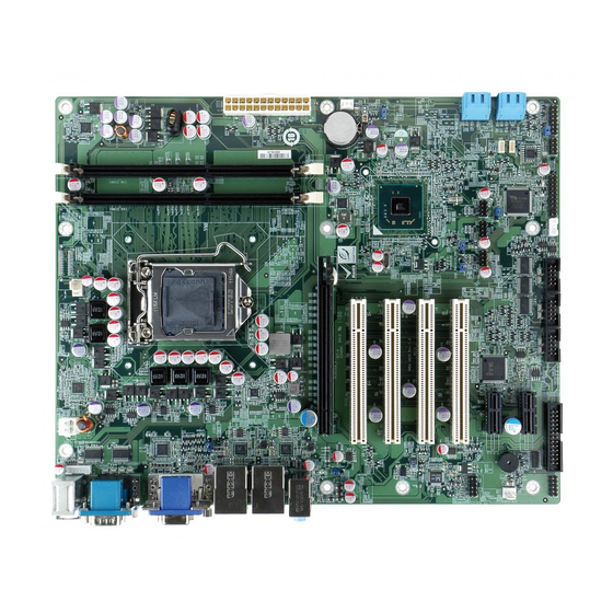
ATX Motherboard supports LGA1155 Intel® Core™ i7/i5/i3,
Pentium®, Celeron® CPU per Intel® H61, DDR3,
VGA/DVI-D, Dual Realtek PCIe GbE, USB 2.0, SATA 3Gb/s,
Quick Installation Guide
Package List
IMBA-H610 package includes the following items:
l
1 x IMBA-H610 Single Board Computer
l
4 x SATA Cable
l
1 x I/O Shielding
l
1 x Mini Jumper Pack
l
1 x Utility CD (within manual)
l
1 x QIG (Quick Installation Guide)
l
1 x One Key Recovery CD
©2011 Copyright by IEI Technology corp.
All manuals and user guides at all-guides.com
HD Audio and RoHS
IMBA-H610
Version 1.01
Aug. 13, 2011
All rights reserved.
1
Advertisement
Table of Contents

Related Manuals for IEI Technology IMBA-H610


Summary of Contents for IEI Technology IMBA-H610
- Page 1 IMBA-H610 Quick Installation Guide Version 1.01 Aug. 13, 2011 Package List IMBA-H610 package includes the following items: 1 x IMBA-H610 Single Board Computer 4 x SATA Cable 1 x I/O Shielding 1 x Mini Jumper Pack 1 x Utility CD (within manual)
-
Page 2: Specifications
All manuals and user guides at all-guides.com Specifications l CPU: LGA1155 socket supports Intel® Core™ i7/i5/i3, Pentium®, Celeron® processor l System chipset: Intel® H61 l BIOS: UEFI BIOS l System memory: Two 240-pin 1333/1066MHz Dual-Channel DDR3 SDRAM Unbuffered DIMM support (system max. 32GB) l Ethernet: Dual Realtek RTL8111E PCIe GbE controllers, LAN1 with ASF2.0 support... -
Page 3: Ordering Information
Humidity: Operation: 5%~95% non-condensing l Dimensions: 244mm x 305mm Ordering Information IMBA-H610-R10: ATX Motherboard supports LGA1155 Intel® Core™ i7/i5/i3, Pentium®, Celeron® CPU per Intel® H61, DDR3, VGA/DVI-D, Dual Realtek PCIe GbE, USB 2.0, SATA 3Gb/s, HD Audio and RoHS 19800-003100-100-RS:Dual ports USB cable with bracket... -
Page 4: Jumpers Setting And Connectors
All manuals and user guides at all-guides.com Jumpers setting and Connectors LABEL FUNCTION J_CMOS1 CMOS State Setting J_AUTO1 AT mode or ATX mode Selection SATA1,2,5,6 Serial ATA 3Gb/s Connector F_PANEL1 Front Panel connector JSPI1 SPI Flash Program Connector TPM1 Trusted Platform Module connector COM3,5,6 Internal Serial Port DB-9 Connectors LPT1... - Page 5 All manuals and user guides at all-guides.com J_COMS1 : Clear CMOS Setup J_AUTO1: ATX mode or AT mode Selection PIN NO. DESCRIPTION PIN NO. DESCRIPTION Short 1-2 Keep CMOS Setup(default) Short 2-3 Clear CMOS Setup OPEN AT Mode SHORT ATX Mode CPU_FAN 1: SYS_FAN1 、...
- Page 6 All manuals and user guides at all-guides.com F_PANEL1 : PWR & RST Buttons and Indicators panel PIN DESCRIPTION PIN DESCRIPTION ACPILED BEEP_PWR PWR_LED BUZZER PWRBTN_SW#_ PC_BEEP PWR_BTN IDELED RESET EXTRST- HDD_LED IDELED- JSPI1: Flash SPI ROM Connector USB01, USB23, USB45 PIN NO.
- Page 7 All manuals and user guides at all-guides.com LPT1 : Parallel Port Connector PIN NO. DESCRIPTION PIN NO. DESCRIPTION STROBE# AUTO FORM FEED # DATA0 ERROR# DATA1 INITIALIZE# DATA2 PRINTER SELECT LN# DATA3 DATA4 DATA5 DATA6 DATA7 ACKNOWLEDG BUSY PAPER EMPTY PRINTER SELECT DIO1 : Digital Input / Output Connector...
- Page 8 All manuals and user guides at all-guides.com I2C_1 COM4 DESCRIPTION DESCRIPTION RXD485# +5V_DUAL RXD485+ PCH_GP38_PU TXD485+ PCH_GP39_PU TXD485# ATX1: 20Pin ATX Power Supply Connector PIN NO. DESCRIPTION PIN NO. DESCRIPTION +3.3Vdc +3.3Vdc +3.3Vdc -12Vdc +5Vdc PS-ON +5Vdc PWR-OK -5Vdc +5VSby +5Vdc +12Vdc +5Vdc...
-
Page 9: Pin Description
All manuals and user guides at all-guides.com KB_MS2 : Mouse & Keyboard Connector DESCRIPTION DESCRIPTION Keyboard Data Mouse Data Keyboard Clock Mouse Clock COM1: External Serial Port Connector DESCRIPTION DATA CARRIER DETECT (DCD1) RECEIVE DATA (RXD1) TRANSMIT DATA (TXD1) DATA TERMINAL READY (DTR1) (GND1) DATA SET READY... - Page 10 All manuals and user guides at all-guides.com Board Layout: Jumper and Connector Locations (Unit:mm)...
Need help?
Do you have a question about the IMBA-H610 and is the answer not in the manual?
Questions and answers