Advertisement
Quick Links
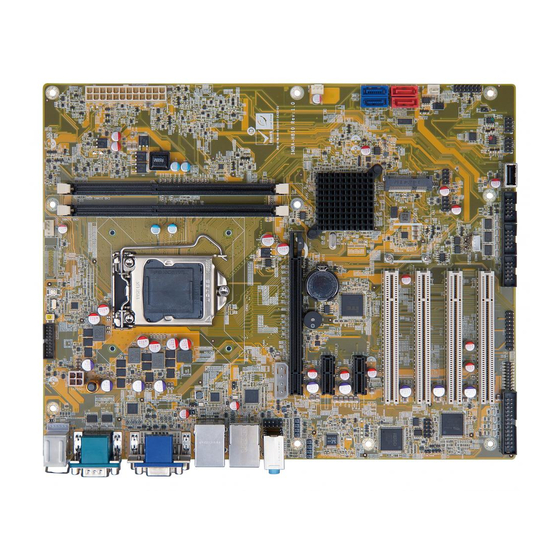
ATX motherboard supports 22nm LGA 1150 4th Generation
Intel® Core™ i7/i5/i3, Pentium® and Celeron® H81, DDR3,
VGA/DVI-D/iDP, Dual Intel® PCIe GbE, USB3.0,
Quick Installation Guide
Package List
IMBA-H810 package includes the following items:
1 x IMBA-H810-R10 Single board computer
1 x I/O shielding
2 x SATA cable
1 x QIG
SATA 6Gb/s, HD Audio and RoHS
IMBA-H810
Version 1.0
March 1, 2023
©2023 Copyright by IEI Integration corp.
All rights reserved.
Advertisement

Subscribe to Our Youtube Channel
Related Manuals for IEI Technology IMBA-H810


Summary of Contents for IEI Technology IMBA-H810
- Page 1 SATA 6Gb/s, HD Audio and RoHS IMBA-H810 Quick Installation Guide Version 1.0 March 1, 2023 Package List IMBA-H810 package includes the following items: 1 x IMBA-H810-R10 Single board computer 1 x I/O shielding 2 x SATA cable ...
-
Page 2: Specifications
Specifications CPU: LGA1150 Intel® Core™ i7/i5/i3, Pentium® and Celeron® processor supported Chipset: Intel® H81 Memory: Two 240-pin 1333/1600 MHz dual-channel DDR3 SDRAM unbuffered DIMM supported (system max. 16GB) BIOS: UEFI BIOS Graphics Engine: Intel® HD Graphics Gen 7.5 supports DX11.1 and OpenCL 1.2, OpenGL 3.2 Full MPEG2, VC1, AVC Decode ... - Page 3 1 x USB 2.0 (180 degree type A) 4 x USB 2.0 (2x4 pin, P=2.54) 2 x SATA 3Gb/s (SATA3, SATA4) (Red) 2 x SATA 6Gb/s (SATA1, SATA2) (H81 supports AHCI, no RAID) (Blue) Audio: Support 5.1 channel HD audio by ALC662 (2x5 pin) ...
-
Page 4: Ordering Information
Dimensions: 244mm x 305mm Ordering Information IMBA-H810: ATX motherboard supports 22nm LGA 1150 4th Gen. Intel® Core™ i7/i5/i3, Pentium® and Celeron® H81, DDR3, VGA/DVI-D/iDP, Dual Intel® PCIe GbE, USB3.0, SATA 6Gb/s, HD Audio and RoHS 19800-000049-RS: LPT cable ... -
Page 5: Jumpers Setting And Connectors
Jumpers setting and connectors LABEL FUNCTION J_ATX_AT1 AT/ATX mode select switch J_CMOS1 Clear CMOS button PCIE x16 Power PCIEX16 Power Setting USB SW1, USB SW2 USB power setting J_FLASH1 Flash Descriptor Security Override MSATA_SW1 MSATA Selection F_PANEL1 PWR & RST Buttons and indicators VIDEO1 VGA 15-pin Female Connector VIDEO1... - Page 6 LED_LAN1 LAN1 LINK LED Connector LED_LAN2 LAN2 LINK LED Connector CHASSIS1 Chassis Status Connector JSPI1 Flash SPI ROM JSPI2 Flash EC ROM EC Debug Port Connector Display Port Connector J_ATX_AT1: AT/ATX mode select switch PIN NO. DESCRIPTION Short 1 - 2 ATX Mode (default) Short 2 - 3 AT Mode...
- Page 7 USB SW1, USB SW2: USB power setting USB SW1 DESCRIPTION +5V DUAL Normal Operation (default) Aptio Setup Utility – Copyright (C) 2012 American Megatrends, Inc. Chipset Auto Power Button Status [Disabled(ATX)] Restore AC Power Loss [Last State] ------------------ > PCI Express Configuration >...
- Page 8 VIDEO1 : 15-pin Female Connector PIN NO. DESCRIPTION PIN NO. DESCRIPTION GREEN BLUE DDCDA HSYNC VSYNC DDCCLK VIDEO1: DVI-I(Dual Link)+CRT PIN NO. DESCRIPTION PIN NO. DESCRIPTION DVI_DATA1 GREEN BLUE Hot Plug Detect DVI_DATA2# HPDET DVI_DATA2 DVI_DATA0# DVI_DATA0 DDC CLK DDC DATA DVI_CLK DVI_DATA1# DVI_CLK#...
- Page 9 LAN1_USB1: Ethernet and USB 3.0 connectors USB1: External USB 3.0 connectors PIN NO. DESCRIPTION PIN NO. DESCRIPTION USB_DATA- USB_DATA- USB_DATA+ USB_ DATA+ USB3_RX- USB3_RX- USB3_RX+ USB3_ RX+ USB3_TX- USB3_TX- USB3_TX+ USB3_TX+ LAN1: RJ-45 LAN connector PIN NO. DESCRIPTION PIN NO. DESCRIPTION LAN1_MDI0P LAN1_MDI2P...
- Page 10 KBMS1: PS/2 Keyboard and mouse connector KBMS1 (Purple): 6-pin Mini-DIN keyboard connector PIN NO. DESCRIPTION PIN NO. DESCRIPTION Keyboard Data Keyboard Clock KBMS1 (Green): 6-pin Mini-DIN Mouse Connector PIN NO. DESCRIPTION PIN NO. DESCRIPTION Mouse Data Mouse Clock KB_MS1: 6-pin header Keyboard/Mouse Connector PIN NO.
- Page 11 COM2: External RS-232 serial port connector PIN NO. DESCRIPTION PIN NO. DESCRIPTION DCD2 RXD2 TXD2 DTR2 GND2 DSR2 RTS2 CTS2 COM3, COM5, COM6: Internal RS-232 serial port connectors Function DESCRIPTION DESCRIPTION COM3 COM5 COM6 AUDIO_CV1 : Audio Line-In/Out MIC Connector PIN NO.
- Page 12 COM4: RS-422/485 serial port connector PIN NO. DESCRIPTION PIN NO. DESCRIPTION RXD485# RXD485+ TXD485+ TXD485# FRONT-PANEL1 : Audio Source Connector PIN NO. DESCRIPTION PIN NO. DESCRIPTION MIC2-L MIC2-R Presence# LINE2-R MIC2-JD FRONT-IO LINE2-JD LINE2-L SATA1, SATA2, SATA3, SATA4: Serial ATA 3.0 connectors PIN NO.
- Page 13 CN2: M-SATA card connector PIN NO. DESCRIPTION PIN NO. DESCRIPTION PCIE_WAKE# +3.3V 1.5V MSATA_CLK# MSATA _CLK PLTRST_N +3.3V PLTRST_N SATA_RX+ +3.3V SATA_RX- 1.5V SMB_CLK SATA_TX- SMB_DATA SATA_TX+ USB_DATA- USB_DATA+ +3.3V +3.3V +3.3V CLINK_CLK CLINK_DATA 1.5V CLINK_RST# MSATA_DET +3.3V CPU_FAN1: CPU fan connector PIN NO.
- Page 14 SYS_FAN1, SYS_FAN2: System fan connector PIN NO. DESCRIPTION PIN NO. DESCRIPTION FANIO +12V (PWM) DIO1 : Digital Input / Output Connector PIN NO. DESCRIPTION PIN NO. DESCRIPTION Output 3 Output 2 Output 1 Output 0 Input 3 Input 2 Input 1 Input 0 ATX1: 24-pin ATX power source connector PIN NO.
- Page 15 ATXPWR1: Additional Power Source Connector PIN NO. DESCRIPTION PIN NO. DESCRIPTION +12V TPM1: Trusted Platform Module Connector PIN NO. DESCRIPTION PIN NO. DESCRIPTION LCLK LFRAME# LRERST# LAD3 LAD2 +3.3V LAD1 LAD0 SB3V SERIRQ GLKRUN# LPCPD# LDRQ# CN1: SMBUS connector PIN NO. DESCRIPTION PIN NO.
- Page 16 LPT1: Parallel Port Connector DESCRIPTION DESCRIPTION STROBE# AUTO FORM FEED # DATA0 ERROR# DATA1 INITIALIZE# DATA2 PRINTER SELECT LN# DATA3 DATA4 DATA5 DATA6 DATA7 ACKNOWLEDGE# BUSY PAPER EMPTY PRINTER SELECT LED_LAN1: LAN Link LED Connector DESCRIPTION DESCRIPTION +3.3V LAN1_LED_LNK#_ACT LED_LAN2: LAN Link LED Connector DESCRIPTION DESCRIPTION +3.3V...
- Page 17 JSPI2: Flash EC ROM connector PIN NO. DESCRIPTION PIN NO. DESCRIPTION +3.3V SPI_CS# SPI_SO SPI_CLK SPI_SI CN3: EC debug connector PIN NO. DESCRIPTION PIN NO. DESCRIPTION EC_EPP_STB# EC_EPP_AFD# EC_EPP_PD0 EC_EPP_PD1 EC_EPP_INIT# EC_EPP_PD2 EC_EPP_SLIN# EC_EPP_PD3 EC_EPP_PD4 EC_EPP_PD5 EC_EPP_BUSY EC_EPP_PD6 EC_EPP_KSI5 EC_EPP_PD7 EC_EPP_KSI4 DP1: DisplayPort connector PIN NO.
- Page 18 Board Layout: Jumper and Connector Locations (Unit: mm)
Need help?
Do you have a question about the IMBA-H810 and is the answer not in the manual?
Questions and answers