Advertisement
Quick Links
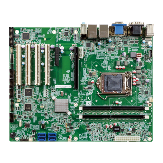
ATX Motherboard Supports 14nm LGA1151 8
Core™ i9/i7/i5/i3, Celeron
Triple Independent Displays, Dual GbE LAN, USB 3.2 Gen 1,
Quick Installation Guide
Package List
IMBA-H310 package includes the following items:
1 x IMBA-H310 single board computer
1 x I/O shielding
2 x SATA cable
1 x QIG
SATA 6Gb/s, HD Audio and RoHS
IMBA-H310
Version 1.0
September 16, 2020
©2020 Copyright by IEI Integration Corp.
All rights reserved.
®
and Pentium
th
th
/9
Generation Intel
®
Processor, DDR4,
®
Advertisement

Related Manuals for IEI Technology IMBA-H310


Summary of Contents for IEI Technology IMBA-H310
- Page 1 SATA 6Gb/s, HD Audio and RoHS IMBA-H310 Quick Installation Guide Version 1.0 September 16, 2020 Package List IMBA-H310 package includes the following items: 1 x IMBA-H310 single board computer 1 x I/O shielding 2 x SATA cable ...
-
Page 2: Specifications
Specifications CPU: ® ™ LGA1151 socket supports 8 generation Intel Core ® ® i9/i7/i5/i3, Celeron and Pentium processor ® System Chipset: Intel H310 Memory: Two 288-pin 2666/2400 MHz dual-channel DDR4 SDRAM un-buffered DIMM slots (system max. 64 GB) ... - Page 3 3 x RS-232 (2x5, p=2.54mm) 1 x RS-232/422/485 (2x5, p=2.54mm) 2 x USB 2.0 (2x4, p=2.54mm) 4 x SATA 6Gb/s (no RAID) Front Audio: 2x5-pin header Front Panel: 1 x Front panel (2x7 pin, power LED, HDD LED, speaker, power button, reset button) ...
-
Page 4: Ordering Information
IEI Resource Download Center IMBA-H310 are available on IEI https://download.ieiworld.com Resource Download Center. Type IMBA-H310 and press Enter to find all the relevant software, utilities, and documentation. To install software from the downloaded ISO file, mount the file as a virtual drive to view its content. - Page 5 Jumpers Settings and Connectors LABEL FUNCTION CPU12V1 +12V power connector ATXPWR1 Additional power connector ATX1 ATX power connector BAT1 Battery connector CHASSIS1 Chassis intrusion connector CHA_DIMM0, DDR4 DIMM sockets CHB_DIMM0 DIO1 Digital I/O connector EC debug connector CPU_FAN1 Fan connector (CPU) SYS_FAN1, SYS_FAN2 Fan connectors (system) FRONT-PANEL1 Front panel audio connector...
- Page 6 LAN2_USB2 connectors External keyboard/mouse and USB 2.0 K/M_USB1 connectors COM1/1 External serial port connector VIDEO1 External VGA and DVI-D connector J_ATX_AT1: AT/ATX Mode Select Switch PIN NO. DESCRIPTION Short 1 - 2 ATX Mode (default) Short 2 - 3 AT Mode J_CMOS1: Clear CMOS Jumper PIN NO.
- Page 7 J_FLASH1: Flash Descriptor Security Override PIN NO. DESCRIPTION Short 1 - 2 Disabled (default) Short 2 - 3 Enabled CPU12V1: +12V Power Connector PIN NO. DESCRIPTION PIN NO. DESCRIPTION +12V +12V ATXPWR1: Additional Power Connector PIN NO. DESCRIPTION PIN NO. DESCRIPTION +12V ATX1: 24-pin ATX Power Connector...
- Page 8 DIO1 : Digital Input / Output Connector PIN NO. DESCRIPTION PIN NO. DESCRIPTION Output 3 Output 2 Output 1 Output 0 Input 3 Input 2 Input 1 Input 0 CN1: EC Debug Connector PIN NO. DESCRIPTION PIN NO. DESCRIPTION EC_EPP_STB# EC_EPP_AFD# EC_EPP_PD0 EC_EPP_PD1...
- Page 9 FRONT-PANEL1 : Front Panel Audio Connector PIN NO. DESCRIPTION PIN NO. DESCRIPTION MIC2-L MIC2-R Presence# LINE2-R MIC2-JD FRONT-IO LINE2-JD LINE2-L F_PANEL1: Front Panel Connector DESCRIPTION DESCRIPTION PWR_LED+ Speaker+ SPKR PWR_LED- PWR_BTN+ Speaker- PWR_BTN- HDD_LED+ Reset+ RESET HDD_LED- Reset- I2C1: I C Connector (to EC) PIN NO.
- Page 10 DP1: Internal DisplayPort Connector PIN NO. DESCRIPTION PIN NO. DESCRIPTION DATA_0P DATA_3N DATA_0N CONFIG1 DATA_1P CONFIG2 AUX_P DATA_1N DATA_2P AUX_N DP_HPD DATA_2N DATA_3P DP_PWR LPT1: Parallel Port Connector PIN NO. DESCRIPTION PIN NO. DESCRIPTION RSTROBE# SIO_AFD# RPD0 SIO_ERR# RPD1 SIO_INIT# RPD2 SIO_SLIN# RPD3...
- Page 11 COM3, COM4, COM6: Internal RS-232 Serial Port Connectors PIN NO. DESCRIPTION PIN NO. DESCRIPTION COM5: Internal RS-232/422/485 Serial Port Connector PIN NO. DESCRIPTION PIN NO. DESCRIPTION S_ATA1, S_ATA2, S_ATA3, S_ATA4: SATA 6Gb/s Connectors PIN NO. DESCRIPTION PIN NO. DESCRIPTION SATA_RX- SATA_TX+ SATA RX+ SATA_TX-...
- Page 12 J_SPI1: SPI Flash Connector (BIOS) PIN NO. DESCRIPTION PIN NO. DESCRIPTION +3.3V SPI_CLK SPI_CS# SPI_SI SPI_SO J_EC1: SPI Flash Connector (EC) PIN NO. DESCRIPTION PIN NO. DESCRIPTION +3.3V_EC SPI_CLK_EC SPI_CS#_EC SPI_SI_EC SPI_SO_EC USB1: Internal USB 2.0 Connector PIN NO. DESCRIPTION PIN NO.
- Page 13 AUDIO_CV1 : Audio Line-In/Out Mic Connector PIN NO. DESCRIPTION Line_In CD/DVD or other audio source input port (Blue) Line_Out Connect this port to headphone or speaker (Green) Microphone Connect this port to microphone (Pink) LAN1_USB1, LAN2_USB2: Ethernet and USB 3.2 Gen 1 Connectors USB1, USB2: External USB 3.2 Gen 1 Connectors PIN NO.
- Page 14 VIDEO1: VGA Connector and DVI-D Connector VGA Connector PIN NO. DESCRIPTION PIN NO. DESCRIPTION GREEN BLUE DDCDA HSYNC VSYNC DDCCLK DVI-D Connector PIN NO. DESCRIPTION PIN NO. DESCRIPTION DATA2- DATA2+ VCC +5V SHIELD24 DATA0- DDCCLK DATA0+ DDCDATA SHIELD05 DATA- DATA1+ SHIELDCLK SHIELD13 CLK2+...
- Page 15 K /M_USB1: PS/2 Keyboard & Mouse and USB 2.0 Port Connectors USB1: External USB 2.0 Connector PIN NO. DESCRIPTION PIN NO. DESCRIPTION USB_DATA- USB_DATA- USB_DATA+ USB_DATA+ KB_MS1: PS/2 Keyboard and Mouse Connector PIN NO. DESCRIPTION PIN NO. DESCRIPTION KEYBOARD DATA MOUSE DATA KEYBOARD CLOCK MOUSE CLOCK...
- Page 16 Board Layout: Jumper and Connector Locations (Unit: mm)
Need help?
Do you have a question about the IMBA-H310 and is the answer not in the manual?
Questions and answers