Sign In
Upload
Manuals
Brands
Delta Electronics Manuals
Servo Drives
ASDA-B2 series
Delta Electronics ASDA-B2 series Manuals
Manuals and User Guides for Delta Electronics ASDA-B2 series. We have
1
Delta Electronics ASDA-B2 series manual available for free PDF download: User Manual
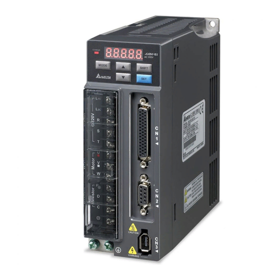
Delta Electronics ASDA-B2 series User Manual (335 pages)
Delta standart AC Servo Drive of general-purpose applications
Brand:
Delta Electronics
| Category:
Servo Drives
| Size: 6.16 MB
Table of Contents
Table of Contents
6
Chapter 1 Unpacking Check and Model Explanation
15
Model Explanation
15
Nameplate Information
15
Model Name Explanation
17
Servo Drive and Servo Motor Combinations
19
Servo Drive Features
20
Control Modes of Servo Drive
21
Chapter 2 Installation and Storage
22
Installation Notes
22
Storage Conditions
22
Installation Conditions
23
Installation Procedure and Minimum Clearances
24
Circuit Interrupter and Fuse Current Recommended Value
26
EMI Filter Selection
27
Regenerative Resistor
29
Chapter 3 Connections and Wiring
36
Connections
36
Connecting to Peripheral Devices
36
Servo Drive Connectors and Terminals
37
Wiring Methods
40
Motor Power Cable Connector Specifications
42
Encoder Connector Specifications
44
Cable Specifications for Servo Drive
48
Basic Wiring
50
And below Models
50
Model
51
1Kw~1.5Kw Models
52
2Kw~3Kw Models
53
Input / Output Interface Connector - CN1
54
CN1 Terminal Identification
55
Signals Explanation of Connector CN1
56
Wiring Diagrams of I/O Signals - CN1
64
Encoder Connector CN2
72
Serial Communication Connector CN3
75
Analog Monitor Output Connector - CN5
76
Standard Connection Example
77
Position (PT) Control Mode
77
Speed Control Mode
78
Torque Control Mode
79
Chapter 4 Display and Operation
80
Description of Digital Keypad
80
Display Flowchart
81
Status Display
83
Save Setting Display
83
Fault Message Display
83
Polarity Setting Display
83
Monitor Setting Display
84
General Function Operation
87
Fault Code Display Operation
87
JOG Operation
88
Force Output Control Operation
89
DI Diagnosis Operation
91
DO Diagnosis Operation
92
Chapter 5 Trial Run and Tuning Procedure
94
Inspection Without Load
94
Applying Power to the Drive
96
JOG Trial Run Without Load
100
Speed Trial Run Without Load
102
Tuning Procedure
104
Tuning Flowchart
105
Load Inertia Estimation Flowchart
106
Auto Mode Tuning Flowchart
107
Semi-Auto Mode Tuning Flowchart
108
Limit of Load Inertia Estimation
110
Mechanical Resonance Suppression Method
112
Relationship between Tuning Modes and Parameters
113
Gain Adjustment in Manual Mode
114
Chapter 6 Control Modes of Operation
116
Control Modes of Operation
117
Position Control Mode
117
Command Source of Position (PT) Control Mode
117
Structure of Position Control Mode
121
Electronic Gear Ratio
122
Low-Pass Filter
124
Position Loop Gain Adjustment
125
Speed Control Mode
127
Command Source of Speed Control Mode
127
Structure of Speed Control Mode
129
Smoothing Strategy of Speed Control Mode
130
Analog Speed Input Scaling
134
Timing Chart of Speed Control Mode
135
Speed Loop Gain Adjustment
135
Resonance Suppression
142
Torque Control Mode
150
Command Source of Torque Control Mode
150
Structure of Torque Control Mode
151
Smoothing Strategy of Torque Control Mode
152
Analog Torque Input Scaling
153
Timing Chart of Torque Control Mode
154
Control Mode Selection
155
Speed / Position Control Mode Selection
155
Speed / Torque Control Mode Selection
156
Torque / Position Control Mode Selection
156
Others
157
Speed Limit
157
Torque Limit
157
Analog Monitor
158
Electromagnetic Brake
162
Chapter 7 Parameters
166
Definition
166
Parameter Summary
167
Detailed Parameter Listings
175
Group 0: P0-XX Monitor Parameters
175
Group 1: P1-XX Basic Parameters
186
Group 2: P2-XX Extension Parameters
214
Group 3: P3-XX Communication Parameters
243
Group 4: P4-XX Diagnosis Parameters
248
Table 7.1 Input Function Definition (DI)
258
Table 7.2 Output Function Definition (DO)
264
Chapter 8 MODBUS Communications
268
Communication Hardware Interface
268
Communication Parameter Settings
271
MODBUS Communication Protocol
274
Communication Parameter Write-In and Read-Out
283
Chapter 9 Troubleshooting
286
Fault Messages Table
286
Potential Cause and Corrective Actions
288
Clearing Faults
297
Chapter 10 Specifications
300
Specifications of Servo Drives (ASDA-B2 Series)
300
Specifications of Servo Motors (ECMA Series)
303
Servo Motor Speed-Torque Curves
307
Overload Characteristics
308
Dimensions of Servo Drives
310
Dimensions of Servo Motors
314
Appendix A Accessories
318
Appendix B Maintenance and Inspection
332
Advertisement
Advertisement
Related Products
Delta Electronics ASDA-AB Series
Delta Electronics ASD-A3023-AB
Delta Electronics ASD-A0121L
Delta Electronics ASD-A0221L
Delta Electronics ASD-A0421L
Delta Electronics ASD-A1021L
Delta Electronics ASD-A2023L
Delta Electronics ASD-A3023L
Delta Electronics ASD-A1521M
Delta Electronics ASD-A2023M
Delta Electronics Categories
Power Inductor
Power Supply
Computer Hardware
Fan
Transceiver
More Delta Electronics Manuals
Login
Sign In
OR
Sign in with Facebook
Sign in with Google
Upload manual
Upload from disk
Upload from URL