Sign In
Upload
Manuals
Brands
APRILIA Manuals
Motorcycle
TUAREG 660
APRILIA TUAREG 660 Manuals
Manuals and User Guides for APRILIA TUAREG 660. We have
2
APRILIA TUAREG 660 manuals available for free PDF download: Service Station Manual, Instruction Manual
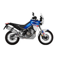
APRILIA TUAREG 660 Service Station Manual (312 pages)
Brand:
APRILIA
| Category:
Motorcycle
| Size: 15.96 MB
Table of Contents
The Value of Service
2
Index of Topics
5
Unpacking Procedure of the Vehicle
7
Assembly
10
Handguard Installation Procedure
10
Rear-View Mirror Installation
11
Windscreen Installation
12
Aesthetic Inspection
12
Tightening Torques Inspection
13
Electrical System Check
13
Battery Check
14
Charge Level
14
Recharge
14
Charge Modes
14
Traditional Battery Activation Procedure
15
Levels Check
16
Road Test
16
Static Test
16
Functional Inspection
17
Characteristics
18
Safety Rules
19
Carbon Monoxide
19
Safe Handling of Fuel
19
Safe Handling of Coolant
19
Maintenance Rules
20
Used Engine Oil and Transmission Oil
20
Battery Electrolyte and Hydrogen Gas
20
Reassembling the Components
21
Electrical Connectors
21
Running-In
22
Vehicle Identification
23
Serial Number Location
23
Frame Number
23
Dimensions and Mass
24
Engine Specifications
24
Transmission Data
24
Engine Number
24
Capacities
25
Drive Chain Data
25
Electrical System Data
25
Frame and Suspensions Data
26
Brakes Data
26
Wheels and Tyres Data
27
Supply
27
Tightening Torques
27
Special Tools
29
Maintenance
35
Scheduled Maintenance Table
36
Recommended Products
37
Spark Plug
37
Engine Oil Check
38
Engine Oil Replacement
39
Engine Oil Filter
41
Air Filter
41
Throttle Body Removal
42
Throttle Body Installation
46
Air Filter Housing
46
Air Filter Housing Removal
47
Calibrated Pad Thickness
49
Cooling System Maintenance
51
Coolant Level Check
51
Collant Top-Up
51
Braking System Maintenance
51
Checking Brake Fluid
52
Brake Fluid Top-Up
52
Front Braking System
53
Rear Braking System
53
Adjusting the Levers
54
Front Brake Lever Adjustment
54
Rear Brake Lever Adjustment
54
Clutch Lever Adjustment
54
Regolazione Leva Frizione
54
Headlight Adjustment
55
Vertical Adjustment of the Light Beam
56
High Beam Headlight
56
Index of Topics
57
Electrical System
57
Electrical System Installation
58
USB Pre-Assembly
60
Front Side
60
Outside Air Temperature Sensor Pre-Assembly
61
Pre-Assembly of Edge Fixing Ties on the Instrument Cluster Support
61
Pre-Assembly of the Front Instrument Cluster Support
62
Headlight Pre-Assembly
62
Ignition Block Pre-Assembly
63
Right Switch Cluster Pre-Assembly
63
Left Switch Cluster Pre-Assembly
64
Clutch Switch Pre-Assembly
65
Front ABS Sensor Pre-Assembly
65
Front ABS Sensor
66
Handlebar and Ignition Block Area Cable Routing
67
Routing the Cables in the Instrument Panel Support Area
69
Instrument Panel Area Connectors Connection Sequence
71
Rear Brake Switch Pre-Assembly
75
Side-Stand Sensor Pre-Assembly
75
Radiator Fan Pre-Assembly
76
Pre-Assembly of the Cable Guides for the Passage of Starter Cables
77
Pre-Assembly of the Cable Guide on the Tank
78
Pre-Assembly of the Fuel Level Probe on the Tank
78
Engine ECU Bracket Pre-Assembly
79
Gear Sensor Cable Passage
79
Ground and ABS Cable on Engine
81
Connection of Throttle Valve, Secondary Air Valve
81
Engine Head Area Connections
82
Correct Fitting of the ABS Control Unit Connector
83
Oil Temperature Sensor and Oil Pressure Sensor
84
Horn Connection
86
Main Wiring Harness
86
Fall Sensor
87
Ecu
88
Starter Motor and Ground Lead
89
Left Lambda Probe
89
Right Lambda Probe
90
Left Electric Fan
91
Right Electric Fan
92
Voltage Regulator
93
Filter Box Air Temperature Sensor
93
Fuel Level Probe
94
Under Seat Compartment Pre-Assembly
96
Pre-Assembly of the Turn Indicators on License Plate Holder
96
Back Side
96
Tail-Light Pre-Assembly
97
Starter Relay Area Cable Passage on Left Side of Seat Post
97
Side Stand Cable Route
99
Tail-Lights and Turn Indicators
100
Relay Area Cable Routing on Right Side
102
Fuse Boxes
104
Rear ABS Sensor
105
OBDII Connector
107
General Wiring Diagram
108
Storing New Keys
110
Battery Recharge Circuit
112
Battery Voltage
112
Recharge System Connections
113
Continuity of the Three Phases of the Stator
113
Isolation of the Generator Phases
114
Consumption Check with the Switch to off
114
Error Related to the Battery Voltage
116
Preliminary Check of the Recharge System
116
Fuses Check
118
Auxiliary Fuses Distribution
119
Control Unit
120
Location of the Main Fuse
120
Engine Tone Wheel Programming Procedure
120
Index of Topics
122
Engine from Vehicle
122
Power Supply
126
Power Supply
127
Fuel Pump Removal
127
Suspensions
130
Front Suspension
130
Handlebar Removal
130
Front Fork Adjustment
132
Removing the Fork Legs
134
Draining Oil
135
Disassembling the Fork
137
Checking the Components
138
Reassembling the Fork
139
Filling Oil (Front Fork)
140
Upper Steering Yoke Removal
143
Upper Steering Yoke
145
Installation
145
Steering Bottom Yoke Removal
146
Steering Bottom Yoke Installation
147
Steering Bearing - Adjusting Play
149
Steering Bearing Disassembly
150
Steering Bearing Assembly
153
Rear Suspension
156
Shock Absorbers Adjustment
156
Standard Adjustment
158
Shock Absorbers Removal
159
Linkages Removal
160
Linkages Check
161
Linkages Installation
162
Index of Topics
164
Chassis
165
Front Wheel Removal
165
Removal of Internal Wheel Components
166
Removal of External Wheel Components
168
Front Wheel Check
168
Front Wheel Bearings
168
Front Wheel Axle Check
169
Front Wheel Installation
170
Front Wheel Internal Components Installation
171
Check the Free Rotation of both Bearings
172
Rear Wheel Removal
173
Removal of External Wheel Components (Rear)
175
Removal of Internal Wheel Components (Rear)
177
Rear Sprocket Support Disassembly
178
Rear Wheel Check
180
Rear Wheel Gaskets
180
Checking Rotation
180
Rear Wheel Installation
181
Rear Wheel Axle Check
181
Rear Wheel Rim Check
181
Installation of Internal Wheel Components (Rear)
184
Installation of External Wheel Components (Rear)
185
Swinging Arm Removal
189
Swinging Arm Check
191
Swinging Arm Installation
192
Left Side
192
Right Side
192
Pinion Removal
194
Pinion Inspection
197
Pinion Installation
197
Drive Chain Removal
199
Drive Chain Inspection
201
Drive Chain Installation
201
Drive Chain Adjustment
203
Chain Sliders
204
Chain Guard
204
Chain Guide
205
Chain Roller
205
Left Rider Footrest Disassembly and Removal
206
Right Rider Footrest
208
Passenger Footrests
210
Left Rider Footrest Installation
212
Installazione
212
Side Stand Removal
219
Index of Topics
221
Braking System
222
ABS System Description
222
ABS Functional Diagram
225
Operating Diagram
225
ABS Operation
226
ABS Cycle Phases
226
ABS Modulator Replacement
228
ABS Control Unit Connector Insertion
231
Rear Brake Calliper Removal
232
Rear Brake Calliper Installation
235
Front Brake Caliper Removal
239
Front Brake Caliper Installation
242
Rear Brake Disc Removal
244
Rear Brake Disc Inspection
245
Rear Brake Disc Installation
246
Front Brake Disc Removal
246
Front Brake Disc Inspection
247
Front Brake Disc Installation
248
Front Brake Pads Removal
248
Front Brake Pads Installation
249
Rear Brake Pads Removal
250
Rear Brake Pads Installation
251
Bleeding the Braking System
252
Front Brake Pump Removal
255
Front Brake Pump Installation
256
Rear Brake Pump Removal
256
Brake System Lines Removal
258
Index of Topics
264
Cooling System
265
Water Pump Removal
265
Water Pump Installation
266
Removing the Radiator
269
Removing the Expansion Tank
271
Thermostatic Valve Removal
272
Thermostatic Valve Installation
273
Bodywork
275
Seat Removal
275
Hand Guards Removal
275
To Remove the Light Switches
277
Left Switch Cluster Removal
279
Removing the Rear-View Mirrors
281
To Remove the Instrument Panel
282
Headlight Assy
282
To Remove the Front Light Cluster
282
Turn Indicators
284
Disassembling the Lock
285
Taillight Assy
287
License Plate Light
288
Side Body Panels Disassembly
289
Side Fairings Removal
289
License Plate Holder Removal
291
Splash Guard Removal
291
Sump Guard Removal
292
Fuel Tank Removal and Disassembly
293
Rear Wheelhouse
299
Front Mudguard Removal
300
Instrument Cluster Cover Removal
301
Windscreen Removal
302
Instrument Cluster Support
303
Central Instrument Panel Support
305
Radiator Cover Removal
306
To Remove the Battery
306
Tail Guard
307
Side Air Deflectors
309
Index
310
Advertisement
APRILIA TUAREG 660 Instruction Manual (194 pages)
Brand:
APRILIA
| Category:
Motorcycle
| Size: 2.49 MB
Table of Contents
Table of Contents
5
General Rules
7
Foreword
8
Motorcycle Care
8
Carbon Monoxide
11
Fuel
12
Hot Components
12
Coolant
13
Used Engine Oil and Gearbox Oil
13
Brake Fluid
14
Battery Hydrogen Gas and Electrolyte
14
Stand
15
Precautions General Advice
16
Vehicle
19
Arrangement of the Main Components
20
Dashboard
23
Digital Instrument Panel
24
Light Unit
26
Digital Lcd Display
26
Alarms
33
Mapping Selection
37
Control Buttons
40
Advanced Functions
54
Ignition Switch
74
Locking the Steering Wheel
76
Horn Button
76
Switch Direction Indicators
77
High/Low Beam Selector
78
Passing Button
78
Daytime/Night Lights Switch
79
Heated Handgrip Control
80
Start-Up Button
81
Engine Stop Switch
81
Button Cruise Control
82
System A-PRC (Aprilia Performance Ride Control) (02_107
84
Immobilizer System Operation
96
Opening the Saddle
98
USB Port
99
Identification
100
Use
103
Checks
104
Refuelling
107
Rear Shock Absorbers Adjustment
110
Rear Shock Absorbers Setting
112
Front Fork Adjustment
114
Front Fork Setting
115
Justering Af Greb Til Forbremse
117
Clutch Lever Adjustment
118
Running in
118
Starting up the Engine
119
Moving off / Riding
122
Stopping the Engine
126
Parking
127
Catalytic Silencer
128
Stand
129
Suggestion to Prevent Theft
129
Safe Driving
130
Basic Safety Rules
132
Maintenance
137
Foreword
138
Engine Oil Level Check
138
Engine Oil Top-Up
140
Engine Oil Change
140
Engine Oil Filter Replacement
140
Tyres
141
Spark Plug Dismantlement
142
Removing the Air Filter
142
Cooling Fluid Level
143
Coolant Check
144
Coolant Top-Up
144
Checking the Brake Oil Level
144
Braking System Fluid Top up
145
Battery
148
Battery Removal
149
Use of a New Battery
150
Charging the Battery
152
Long Periods of Inactivity
153
Fuses
154
Lamps
159
Front Light Group
160
Headlight Adjustment
160
Front Direction Indicators
162
Rear Optical Unit
162
Rear Turn Indicators
162
Number Plate Light
162
Rear-View Mirrors
163
Front and Rear Disc Brake
164
Periods of Inactivity
165
Cleaning the Vehicle
166
Transport
170
Transmission Chain
171
Chain Backlash Check
172
Chain Backlash Adjustment
173
Checking Wear of Chain, Front and Rear Sprockets
173
Chain Lubrication and Cleaning
174
Technical Data
175
Data
176
Programmed Maintenance
187
Scheduled Maintenance Table
188
Recommended Products
191
Advertisement
Related Products
APRILIA TUONO - BROCHURE 2009
APRILIA TUONO R
APRILIA Tuono V4 1100 Factory 2021
APRILIA TUONO R FACTORY 2009
APRILIA TUONO R FACTORY 2010
APRILIA TUONO R FACTORY 2008
APRILIA TUONO R FACTORY 2007
APRILIA Tuono 125 Euro 4
APRILIA TUONO V4 R 2013
APRILIA TUONO V4 R 2012
APRILIA Categories
Motorcycle
Scooter
Bicycle
Engine
Hair Dryer
More APRILIA Manuals
Login
Sign In
OR
Sign in with Facebook
Sign in with Google
Upload manual
Upload from disk
Upload from URL