ZyXEL Communications UAG5100 User Manual
Unified access gateway
Hide thumbs
Also See for UAG5100:
- User manual (505 pages) ,
- Firmware release notes (29 pages) ,
- Quick start manual (2 pages)
Table of Contents
Advertisement
Quick Links
UAG Series
UAG2100 / UAG4100 / UAG5100
Unified Access Gateway
Version 4.10
Edition 1, 03/2015
Quick Start Guide
User's Guide
Default Login Details
LAN IP Address
http://172.16.0.1 (LAN1)
http://172.17.0.1 (LAN2)
User Name
www.zyxel.com
Password
admin
1234
Copyright © 2015 ZyXEL Communications Corporation
Advertisement
Table of Contents
Troubleshooting

Related Manuals for ZyXEL Communications UAG5100


Summary of Contents for ZyXEL Communications UAG5100
- Page 1 UAG Series UAG2100 / UAG4100 / UAG5100 Unified Access Gateway Version 4.10 Edition 1, 03/2015 Quick Start Guide User’s Guide Default Login Details LAN IP Address http://172.16.0.1 (LAN1) http://172.17.0.1 (LAN2) User Name www.zyxel.com admin Password 1234 Copyright © 2015 ZyXEL Communications Corporation...
- Page 2 IMPORTANT! READ CAREFULLY BEFORE USE. KEEP THIS GUIDE FOR FUTURE REFERENCE. Screenshots and graphics in this book may differ slightly from your product due to differences in your product firmware or your computer operating system. Every effort has been made to ensure that the information in this manual is accurate.
-
Page 3: Table Of Contents
Contents Overview Contents Overview Introduction .............................20 Hardware Installation and Connection ....................36 Printer Deployment ..........................42 Installation Setup Wizard ........................50 Quick Setup Wizards ..........................64 Dashboard ...............................80 Monitor ..............................91 Licensing ...............................131 Wireless ..............................136 Interfaces ..............................154 Trunks ..............................195 Policy and Static Routes ........................203 DDNS ..............................214 NAT ...............................219 VPN 1-1 Mapping ..........................226 HTTP Redirect ............................231... - Page 4 Contents Overview Services ..............................447 Schedules .............................453 AAA Server ............................459 Authentication Method ..........................464 Certificates ............................467 ISP Accounts ............................483 System ..............................486 Log and Report .............................534 File Manager ............................549 Diagnostics ............................560 Packet Flow Explore ..........................572 Reboot ..............................581 Shutdown ..............................582 Troubleshooting ............................583 UAG Series User’s Guide...
-
Page 5: Table Of Contents
1.4.4 Tables and Lists ........................32 1.5 Stopping the UAG ..........................35 Chapter 2 Hardware Installation and Connection .....................36 2.1 Rack-mounting (UAG5100) .......................36 2.2 Wall Mounting (UAG2100 and UAG4100) ..................37 2.3 Front Panel ............................38 2.3.1 Front Panel LEDs ........................39 2.4 Rear Panel ............................40 2.4.1 UAG2100 or UAG4100 ......................40... - Page 6 Table of Contents 4.2.2 Internet Settings: PPPoE ......................53 4.2.3 Internet Settings: PPTP ......................54 4.2.4 Internet Settings - Second WAN Interface ................55 4.3 Wireless Settings ..........................56 4.3.1 Wireless and Radio Settings ....................56 4.4 Web Authentication Settings ......................57 4.5 Printer Settings ..........................58 4.5.1 Printer List and Printout Settings .....................59 4.6 Billing Settings ..........................59 4.6.1 Billing Profile ...........................60...
- Page 7 Table of Contents 6.2.3 The Active Sessions Screen ....................87 6.2.4 The VPN Status Screen ......................88 6.2.5 The DHCP Table Screen ......................88 6.2.6 The Number of Login Users Screen ..................89 Chapter 7 Monitor..............................91 7.1 Overview ............................91 7.1.1 What You Can Do in this Chapter ....................91 7.2 The Port Statistics Screen .......................92 7.2.1 The Port Statistics Graph Screen ...................93 7.3 The Interface Status Screen ......................94...
- Page 8 Table of Contents 8.2 Registration Screen .........................132 8.3 Service Screen ..........................132 8.4 App Patrol Signature Update Screen .....................133 Chapter 9 Wireless .............................136 9.1 Overview ............................136 9.1.1 What You Can Do in this Chapter ..................136 9.1.2 What You Need to Know ......................136 9.2 Controller Screen ...........................137 9.3 AP Management Screen ........................137 9.3.1 Edit AP List ...........................139...
- Page 9 Table of Contents 10.6.2 Bridge Interface Add/Edit ....................184 10.7 Virtual Interfaces ...........................189 10.7.1 Virtual Interfaces Add/Edit ....................190 10.8 Interface Technical Reference .......................191 Chapter 11 Trunks ..............................195 11.1 Overview ............................195 11.1.1 What You Can Do in this Chapter ..................195 11.1.2 What You Need to Know ......................195 11.2 The Trunk Summary Screen ......................198 11.2.1 Configuring a User-Defined Trunk ..................199 11.2.2 Configuring the System Default Trunk ................201...
- Page 10 Table of Contents 15.1 VPN 1-1 Mapping Overview ......................226 15.1.1 What You Can Do in this Chapter ..................226 15.1.2 What You Need to Know ......................226 15.2 The VPN 1-1 Mapping General Screen ..................227 15.2.1 The VPN 1-1 Mapping Edit Screen ..................228 15.3 The VPN 1-1 Mapping Profile Screen ...................229 Chapter 16 HTTP Redirect ...........................231...
- Page 11 Table of Contents 20.1 IP/MAC Binding Overview ......................248 20.1.1 What You Can Do in this Chapter ..................248 20.1.2 What You Need to Know ......................248 20.2 IP/MAC Binding Summary ......................249 20.2.1 IP/MAC Binding Edit ......................250 20.2.2 Static DHCP Edit .........................251 20.3 IP/MAC Binding Exempt List ......................251 Chapter 21 Layer 2 Isolation ..........................253 21.1 Overview ............................253...
- Page 12 Table of Contents 24.1.1 What You Can Do in this Chapter ..................286 24.2 Before You Begin ..........................287 24.3 Configuring RTLS ..........................287 Chapter 25 Security Policy ..........................289 25.1 Overview ............................289 25.1.1 What You Can Do in this Chapter ..................289 25.1.2 What You Need to Know ......................290 25.2 Security Policy Control Screen ......................291 25.2.1 Configuring the Security Policy Control Screen ..............292 25.2.2 Add/Edit Policy Control Rule ....................294...
- Page 13 Table of Contents 27.4.4 Daily Account Summary ......................328 27.4.5 Monthly Account Summary ....................329 27.4.6 Account Report Notes ......................330 27.4.7 System Status ........................330 Chapter 28 Free Time ............................332 28.1 Overview ............................332 28.1.1 What You Can Do in this Chapter ..................332 28.2 The Free Time Screen ........................332 Chapter 29 SMS ..............................336 29.1 Overview ............................336...
- Page 14 Table of Contents 32.2.1 Add/Edit Application Patrol Profile ..................378 32.2.2 Add/Edit Application Patrol Profile Rule Application ............380 Chapter 33 Content Filtering ..........................381 33.1 Overview ............................381 33.1.1 What You Can Do in this Chapter ..................381 33.1.2 What You Need to Know ......................381 33.1.3 Before You Begin .........................382 33.2 Content Filter Profile Screen ......................383 33.2.1 Add/Edit Content Filter Profile .....................385...
- Page 15 Table of Contents 36.1.2 What You Need To Know .....................414 36.2 Radio Screen ..........................415 36.2.1 Add/Edit Radio Profile ......................417 36.3 SSID Screen ..........................420 36.3.1 SSID List ..........................420 36.3.2 Add/Edit SSID Profile ......................422 36.3.3 Security List .........................424 36.3.4 Add/Edit Security Profile ......................425 36.3.5 MAC Filter List ........................428 36.3.6 Add/Edit MAC Filter Profile ....................428 Chapter 37...
- Page 16 Table of Contents 40.1.2 What You Need to Know ......................447 40.2 The Service Summary Screen ......................448 40.2.1 The Service Add/Edit Screen ....................449 40.3 The Service Group Summary Screen ..................450 40.3.1 The Service Group Add/Edit Screen ...................451 Chapter 41 Schedules............................453 41.1 Overview ............................453 41.1.1 What You Can Do in this Chapter ..................453 41.1.2 What You Need to Know ......................453 41.2 The Schedule Summary Screen ....................454...
- Page 17 Table of Contents 44.2.3 The My Certificates Import Screen ..................476 44.3 The Trusted Certificates Screen ....................477 44.3.1 The Trusted Certificates Edit Screen ..................479 44.3.2 The Trusted Certificates Import Screen ................481 Chapter 45 ISP Accounts.............................483 45.1 Overview ............................483 45.1.1 What You Can Do in this Chapter ..................483 45.2 ISP Account Summary ........................483 45.2.1 ISP Account Edit .........................484 Chapter 46...
- Page 18 Table of Contents 46.8 SSH ............................518 46.8.1 How SSH Works ........................519 46.8.2 SSH Implementation on the UAG ..................520 46.8.3 Requirements for Using SSH ....................520 46.8.4 Configuring SSH ........................520 46.8.5 Secure Telnet Using SSH Examples ...................521 46.9 Telnet ............................523 46.9.1 Configuring Telnet ........................523 46.10 FTP ............................524 46.10.1 Configuring FTP ........................524 46.11 SNMP ............................525...
- Page 19 Table of Contents 49.1 Overview ............................560 49.1.1 What You Can Do in this Chapter ..................560 49.2 The Diagnostics Screen ........................560 49.2.1 The Diagnostics Files Screen ....................561 49.3 The Packet Capture Screen ......................562 49.3.1 The Packet Capture Files Screen ..................565 49.4 The Core Dump Screen ........................566 49.4.1 The Core Dump Files Screen ....................566 49.5 The System Log Screen ........................567 49.6 The Network Tool Screen ......................568...
-
Page 20: Introduction
H A PT ER Introduction 1.1 Overview This User’s Guide covers the following models: UAG2100, UAG4100 and UAG5100. Table 1 UAG Series Comparison Table FEATURES UAG2100 UAG4100 UAG5100 SMS Service Subscription IPSec VPN (Site-to-Site) Content Filtering Application Patrol Local AP (Built-in Wireless LAN Module) Drop-in Mode The UAG is a comprehensive service gateway. -
Page 21: Default Zones, Interfaces, And Ports
Figure 1 Zones, Interfaces, and Physical Ethernet Ports UAG2100 / UAG4100 LAN1 LAN2 Zones Interfaces wan1 lan1 lan2 Physical Ports UAG5100 Zones LAN1 LAN2 Interfaces wan1 wan2 lan1 lan2 Physical Ports 1.3 Management Overview You can manage the UAG in the following ways. -
Page 22: Web Configurator
Chapter 1 Introduction Figure 2 Managing the UAG: Web Configurator Command-Line Interface (CLI) The CLI allows you to use text-based commands to configure the UAG. Access it using remote management (for example, SSH or Telnet) or via the physical or Web Configurator console port. See the Command Reference Guide for CLI details. -
Page 23: Web Configurator Access
UAG is using its default configuration; otherwise the dashboard appears. 1.4.2 Web Configurator Screens Overview This guide uses the UAG5100 screens as an example. The screens may vary slightly for different models. The Web Configurator screen is divided into these parts (as illustrated on... -
Page 24: Title Bar
Chapter 1 Introduction • B - navigation panel • C - main window 1.4.2.1 Title Bar Figure 3 Title Bar The title bar icons in the upper right corner provide the following functions. Table 3 Title Bar: Web Configurator Icons LABEL DESCRIPTION Logout... - Page 25 Chapter 1 Introduction Site Map Click Site MAP to see an overview of links to the Web Configurator screens. Click a screen’s link to go to that screen. Figure 5 Site Map Object Reference Click Object Reference to open the Object Reference screen. Select the type of object and the individual object and click Refresh to show which configuration settings reference the object.
-
Page 26: Navigation Panel
Chapter 1 Introduction The fields vary with the type of object. The following table describes labels that can appear in this screen. Table 5 Object References LABEL DESCRIPTION Object Name This identifies the object for which the configuration settings that use it are displayed. Click the object’s name to display the object’s configuration screen in the main window. -
Page 27: Monitor Menu
Chapter 1 Introduction Figure 8 Navigation Panel Dashboard The dashboard displays general device information, system status, system resource usage, licensed service status, and interface status in widgets that you can re-arrange to suit your needs. See Chapter 6 on page 80 for details on the dashboard. -
Page 28: Configuration Menu
Chapter 1 Introduction Table 6 Monitor Menu Screens Summary (continued) FOLDER OR LINK TAB FUNCTION Station Info Display information about the connected stations. Detected Display information about suspected rogue APs. Device Printer Status Printer Status Display information about the connected statement printers. VPN 1-1 Mapping VPN 1-1 Display the status of the active users to which the UAG applied a VPN 1-1... - Page 29 Chapter 1 Introduction Table 7 Configuration Menu Screens Summary (continued) FOLDER OR LINK TAB FUNCTION Auto Healing Enable auto healing to extend the wireless service coverage area of the managed APs when one of the APs fails. Network Interface Port Role Use this screen to set the UAG’s flexible ports as LAN1 or LAN2.
- Page 30 Chapter 1 Introduction Table 7 Configuration Menu Screens Summary (continued) FOLDER OR LINK TAB FUNCTION Printer General Setting Configure the printer list, enable printer management and customize the account printout. Printer Manager Detect the connected statement printers, change their IP addresses and/or add them to the managed printer list.
- Page 31 Chapter 1 Introduction Table 7 Configuration Menu Screens Summary (continued) FOLDER OR LINK TAB FUNCTION AAA Server RADIUS Configure the RADIUS settings. Auth. Method Authentication Create and manage ways of authenticating users. Method Certificate My Certificates Create and manage the UAG’s certificates. Trusted Certificates Import and manage certificates from trusted sources.
-
Page 32: Tables And Lists
Chapter 1 Introduction Table 8 Maintenance Menu Screens Summary (continued) FOLDER OR FUNCTION LINK Diagnostics Diagnostic Collect diagnostic information. Packet Capture Capture packets for analysis. Core Dump Connect a USB device to the UAG and save a process’s core dump to the attached USB storage device if the process terminates abnormally (crashes). - Page 33 Chapter 1 Introduction Figure 10 Common Table Column Options Select a column heading cell’s right border and drag to re-size the column. Figure 11 Resizing a Table Column Select a column heading and drag and drop it to change the column order. A green check mark displays next to the column’s title when you drag the column to a valid new location.
- Page 34 Chapter 1 Introduction Figure 14 Common Table Icons Here are descriptions for the most common table icons. Table 9 Common Table Icons LABEL DESCRIPTION Click this to create a new entry. For features where the entry’s position in the numbered list is important (features where the UAG applies the table’s entries in order like security policy for example), you can select an entry and click Add to create a new entry after the selected entry.
-
Page 35: Stopping The Uag
Chapter 1 Introduction 1.5 Stopping the UAG Always use Maintenance > Shutdown > Shutdown or the shutdown command before you turn off the UAG or remove the power. Not doing so can cause the firmware to become corrupt. UAG Series User’s Guide... -
Page 36: Hardware Installation And Connection
H A PT ER Hardware Installation and Connection 2.1 Rack-mounting (UAG5100) Use the following steps to mount the UAG on an EIA standard size, 19-inch rack or in a wiring closet with other equipment using a rack-mounting kit. Make sure the rack will safely support the combined weight of all the equipment it contains and that the position of the UAG does not make the rack unstable or top-heavy. -
Page 37: Wall Mounting (Uag2100 And Uag4100)
Chapter 2 Hardware Installation and Connection 2.2 Wall Mounting (UAG2100 and UAG4100) You may need screw anchors if mounting on a concrete or brick wall. Table 10 Wall Mounting Information Distance between holes 206 mm Self-tapping screws (Diameter: 3 mm) Screw anchors (optional) Select a position free of obstructions on a wall strong enough to hold the weight of the device. -
Page 38: Front Panel
Chapter 2 Hardware Installation and Connection Figure 16 Wall Mounting Example 2.3 Front Panel This section introduces the UAG’s front panel. Figure 17 Front Panel: UAG2100 or UAG4100 UAG Series User’s Guide... -
Page 39: Front Panel Leds
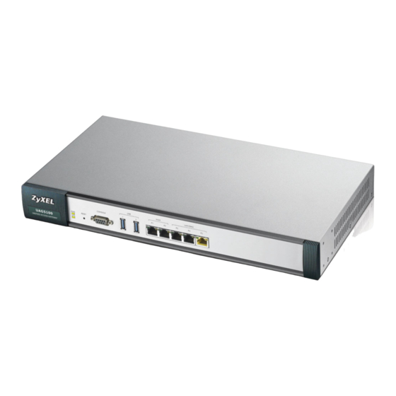
Chapter 2 Hardware Installation and Connection Figure 18 Front Panel: UAG5100 1000Base-T Ports The 1000Base-T auto-negotiating, auto-crossover Ethernet ports support 10/100/1000 Mbps Gigabit Ethernet so the speed can be 100 Mbps or 1000 Mbps. The duplex mode is full at 1000 Mbps and half or full at 10/100 Mbps. -
Page 40: Rear Panel
Chapter 2 Hardware Installation and Connection Table 11 Front Panel LEDs (continued) COLOR STATUS DESCRIPTION Green The UAG is not ready or has failed. The UAG is ready and running. Blinking The UAG is booting. The UAG had an error or has failed. WLAN Green The wireless network is activated. -
Page 41: Uag5100
(COM1, COM2 or other COM port) of your computer. 2.4.2 UAG5100 The following figure shows the rear panel of the UAG. The rear panel contains a connector for the power receptacle. Figure 20 Rear Panel: UAG5100 UAG Series User’s Guide... -
Page 42: Printer Deployment
H A PT ER Printer Deployment 3.1 Overview This chapter shows you how to set up an external statement printer (SP350E for example) and deploy it in your network with the UAG. In the following examples, you will: • Attach the Printer to the UAG. -
Page 43: Allow The Uag To Monitor And Manage The Printer
Chapter 3 Printer Deployment 3.4 Allow the UAG to Monitor and Manage the Printer Before you add the printer to the UAG’s printer list, check the sticker on the printer’s rear panel to see its MAC address. Go to the Dashboard of the UAG web configurator. Open the DHCP Table to find the IP address which is assigned to the printer’s MAC address. - Page 44 Chapter 3 Printer Deployment Go to the Configuration > Printer > General Setting screen. Click Add in the Printer List to create a new entry for your printer. Alternatively, go to the Configuration > Printer > Printer Manager screen and click the Discover Printer icon.
- Page 45 Chapter 3 Printer Deployment After the printer’s IP address is added to the printer list, select the Enable Printer Manager checkbox in the Configuration > Printer > General Setting screen and then click Apply. Go to the Configuration > Printer > Printer Manager screen to check if the UAG can connect to the printer (the printer status is sync success).
-
Page 46: Turn On Web Authentication On The Uag
Chapter 3 Printer Deployment Note: You may need to wait up to 90 seconds for the UAG to synchronize with the printer successfully after you click Apply in the the Configuration > Printer > General Setting screen. 3.5 Turn on Web Authentication on the UAG With web authentication, users need to log in through a designated web page or agree to the policy of user agreement before they can access the network(s). -
Page 47: Generate A Free Guest Account
Chapter 3 Printer Deployment The Auth. Policy Add screen displays. Set Authentication to required and select Force User Authentication to redirect all HTTP traffic to the default login page. Select default-web-portal from the Authentication Type drop-down list box to allow users to authenticate through the default web portal login page. - Page 48 Chapter 3 Printer Deployment Whenever a user tries to access a web page, he/she will be redirected to the default login page. Click the link on the login page to get a free guest account. A Welcome screen displays. Select the free time service. Click OK to generate and show the account information on the web page.
- Page 49 Chapter 3 Printer Deployment Now you can use this account to access the Internet through the UAG for free. UAG Series User’s Guide...
-
Page 50: Installation Setup Wizard
H A PT ER Installation Setup Wizard 4.1 Welcome Screen When you log into the Web Configurator for the first time or when you reset the UAG to its default configuration, the Installation Setup Wizard screen displays. This wizard helps you configure Internet connection settings, wireless security and web authentication settings. - Page 51 Refer to information provided by your ISP to know what to enter in each field. Leave a field blank if you don’t have that information. Note: Enter the Internet access information exactly as your ISP gave it to you. Figure 22 Internet Access: Step 1 (UAG2100/UAG4100) Figure 23 Internet Access: Step 1 (UAG5100) UAG Series User’s Guide...
-
Page 52: Internet Settings: Ethernet
Chapter 4 Installation Setup Wizard • I have two ISPs: (Only for the UAG that has multiple WAN interfaces.) Select this option to configure two Internet connections. Leave it cleared to configure just one. This option appears when you are configuring the first WAN interface. •... -
Page 53: Internet Settings: Pppoe
Chapter 4 Installation Setup Wizard • First / Second DNS Server: These fields display if you selected static IP address assignment. The Domain Name System (DNS) maps a domain name to an IP address and vice versa. Enter a DNS server's IP address(es). The DNS server is extremely important because without it, you must know the IP address of a computer before you can access it. -
Page 54: Internet Settings: Pptp
Chapter 4 Installation Setup Wizard • Select Nailed-Up if you do not want the connection to time out. Otherwise, type the Idle Timeout in seconds that elapses before the router automatically disconnects from the PPPoE server. WAN IP Address Assignments •... -
Page 55: Internet Settings - Second Wan Interface
Chapter 4 Installation Setup Wizard ISP Parameters • Authentication Type - Select an authentication protocol for outgoing calls. Options are: • CHAP/PAP - Your UAG accepts either CHAP or PAP when requested by the remote node. • CHAP - Your UAG accepts CHAP only. •... -
Page 56: Wireless Settings
Chapter 4 Installation Setup Wizard 4.3 Wireless Settings Use this screen to turn on the controller feature and allow the UAG to manage the connected APs. Figure 27 Wireless Settings 4.3.1 Wireless and Radio Settings Use this screen to configure the wireless and wireless security settings when you turn on the local The screen varies depending on the security mode you selected. -
Page 57: Web Authentication Settings
Chapter 4 Installation Setup Wizard Wireless Settings • SSID - Enter a descriptive name of up to 32 printable characters for the wireless LAN. • Security Mode - Select wep, wpa2 or wpa2-mix to add security on this wireless network. Otherwise, select none to allow any wireless client to associate this network without authentication. -
Page 58: Printer Settings
Chapter 4 Installation Setup Wizard To block all network traffic or traffic received on a specific interface, use the Configuration > Web Authentication screens (Section 23.2 on page 260) to configure a new policy. Figure 29 Web Authentication Settings 4.5 Printer Settings If you enable the web authentication feature, attach a statement printer and select Yes to have the UAG generate dynamic guest accounts. -
Page 59: Printer List And Printout Settings
Chapter 4 Installation Setup Wizard 4.5.1 Printer List and Printout Settings Use this screen to view information about the connected statement printer, such as SP350E. Figure 31 Printer List and Printout Settings Printer List • If there is a statement printer attached to the UAG, click Discover Printer to detect the printer that is connected to the UAG and display the printer information. -
Page 60: Billing Profile
Chapter 4 Installation Setup Wizard Figure 32 Billing Settings Accounting Method • Select Time to Finish to allow each user a one-time login. Once the user logs in, the system starts counting down the pre-defined usage even if the user stops the Internet access before the time period is finished. -
Page 61: Account Generator Settings
Chapter 4 Installation Setup Wizard Figure 33 Billing Profile • Profile Name - Enter a name for the billing profile. You can use up to 31 alphanumeric characters (A-Z, a-z, 0-9) and underscores (_). Spaces are not allowed. The first character must be a letter. -
Page 62: Free Time Settings
Chapter 4 Installation Setup Wizard Figure 34 Account Generator Settings 4.7 Free Time Settings Use this screen to configure the free time settings. Figure 35 Free Time Settings • Free Time Period - Select the duration of time period for which the free time account is allowed to access the Internet. -
Page 63: Device Registration
Chapter 4 Installation Setup Wizard • Maximum Registration Number Before Reset Time - Enter the maximum number of the users that are allowed to log in for Internet access with a free guest account before the time specified in the Reset Time field. For example, if you set the Maximum Registration Number Before Reset Time to 1 and the Reset Time to 13:00, even the first free guest account has expired at 11:30, the second account still cannot access the Internet until 13:00. -
Page 64: Quick Setup Wizards
In the Web Configurator, click Configuration > Quick Setup to open the first Quick Setup screen. Figure 37 Quick Setup (UAG2100/UAG4100) Figure 38 Quick Setup (UAG5100) • WAN Interface Click this link to open a wizard to set up a WAN (Internet) connection. This wizard creates matching ISP account settings in the UAG if you use PPPoE or PPTP. -
Page 65: Wan Interface Quick Setup
Chapter 5 Quick Setup Wizards • VPN Setup Use VPN Setup to configure a VPN (Virtual Private Network) rule for a secure connection to another computer or network. See Section 5.3 on page 5.2 WAN Interface Quick Setup Click WAN Interface in the main Quick Setup screen to open the WAN Interface Quick Setup Wizard Welcome screen. -
Page 66: Configure Wan Ip Settings
Chapter 5 Quick Setup Wizards Otherwise, choose PPPoE or PPTP for a dial-up connection according to the information from your ISP. Figure 41 WAN Interface Setup: Step 2 The screens vary depending on what encapsulation type you use. Refer to information provided by your ISP to know what to enter in each field. - Page 67 Chapter 5 Quick Setup Wizards Assignment to Static and/or select PPTP or PPPoE, enter the Internet access information exactly as your ISP gave it to you. Figure 43 WAN and ISP Connection Settings: (PPTP Shown) The following table describes the labels in this screen. Table 12 WAN and ISP Connection Settings LABEL DESCRIPTION...
-
Page 68: Quick Setup Interface Wizard: Summary
Chapter 5 Quick Setup Wizards Table 12 WAN and ISP Connection Settings (continued) LABEL DESCRIPTION Password Type the password associated with the user name above. Use up to 64 ASCII characters except the [] and ?. This field can be blank. Retype to Type your password again for confirmation. - Page 69 Chapter 5 Quick Setup Wizards Figure 44 Interface Wizard: Summary WAN (Ethernet Shown) The following table describes the labels in this screen. Table 13 Interface Wizard: Summary WAN LABEL DESCRIPTION Encapsulation This displays what encapsulation this interface uses to connect to the Internet. Service Name This field only appears for a PPPoE interface.
-
Page 70: Vpn Setup Wizard
On the UAG that supports VPN, click VPN Setup in the main Quick Setup screen to open the VPN Setup Wizard Welcome screen. Figure 45 VPN Setup Wizard (UAG5100) 5.3.1 Welcome Use wizards to create Virtual Private Network (VPN) rules. After you complete the wizard, the Phase 1 rule settings appear in the VPN >... -
Page 71: Vpn Setup Wizard: Wizard Type
Chapter 5 Quick Setup Wizards 5.3.2 VPN Setup Wizard: Wizard Type Choose Express to create a VPN rule with the default phase 1 and phase 2 settings to connect to another ZLD-based UAG using a pre-shared key. Choose Advanced to change the default settings and/or use certificates instead of a pre-shared key to create a VPN rule to connect to another IPSec device. -
Page 72: Vpn Express Wizard - Configuration
Chapter 5 Quick Setup Wizards Rule Name: Type the name used to identify this VPN connection (and VPN gateway). You may use 1-31 alphanumeric characters, underscores (_), or dashes (-), but the first character cannot be a number. This value is case-sensitive. Application Scenario: This shows the scenario that the UAG supports. -
Page 73: Vpn Express Wizard - Finish
Chapter 5 Quick Setup Wizards Figure 50 VPN Express Wizard: Summary • Rule Name: Identifies the VPN gateway policy. • Secure Gateway: IP address or domain name of the remote IPSec device. • Pre-Shared Key: VPN tunnel password. It identifies a communicating party during a phase 1 IKE negotiation. -
Page 74: Vpn Advanced Wizard - Scenario
Chapter 5 Quick Setup Wizards Figure 51 VPN Express Wizard: Finish Click Close to exit the wizard. 5.3.7 VPN Advanced Wizard - Scenario Click the Advanced radio button as shown in Figure 47 on page 71 to display the following screen. Figure 52 VPN Advanced Wizard: Scenario Rule Name: Type the name used to identify this VPN connection (and VPN gateway). -
Page 75: Vpn Advanced Wizard - Phase 1 Settings
Chapter 5 Quick Setup Wizards Application Scenario: This shows the scenario that the UAG supports. • Site-to-site - The remote IPSec device has a static IP address or a domain name. This UAG can initiate the VPN tunnel. 5.3.8 VPN Advanced Wizard - Phase 1 Settings There are two phases to every IKE (Internet Key Exchange) negotiation –... -
Page 76: Vpn Advanced Wizard - Phase 2
Chapter 5 Quick Setup Wizards • Key Group: DH5 is more secure than DH1 or DH2 (although it may affect throughput). DH1 (default) refers to Diffie-Hellman Group 1 a 768 bit random number. DH2 refers to Diffie-Hellman Group 2 a 1024 bit (1Kb) random number. DH5 refers to Diffie-Hellman Group 5 a 1536 bit random number. -
Page 77: Vpn Advanced Wizard - Summary
Chapter 5 Quick Setup Wizards • Perfect Forward Secrecy (PFS): Disabling PFS allows faster IPSec setup, but is less secure. Select DH1, DH2 or DH5 to enable PFS. DH5 is more secure than DH1 or DH2 (although it may affect throughput). DH1 refers to Diffie-Hellman Group 1 a 768 bit random number. DH2 refers to Diffie-Hellman Group 2 a 1024 bit (1Kb) random number. -
Page 78: Vpn Advanced Wizard - Finish
Chapter 5 Quick Setup Wizards • Pre-Shared Key: VPN tunnel password. • Certificate: The certificate the UAG uses to identify itself when setting up the VPN tunnel. • Local Policy: IP address and subnet mask of the computers on the network behind your UAG that can use the tunnel. - Page 79 Chapter 5 Quick Setup Wizards Figure 56 VPN Wizard: Finish Click Close to exit the wizard. UAG Series User’s Guide...
-
Page 80: Dashboard
H A PT ER Dashboard 6.1 Overview Use the Dashboard screens to check status information about the UAG. 6.1.1 What You Can Do in this Chapter Use the Dashboard screens for the following. • Use the main Dashboard screen (see Section 6.2 on page 80) to see the UAG’s general device information, system status, system resource usage, licensed service status, and interface status. - Page 81 Chapter 6 Dashboard Figure 57 Dashboard C D E The following table describes the labels in this screen. Table 14 Dashboard LABEL DESCRIPTION Widget Settings Use this link to open or close widgets by selecting/clearing the associated checkbox. Up Arrow (B) Click this to collapse a widget.
- Page 82 Chapter 6 Dashboard Table 14 Dashboard (continued) LABEL DESCRIPTION Close Widget (E) Click this to close the widget. Use Widget Setting to re-open it. Virtual Device Select to view the front panel or the rear panel. Hover your cursor over a LED, connected slot or Ethernet port to view details about the status of the UAG’s front panel LEDs and connections.
- Page 83 Chapter 6 Dashboard Table 14 Dashboard (continued) LABEL DESCRIPTION Current Login This field displays the user name used to log in to the current session, the amount of User reauthentication time remaining, and the amount of lease time remaining. Number of This field displays the number of users currently logged in to the UAG.
- Page 84 Chapter 6 Dashboard Table 14 Dashboard (continued) LABEL DESCRIPTION This field displays how the interface gets its IP address. Assignment Static - This interface has a static IP address. DHCP Client - This Ethernet interface gets its IP address from a DHCP server. Dynamic - This PPP interface gets its IP address from a DHCP server.
- Page 85 Chapter 6 Dashboard Table 14 Dashboard (continued) LABEL DESCRIPTION Active This field displays how many traffic sessions are currently open on the UAG. These are all Sessions sessions, established and non-established, that pass through/from/to/within the UAG. Hover your cursor over this field to display icons. Click the Detail icon to go to the Session Monitor screen to see details about the active sessions.
-
Page 86: The Cpu Usage Screen
Chapter 6 Dashboard Table 14 Dashboard (continued) LABEL DESCRIPTION Message This field displays the actual log message. Source This field displays the source address (if any) in the packet that generated the log. Destination This field displays the destination address (if any) in the packet that generated the log. 6.2.1 The CPU Usage Screen Use this screen to look at a chart of the UAG’s recent CPU usage. -
Page 87: The Active Sessions Screen
Chapter 6 Dashboard Figure 59 Dashboard > Memory Usage The following table describes the labels in this screen. Table 16 Dashboard > Memory Usage LABEL DESCRIPTION The y-axis represents the percentage of RAM usage. The x-axis shows the time period over which the RAM usage occurred Refresh Interval Enter how often you want this window to be automatically updated. -
Page 88: The Vpn Status Screen
Chapter 6 Dashboard The following table describes the labels in this screen. Table 17 Dashboard > Show Active Sessions LABEL DESCRIPTION Sessions The y-axis represents the number of session. The x-axis shows the time period over which the session usage occurred Refresh Interval Enter how often you want this window to be automatically updated. -
Page 89: The Number Of Login Users Screen
Chapter 6 Dashboard Figure 62 Dashboard > DHCP Table The following table describes the labels in this screen. Table 19 Dashboard > DHCP Table LABEL DESCRIPTION This field is a sequential value, and it is not associated with a specific entry. Interface This field identifies the interface that assigned an IP address to a DHCP client. - Page 90 Chapter 6 Dashboard Figure 63 Dashboard > Number of Login Users The following table describes the labels in this screen. Table 20 Dashboard > Number of Login Users LABEL DESCRIPTION This field is a sequential value and is not associated with any entry. User ID This field displays the user name of each user who is currently logged in to the UAG.
-
Page 91: Monitor
H A PT ER Monitor 7.1 Overview Use the Monitor screens to check status and statistics information. 7.1.1 What You Can Do in this Chapter Use the Monitor screens for the following. • Use the System Status > Port Statistics screen (see Section 7.2 on page 92) to look at packet statistics for each physical port. -
Page 92: The Port Statistics Screen
Chapter 7 Monitor • Use the Detected Device screen (Section 7.16 on page 116) to view the wireless devices passively detected by the UAG. • Use the Printer Status screen (see Section 7.17 on page 118) to view information about the connected statement printers. -
Page 93: The Port Statistics Graph Screen
Chapter 7 Monitor The following table describes the labels in this screen. Table 21 Monitor > System Status > Port Statistics LABEL DESCRIPTION Poll Interval Enter how often you want this window to be updated automatically, and click Set Interval. Set Interval Click this to set the Poll Interval the screen uses. -
Page 94: The Interface Status Screen
Chapter 7 Monitor Figure 65 Monitor > System Status > Port Statistics > Switch to Graphic View The following table describes the labels in this screen. Table 22 Monitor > System Status > Port Statistics > Switch to Graphic View LABEL DESCRIPTION Refresh Interval... - Page 95 Chapter 7 Monitor Figure 66 Monitor > System Status > Interface Status Each field is described in the following table. Table 23 Monitor > System Status > Interface Status LABEL DESCRIPTION Interface Status If an Ethernet interface does not have any physical ports associated with it, its entry is displayed in light gray text.
- Page 96 Chapter 7 Monitor Table 23 Monitor > System Status > Interface Status (continued) LABEL DESCRIPTION Zone This field displays the zone to which the interface is assigned. IP Addr/Netmask This field displays the current IP address and subnet mask assigned to the interface. If the IP address and subnet mask are 0.0.0.0, the interface is disabled or did not receive an IP address and subnet mask via DHCP.
-
Page 97: The Traffic Statistics Screen
Chapter 7 Monitor 7.4 The Traffic Statistics Screen Click Monitor > System Status > Traffic Statistics to display the Traffic Statistics screen. This screen provides basic information about the following for example: • Most-visited Web sites and the number of times each one was visited. This count may not be accurate in some cases because the UAG counts HTTP GET packets. - Page 98 Chapter 7 Monitor Table 24 Monitor > System Status > Traffic Statistics (continued) LABEL DESCRIPTION Sort By Select the type of report to display. Choices are: Host IP Address/User - displays the IP addresses or users with the most traffic and how much traffic has been sent to and from each one.
-
Page 99: The Session Monitor Screen
Chapter 7 Monitor The following table displays the maximum number of records shown in the report, the byte count limit, and the hit count limit. Table 25 Maximum Values for Reports LABEL DESCRIPTION Maximum Number of Records Byte Count Limit bytes;... - Page 100 Chapter 7 Monitor The following table describes the labels in this screen. Table 26 Monitor > System Status > Session Monitor LABEL DESCRIPTION View Select how you want the information to be displayed. Choices are: sessions by users - display all active sessions grouped by user. sessions by services - display all active sessions grouped by service or protocol.
-
Page 101: The Ddns Status Screen
Chapter 7 Monitor Table 26 Monitor > System Status > Session Monitor (continued) LABEL DESCRIPTION Page x of x This is the number of the page of entries currently displayed and the total number of pages of entries. Type a page number to go to or use the arrows to navigate the pages of entries. Show x items Select how many entries you want to display on each page. -
Page 102: The Login Users Screen
Chapter 7 Monitor Figure 70 Monitor > System Status > IP/MAC Binding The following table describes the labels in this screen. Table 28 Monitor > System Status > IP/MAC Binding LABEL DESCRIPTION Interface Select a UAG interface that has IP/MAC binding enabled to show to which devices it has assigned an IP address. -
Page 103: The Dynamic Guest Screen
Chapter 7 Monitor The following table describes the labels in this screen. Table 29 Monitor > System Status > Login Users LABEL DESCRIPTION Force Logout Select a user ID and click this icon to end a user’s session. Note: You cannot use this button to terminate a user’s session when he/she accesses the UAG through the console port. - Page 104 Chapter 7 Monitor and password. Guest users can log in with the dynamic guest accounts when connecting to an SSID for a specified time unit. Use this screen to look at a list of dynamic guest user accounts on the UAG’s local database.
-
Page 105: The Upnp Port Status Screen
Chapter 7 Monitor The following table describes the icons in this screen. Table 31 Monitor > System Status > Dynamic Guest Icons LABEL DESCRIPTION This guest account is un-used. This guest account is in use and online. This guest account has been used but is offline now. This guest account expired. -
Page 106: The Usb Storage Screen
Chapter 7 Monitor Table 32 Monitor > System Status > UPnP Port Status (continued) LABEL DESCRIPTION Protocol This field displays the protocol of the NAT mapping rule (TCP or UDP). Internal Port This field displays the port number on the Internal Client to which the UAG should forward incoming connection requests. -
Page 107: The Ethernet Neighbor Screen
Chapter 7 Monitor Table 33 Monitor > System Status > USB Storage (continued) LABEL DESCRIPTION Status Ready - you can have the UAG use the USB storage device. Click Remove Now to stop the UAG from using the USB storage device so you can remove it. - Page 108 Chapter 7 Monitor Figure 75 Monitor > System Status > Ethernet Neighbor The following table describes the labels in this screen. Table 34 Monitor > System Status > Ethernet Neighbor LABEL DESCRIPTION Local Port This field displays the port of the UAG, on which the neighboring device is discovered. (Description) For UAGs that support Port Role, if ports 3 to 4 are grouped together and there is a connection to P4 only, the UAG will display P3 as the first interface port number (even...
-
Page 109: The Ap List Screen
Chapter 7 Monitor 7.13 The AP List Screen Use this screen to view which APs are currently connected to the UAG. To access this screen, click Monitor > Wireless > AP Information > AP List. Figure 76 Monitor > Wireless > AP Information > AP List The following table describes the labels in this screen. -
Page 110: Station Count Of Ap
Chapter 7 Monitor Table 35 Monitor > Wireless > AP Information > AP List (continued) LABEL DESCRIPTION LED Status This displays the AP LED status. N/A displays if the AP does not support LED suppression mode and/or have a locator LED to show the actual location of the AP. - Page 111 Chapter 7 Monitor configuration information, port status and station statistics for the connected AP. To access this screen, select an entry and click the More Information button in the AP List screen. Figure 77 Monitor > Wireless > AP Information > AP List > Station Count of AP The following table describes the labels in this screen.
-
Page 112: The Radio List Screen
Chapter 7 Monitor Table 37 Monitor > Wireless > AP Information > AP List > Station Count of AP (continued) LABEL DESCRIPTION Status This displays whether or not the VLAN is activated. This shows the VLAN ID number. Member This field displays the Ethernet port(s) that is a member of this VLAN. Station Count The y-axis represents the number of connected stations. - Page 113 Chapter 7 Monitor Table 38 Monitor > Wireless > AP Information > Radio List (continued) LABEL DESCRIPTION Frequency Band This indicates the wireless frequency currently being used by the radio. This shows - when the radio is in monitor mode. Channel ID This indicates the radio’s channel ID.
-
Page 114: Ap Mode Radio Information
Chapter 7 Monitor 7.14.1 AP Mode Radio Information This screen allows you to view detailed information about a selected radio’s SSID(s), wireless traffic and wireless clients for the preceding 24 hours. To access this window, select an entry and click the More Information button in the Radio List screen. -
Page 115: The Station List Screen
Chapter 7 Monitor The following table describes the labels in this screen. Table 39 Monitor > Wireless > AP Info > Radio List > AP Mode Radio Information LABEL DESCRIPTION MBSSID Detail This list shows information about the SSID(s) that is associated with the radio over the preceding 24 hours. -
Page 116: Detected Device
Chapter 7 Monitor The following table describes the labels in this screen. Table 40 Monitor > Wireless > Station List LABEL DESCRIPTION SSID Name This field displays the SSID name with which at least one station is associated. Click + or - to display or hide details about wireless stations that connected to the SSID. This is the station’s index number in this list. - Page 117 Chapter 7 Monitor Figure 81 Monitor > Wireless > Detected Device The following table describes the labels in this screen. Table 41 Monitor > Wireless > Rogue AP > Detected Device LABEL DESCRIPTION Mark as Rogue Click this button to mark the selected AP as a rogue AP. A rogue AP can be contained in the Configuration >...
-
Page 118: The Printer Status Screen
Chapter 7 Monitor 7.17 The Printer Status Screen This screen displays information about the connected statement printer, such as SP350E. Click Monitor > Printer Status to display this screen. Figure 82 Monitor > Printer Status The following table describes the labels in this screen. Table 42 Monitor >... -
Page 119: Vpn 1-1 Mapping Statistics
Chapter 7 Monitor Figure 83 Monitor > VPN 1-1 Mapping The following table describes the labels in this screen. Table 43 Monitor > VPN 1-1 Mapping LABEL DESCRIPTION Force Logout Select a user ID and click this icon to end a user’s session. This field is a sequential value and is not associated with any entry. -
Page 120: The Ipsec Monitor Screen
Chapter 7 Monitor The following table describes the labels in this screen. Table 44 Monitor > VPN 1-1 Mapping > Statistics LABEL DESCRIPTION This field displays the rule’s index number in the list. Status The activate (light bulb) icon is lit when the entry is active and dimmed when the entry is inactive. -
Page 121: Regular Expressions In Searching Ipsec Sas
Chapter 7 Monitor Table 45 Monitor > VPN Monitor > IPSec (continued) LABEL DESCRIPTION Connectivity Check Select an IPSec SA and click this button to check the connection to the remote IPSec router to make sure it is still available. Page x of x This is the number of the page of entries currently displayed and the total number of pages of entries. - Page 122 Chapter 7 Monitor the use of a particular application’s individual features (like text messaging, voice, video conferencing, and file transfers). Click Monitor > UTM Statistics > App Patrol to display the following screen. This screen displays Application Patrol statistics based on the App Patrol profiles bound to Security Policy profiles. Figure 86 Monitor >...
-
Page 123: The Content Filter Screen
Chapter 7 Monitor Table 46 Monitor > UTM Statistics > App Patrol LABEL DESCRIPTION Inbound Kbps This field displays the amount of the application’s traffic that has gone to the UAG (in kilo bits per second). Outbound Kbps This field displays the amount of the application’s traffic that has gone from the UAG (in kilo bits per second). - Page 124 Chapter 7 Monitor The following table describes the labels in this screen. Table 47 Monitor > UTM Statistics > Content Filter LABEL DESCRIPTION General Settings Collect Statistics Select this check box to have the UAG collect content filtering statistics. The collection starting time displays after you click Apply. All of the statistics in this screen are for the time period starting at the time displayed here.
-
Page 125: The Log Screen
Chapter 7 Monitor 7.22 The Log Screen Log messages are stored in two separate logs, one for regular log messages and one for debugging messages. In the regular log, you can look at all the log messages by selecting All Logs, or you can select a specific category of log messages (for example, Security Policy Control or User). - Page 126 Chapter 7 Monitor Table 48 Monitor > Log (continued) LABEL DESCRIPTION Priority This displays when you show the filter. Select the priority of log messages to display. The log displays the log messages with this priority or higher. Choices are: any, emerg, alert, crit, error, warn, notice, and info, from highest priority to lowest priority.
-
Page 127: View Ap Log
Chapter 7 Monitor Table 48 Monitor > Log (continued) LABEL DESCRIPTION Protocol This field displays the service protocol used by the packet that generated the log message. Note This field displays any additional information about the log message. The Web Configurator saves the filter settings if you leave the View Log screen and return to it later. - Page 128 Chapter 7 Monitor The following table describes the labels in this screen. Table 49 Monitor > Log > View AP Log LABEL DESCRIPTION Show/Hide Filter Click this to show or hide the AP log filter. Select an AP Select an AP from the list and click Query to view its log messages. Log Query This indicates the current log query status.
-
Page 129: Dynamic Users Log
Chapter 7 Monitor Table 49 Monitor > Log > View AP Log (continued) LABEL DESCRIPTION Category This indicates the selected log message’s category. Message This displays content of the selected log message. Source This displays the source IP address of the selected log message. Source Interface This field displays the source interface of the log message. - Page 130 Chapter 7 Monitor Table 50 Monitor > Log > Dynamic Users Log (continued) LABEL DESCRIPTION Clear Log Click this button to delete the log messages for invalid accounts. This is the index number of the dynamic guest account in the list. Status This field displays whether an account expires or not.
-
Page 131: Licensing
APs and the LAN/WLAN users that can connect to the UAG at one time. The UAG2100 can also subscribe to the SMS ticketing service in order to send SMS text messages. The UAG5100 can also use AppPatrol (application patrol), and content filtering subscription services. -
Page 132: Registration Screen
UTM features. Maximum Number of Managed APs The UAG is initially configured to support up to one local AP (NOT available on the UAG5100) and 8 remote managed APs (such as the NWA5123-NI). You can increase this by subscribing to additional licenses. -
Page 133: App Patrol Signature Update Screen
Chapter 8 Licensing Figure 92 Configuration > Licensing > Registration > Service The following table describes the labels in this screen. Table 51 Configuration > Licensing > Registration > Service LABEL DESCRIPTION License Status This is the entry’s position in the list. Service This lists the services that are available on the UAG. - Page 134 Chapter 8 Licensing You need to create an account at myZyXEL.com, register your UAG and then subscribe for application patrol service in order to be able to download new packet inspection signatures from myZyXEL.com (see the Registration screens). Use the Signature Update > App Patrol screen to schedule or immediately download signatures.
- Page 135 Chapter 8 Licensing Table 52 Configuration > Licensing > Signature Update > App Patrol (continued) LABEL DESCRIPTION Hourly Select this option to have the UAG check for new signatures every hour. Daily Select this option to have the UAG check for new signatures everyday at the specified time.
-
Page 136: Wireless
H A PT ER Wireless 9.1 Overview Use the Wireless screens to configure how the UAG manages the Access Points (APs) that are connected to it. 9.1.1 What You Can Do in this Chapter • The Controller screen (Section 9.2 on page 137) sets how the UAG allows new APs to connect to the network. -
Page 137: Controller Screen
Chapter 9 Wireless 9.2 Controller Screen Use this screen to set how the UAG allows new APs to connect to the network. Click Configuration > Wireless > Controller to access this screen. Figure 94 Configuration > Wireless > Controller Each field is described in the following table. Table 53 Configuration >... - Page 138 Chapter 9 Wireless Each field is described in the following table. Table 54 Configuration > Wireless > AP Management LABEL DESCRIPTION Edit Select an AP and click this button to edit its properties. Remove Select one or multiple APs and click this button to remove the AP(s) from the list. Note: If in the Configuration >...
-
Page 139: Edit Ap List
Chapter 9 Wireless 9.3.1 Edit AP List Select an AP and click the Edit button in the Configuration > Wireless > AP Management table to display this screen. Figure 96 Configuration > Wireless > AP Management > Edit AP List Each field is described in the following table. -
Page 140: Port Setting Edit
Chapter 9 Wireless Table 55 Configuration > Wireless > AP Management > Edit AP List (continued) LABEL DESCRIPTION Radio 1/2 OP Mode Select the operating mode for radio 1 or radio 2. AP Mode means the AP can receive connections from wireless clients and pass their data traffic through to the UAG to be managed (or subsequently passed on to an upstream gateway for managing). -
Page 141: Vlan Add/Edit
Chapter 9 Wireless Figure 97 Configuration > Wireless > AP Management > Edit AP List > Edit Port Each field is described in the following table. Table 56 Configuration > Wireless > AP Management > Edit AP List > Edit Port LABEL DESCRIPTION Enable... - Page 142 Chapter 9 Wireless Figure 98 Configuration > Wireless > AP Management > Edit AP List > Edit VLAN Each field is described in the following table. Table 57 Configuration > Wireless > AP Management > Edit AP List > Edit VLAN LABEL DESCRIPTION Enable...
-
Page 143: Ap Policy
Chapter 9 Wireless 9.3.4 AP Policy Use this screen to configure the AP controller’s IP address on the managed APs and determine the action the managed APs take if the current AP controller fails. Click Configuration > Wireless > AP Management > AP Policy to access this screen. Figure 99 Configuration >... -
Page 144: Mon Mode
Chapter 9 Wireless 9.4 MON Mode Use this screen to assign APs either to the rogue AP list or the friendly AP list. A rogue AP is a wireless access point operating in a network’s coverage area that is not under the control of the network administrator, and which can potentially open up holes in a network’s security. -
Page 145: Add/Edit Rogue/Friendly List
Chapter 9 Wireless Table 59 Configuration > Wireless > MON Mode (continued) LABEL DESCRIPTION Role This field indicates whether the selected AP is a rogue-ap or a friendly-ap. To change the AP’s role, click the Edit button. MAC Address This field indicates the AP’s radio MAC address. Description This field displays the AP’s description. -
Page 146: Load Balancing
Chapter 9 Wireless 9.5 Load Balancing Use this screen to configure wireless network traffic load balancing between the APs on your network. Click Configuration > Wireless > Load Balancing to access this screen. Figure 102 Configuration > Wireless > Load Balancing Each field is described in the following table. -
Page 147: Disassociating And Delaying Connections
Chapter 9 Wireless Table 61 Configuration > Wireless > Load Balancing (continued) LABEL DESCRIPTION Apply Click Apply to save your changes back to the UAG. Reset Click Reset to return the screen to its last-saved settings. 9.5.1 Disassociating and Delaying Connections When your AP becomes overloaded, there are two basic responses it can take. -
Page 148: Dcs
Chapter 9 Wireless Figure 104 Kicking a Connection Connections are kicked based on either idle timeout or signal strength. The UAG first looks to see which devices have been idle the longest, then starts kicking them in order of highest idle time. If no connections are idle, the next criteria the UAG analyzes is signal strength. - Page 149 Chapter 9 Wireless Figure 105 Configuration > Wireless > DCS Each field is described in the following table. Table 62 Configuration > Wireless > DCS LABEL DESCRIPTION General Settings Select Now Click this to have the managed APs scan for and select an available channel immediately.
- Page 150 Chapter 9 Wireless Table 62 Configuration > Wireless > DCS (continued) LABEL DESCRIPTION Available This text box lists the channels that are available in the 2.4 GHz band. Select the channels channels that you want the AP to use, and click the right arrow button to add them. Channels This text box lists the channels that you allow the AP to use.
-
Page 151: Auto Healing
Chapter 9 Wireless 9.7 Auto Healing Use this screen to enable auto healing, which allows you to extend the wireless service coverage area of the managed APs when one of the APs fails. Click Configuration > Wireless > Auto Healing to access this screen. Figure 106 Configuration >... -
Page 152: Technical Reference
Chapter 9 Wireless 9.8 Technical Reference The following section contains additional technical information about the features described in this chapter. 9.8.1 Dynamic Channel Selection When numerous APs broadcast within a given area, they introduce the possibility of heightened radio interference, especially if some or all of them are broadcasting on the same radio channel. If the interference becomes too great, then the network administrator must open his AP configuration options and manually change the channel to one that no other AP is using (or at least a channel that has a lower level of interference) in order to give the connected stations a minimum degree of... -
Page 153: Load Balancing
Chapter 9 Wireless Finally, there is an alternative four channel scheme for ETSI, consisting of channels 1, 5, 9, 13. This offers significantly less overlap that the other one. Figure 109 An Alternative Four-Channel Deployment 9.8.2 Load Balancing Because there is a hard upper limit on an AP’s wireless bandwidth, load balancing can be crucial in areas crowded with wireless users. -
Page 154: Interfaces
HAPTER Interfaces 10.1 Interface Overview Use the Interface screens to configure the UAG’s interfaces. You can also create interfaces on top of other interfaces. • Ports are the physical ports to which you connect cables. • Interfaces are used within the system operationally. You use them in configuring various features. -
Page 155: Types Of Interfaces
Chapter 10 Interfaces • Layer-3 virtualization (IP alias, for example) is a kind of interface. Types of Interfaces You can create several types of interfaces in the UAG. • Setting interfaces to the same port role forms a port group. Port groups create a hardware connection between physical ports at the layer-2 (data link, MAC address) level. -
Page 156: Port Role Screen
Chapter 10 Interfaces VLAN interface vlan2 are called vlan2:1, vlan2:2, and so on. You cannot specify the number after the colon(:) in the Web Configurator; it is a sequential number. You can specify the number after the colon if you use the CLI to set up a virtual interface. -
Page 157: Ethernet Summary Screen
Chapter 10 Interfaces Note the following if you are configuring from a computer connected to a lan1, lan2 or dmz port and change the port's role: • A port's IP address varies as its role changes, make sure your computer's IP address is in the same subnet as the UAG's lan1, lan2 or dmz IP address. - Page 158 Chapter 10 Interfaces on page 156), the Ethernet interface is effectively removed from the UAG, but you can still configure it. Ethernet interfaces are similar to other types of interfaces in many ways. They have an IP address, subnet mask, and gateway used to make routing decisions. They restrict the amount of bandwidth and packet size.
-
Page 159: Ethernet Edit
Chapter 10 Interfaces Table 66 Configuration > Network > Interface > Ethernet (continued) LABEL DESCRIPTION IP Address This field displays the current IP address of the interface. If the IP address is 0.0.0.0 (in the IPv4 network), the interface does not have an IP address yet. In the IPv4 network, this screen also shows whether the IP address is a static IP address (STATIC) or dynamically assigned (DHCP). - Page 160 Chapter 10 Interfaces Figure 112 Configuration > Network > Interface > Ethernet > Edit (External Type) UAG Series User’s Guide...
- Page 161 Chapter 10 Interfaces Figure 113 Configuration > Network > Interface > Ethernet > Edit (Internal Type) UAG Series User’s Guide...
- Page 162 Chapter 10 Interfaces This screen’s fields are described in the table below. Table 67 Configuration > Network > Interface > Ethernet > Edit LABEL DESCRIPTION Show Advanced Click this button to display a greater or lesser number of configuration fields. Settings / Hide Advanced Settings General Settings...
- Page 163 Chapter 10 Interfaces Table 67 Configuration > Network > Interface > Ethernet > Edit (continued) LABEL DESCRIPTION Egress Enter the maximum amount of traffic, in kilobits per second, the UAG can send through Bandwidth the interface to the network. Allowed values are 0 - 1048576. Ingress This is reserved for future use.
- Page 164 Chapter 10 Interfaces Table 67 Configuration > Network > Interface > Ethernet > Edit (continued) LABEL DESCRIPTION IP Pool Start Enter the IP address from which the UAG begins allocating IP addresses. If you want to Address assign a static IP address to a specific computer, use the Static DHCP Table. If this field is blank, the Pool Size must also be blank.
-
Page 165: Object References
Chapter 10 Interfaces Table 67 Configuration > Network > Interface > Ethernet > Edit (continued) LABEL DESCRIPTION Enable Logs for Select this option to have the UAG generate a log if a device connected to this interface IP/MAC Binding attempts to use an IP address that is bound to another device’s MAC address. Violation Static DHCP Configure a list of static IP addresses the UAG assigns to computers connected to the... -
Page 166: Add/Edit Dhcp Extended Options
Chapter 10 Interfaces Figure 114 Object References The following table describes labels that can appear in this screen. Table 68 Object References LABEL DESCRIPTION Object Name This identifies the object for which the configuration settings that use it are displayed. Click the object’s name to display the object’s configuration screen in the main window. - Page 167 Chapter 10 Interfaces Figure 115 Configuration > Network > Interface > Ethernet > Edit > Add/Edit Extended Options The following table describes labels that can appear in this screen. Table 69 Configuration > Network > Interface > Ethernet > Edit > Add/Edit Extended Options LABEL DESCRIPTION Option...
-
Page 168: Ppp Interfaces
Chapter 10 Interfaces Table 69 Configuration > Network > Interface > Ethernet > Edit > Add/Edit Extended Options LABEL DESCRIPTION Click this to close this screen and update the settings to the previous Edit screen. Cancel Click Cancel to close the screen. The following table lists the available DHCP extended options (defined in RFCs) on the UAG. -
Page 169: Ppp Interface Summary
Chapter 10 Interfaces Figure 116 Example: PPPoE/PPTP Interfaces PPPoE/PPTP interfaces are similar to other interfaces in some ways. They have an IP address, subnet mask, and gateway used to make routing decisions; they restrict bandwidth and packet size; and they can verify the gateway is available. There are two main differences between PPPoE/ PPTP interfaces and other interfaces. -
Page 170: Ppp Interface Add Or Edit
Chapter 10 Interfaces Each field is described in the table below. Table 71 Configuration > Network > Interface > PPP LABEL DESCRIPTION User Configuration / The UAG comes with the (non-removable) System Default PPP interfaces pre- System Default configured. You can create (and delete) User Configuration PPP interfaces. Click this to create a new user-configured PPP interface. - Page 171 Chapter 10 Interfaces Figure 118 Configuration > Network > Interface > PPP > Add UAG Series User’s Guide...
- Page 172 Chapter 10 Interfaces Each field is explained in the following table. Table 72 Configuration > Network > Interface > PPP > Add LABEL DESCRIPTION Show Advanced Click this button to display a greater or lesser number of configuration fields. Settings / Hide Advanced Settings Create new object Click this button to create an ISP Account that you may use for the ISP settings in this...
- Page 173 Chapter 10 Interfaces Table 72 Configuration > Network > Interface > PPP > Add (continued) LABEL DESCRIPTION IP Address This field is enabled if you select Use Fixed IP Address. Enter the IP address for this interface. Gateway This field is enabled if you select Use Fixed IP Address. Enter the IP address of the gateway.
-
Page 174: Vlan Interfaces
Chapter 10 Interfaces Table 72 Configuration > Network > Interface > PPP > Add (continued) LABEL DESCRIPTION Click OK to save your changes back to the UAG. Cancel Click Cancel to exit this screen without saving. 10.5 VLAN Interfaces A Virtual Local Area Network (VLAN) divides a physical network into multiple logical networks. The standard is defined in IEEE 802.1q. -
Page 175: Vlan Interface Summary Screen
Chapter 10 Interfaces • Traffic inside each VLAN is layer-2 communication (data link layer, MAC addresses). It is handled by the switches. As a result, the new switch is required to handle traffic inside VLAN 2. Traffic is only broadcast inside each VLAN, not each physical network. •... -
Page 176: Vlan Interface Add/Edit
Chapter 10 Interfaces Figure 121 Configuration > Network > Interface > VLAN Each field is explained in the following table. Table 73 Configuration > Network > Interface > VLAN LABEL DESCRIPTION Click this to create a new VLAN interface. Edit Double-click an entry or select it and click Edit to open a screen where you can modify the entry’s settings. - Page 177 Chapter 10 Interfaces or select an entry in the VLAN summary screen and click the Edit icon. The following screen appears. Figure 122 Configuration > Network > Interface > VLAN > Edit UAG Series User’s Guide...
- Page 178 Chapter 10 Interfaces Each field is explained in the following table. Table 74 Configuration > Network > Interface > VLAN > Edit LABEL DESCRIPTION Show Advanced Click this button to display a greater or lesser number of configuration fields. Settings / Hide Advanced Settings General Settings Enable Interface...
- Page 179 Chapter 10 Interfaces Table 74 Configuration > Network > Interface > VLAN > Edit (continued) LABEL DESCRIPTION Interface Parameters Egress Enter the maximum amount of traffic, in kilobits per second, the UAG can send through Bandwidth the interface to the network. Allowed values are 0 - 1048576. Ingress This is reserved for future use.
- Page 180 Chapter 10 Interfaces Table 74 Configuration > Network > Interface > VLAN > Edit (continued) LABEL DESCRIPTION IP Pool Start Enter the IP address from which the UAG begins allocating IP addresses. If you want to Address assign a static IP address to a specific computer, click Add Static DHCP. If this field is blank, the Pool Size must also be blank.
-
Page 181: Bridge Interfaces
Chapter 10 Interfaces Table 74 Configuration > Network > Interface > VLAN > Edit (continued) LABEL DESCRIPTION Enable Logs for Select this option to have the UAG generate a log if a device connected to this VLAN IP/MAC Binding attempts to use an IP address that is bound to another device’s MAC address. Violation Static DHCP Configure a list of static IP addresses the UAG assigns to computers connected to the... -
Page 182: Bridge Overview
Chapter 10 Interfaces Bridge Overview A bridge creates a connection between two or more network segments at the layer-2 (MAC address) level. In the following example, bridge X connects four network segments. When the bridge receives a packet, the bridge records the source MAC address and the port on which it was received in a table. -
Page 183: Bridge Interface Summary
Chapter 10 Interfaces A bridge interface may consist of the following members: • Zero or one VLAN interfaces (and any associated virtual VLAN interfaces) • Any number of Ethernet interfaces (and any associated virtual Ethernet interfaces) When you create a bridge interface, the UAG removes the members’ entries from the routing table and adds the bridge interface’s entries to the routing table. -
Page 184: Bridge Interface Add/Edit
Chapter 10 Interfaces Table 78 Configuration > Network > Interface > Bridge (continued) LABEL DESCRIPTION Activate To turn on an entry, select it and click Activate. Inactivate To turn off an entry, select it and click Inactivate. Create Virtual To open the screen where you can create a virtual interface, select an interface and Interface click Create Virtual Interface. - Page 185 Chapter 10 Interfaces Figure 124 Configuration > Network > Interface > Bridge > Add UAG Series User’s Guide...
- Page 186 Chapter 10 Interfaces Each field is described in the table below. Table 79 Configuration > Network > Interface > Bridge > Edit LABEL DESCRIPTION Show Advanced Click this button to display a greater or lesser number of configuration fields. Settings / Hide Advanced Settings General Settings Enable Interface...
- Page 187 Chapter 10 Interfaces Table 79 Configuration > Network > Interface > Bridge > Edit (continued) LABEL DESCRIPTION Gateway This option appears when Interface Type is external or general. This field is enabled if you select Use Fixed IP Address. Enter the IP address of the gateway. The UAG sends packets to the gateway when it does not know how to route the packet to its destination.
- Page 188 Chapter 10 Interfaces Table 79 Configuration > Network > Interface > Bridge > Edit (continued) LABEL DESCRIPTION First DNS Server Specify the IP addresses up to three DNS servers for the DHCP clients to use. Use one Second DNS of the following ways to specify these IP addresses. Server Third DNS Custom Defined - enter a static IP address.
-
Page 189: Virtual Interfaces
Chapter 10 Interfaces Table 79 Configuration > Network > Interface > Bridge > Edit (continued) LABEL DESCRIPTION Description Enter a description to help identify this static DHCP entry. You can use alphanumeric and ()+/:=?!*#@$_%- characters, and it can be up to 60 characters long. Connectivity Check The interface can regularly check the connection to the gateway you specified to make sure it is still available. -
Page 190: Virtual Interfaces Add/Edit
Chapter 10 Interfaces underlying interface uses. Unlike other interfaces, virtual interfaces do not provide DHCP services, and they do not verify that the gateway is available. 10.7.1 Virtual Interfaces Add/Edit This screen lets you configure IP address assignment and interface parameters for virtual interfaces. -
Page 191: Interface Technical Reference
Chapter 10 Interfaces Table 80 Configuration > Network > Interface > Create Virtual Interface (continued) LABEL DESCRIPTION Egress Enter the maximum amount of traffic, in kilobits per second, the UAG can send through Bandwidth the interface to the network. Allowed values are 0 - 1048576. Ingress This is reserved for future use. -
Page 192: Dhcp Settings
Chapter 10 Interfaces In the example above, if the UAG gets a packet with a destination address of 5.5.5.5, it might not find any entries in the routing table. In this case, the packet is dropped. However, if there is a default router to which the UAG should send this packet, you can specify it as a gateway in one of the interfaces. - Page 193 Chapter 10 Interfaces In the UAG, some interfaces can provide DHCP services to the network. In this case, the interface can be a DHCP relay or a DHCP server. As a DHCP relay, the interface routes DHCP requests to DHCP servers on different networks. You can specify more than one DHCP server.
- Page 194 Chapter 10 Interfaces PPPoE/PPTP Overview Point-to-Point Protocol over Ethernet (PPPoE, RFC 2516) and Point-to-Point Tunneling Protocol (PPTP, RFC 2637) are usually used to connect two computers over phone lines or broadband connections. PPPoE is often used with cable modems and DSL connections. It provides the following advantages: •...
-
Page 195: Trunks
HAPTER Trunks 11.1 Overview Use trunks for WAN traffic load balancing to increase overall network throughput and reliability. Load balancing divides traffic loads between multiple interfaces. This allows you to improve quality of service and maximize bandwidth utilization for multiple ISP links. Maybe you have two Internet connections with different bandwidths. -
Page 196: Load Balancing Algorithms
Chapter 11 Trunks • If that interface’s connection goes down, the UAG can still send its traffic through another interface. • You can define multiple trunks for the same physical interfaces. Load Balancing Algorithms The following sections describe the load balancing algorithms the UAG can use to decide which interface the traffic (from the LAN) should use for a session . - Page 197 Chapter 11 Trunks given an equal amount of bandwidth, and then moves to the end of the list; and so on, depending on the number of queues being used. This works in a looping fashion until a queue is empty. The Weighted Round Robin (WRR) algorithm is best suited for situations when the bandwidths set for the two WAN interfaces are different.
-
Page 198: The Trunk Summary Screen
Chapter 11 Trunks 11.2 The Trunk Summary Screen Click Configuration > Network > Interface > Trunk to open the Trunk screen. This screen lists the configured trunks and the load balancing algorithm that each is configured to use. Figure 130 Configuration > Network > Interface > Trunk The following table describes the items in this screen. -
Page 199: Configuring A User-Defined Trunk
Chapter 11 Trunks Table 85 Configuration > Network > Interface > Trunk (continued) LABEL DESCRIPTION User Configuration The UAG automatically adds all external interfaces into the pre-configured system / System Default default SYSTEM_DEFAULT_WAN_TRUNK. You cannot delete it. You can create your own User Configuration trunks and customize the algorithm, member interfaces and the active/passive mode. - Page 200 Chapter 11 Trunks Each field is described in the table below. Table 86 Configuration > Network > Interface > Trunk > Add (or Edit) LABEL DESCRIPTION Name This is read-only if you are editing an existing trunk. When adding a new trunk, enter a descriptive name for this trunk.
-
Page 201: Configuring The System Default Trunk
Chapter 11 Trunks Table 86 Configuration > Network > Interface > Trunk > Add (or Edit) (continued) LABEL DESCRIPTION Egress This field displays with the least load first or spillover load balancing algorithm. It displays Bandwidth the maximum number of kilobits of data the UAG is to send out through the interface per second. - Page 202 Chapter 11 Trunks Each field is described in the table below. Table 87 Configuration > Network > Interface > Trunk > Edit (System Default) LABEL DESCRIPTION Name This field displays the name of the selected system default trunk. Load Balancing Select the load balancing method to use for the trunk.
-
Page 203: Policy And Static Routes
HAPTER Policy and Static Routes 12.1 Policy and Static Routes Overview Use policy routes and static routes to override the UAG’s default routing behavior in order to send packets through the appropriate interface. For example, the next figure shows a computer (A) connected to the UAG’s LAN interface. The UAG routes most traffic from A to the Internet through the UAG’s default gateway (R1). - Page 204 Chapter 12 Policy and Static Routes Policy-based routing is applied to incoming packets on a per interface basis, prior to the normal routing. How You Can Use Policy Routing • Source-Based Routing – Network administrators can use policy-based routing to direct traffic from different users through different connections.
-
Page 205: Policy Route Screen
Chapter 12 Policy and Static Routes DSCP Marking and Per-Hop Behavior DiffServ defines a new DS (Differentiated Services) field to replace the Type of Service (TOS) field in the IP header. The DS field contains a 2-bit unused field and a 6-bit DSCP field which can define up to 64 service levels. - Page 206 Chapter 12 Policy and Static Routes The following table describes the labels in this screen. Table 88 Configuration > Network > Routing > Policy Route LABEL DESCRIPTION Use IPv4 Policy Select this to have the UAG forward packets that match a policy route according to the Route to policy route instead of sending the packets directly to a connected network.
-
Page 207: Policy Route Add/Edit Screen
Chapter 12 Policy and Static Routes Table 88 Configuration > Network > Routing > Policy Route (continued) LABEL DESCRIPTION DSCP Marking This is how the UAG handles the DSCP value of the outgoing packets that match this route. If this field displays a DSCP value, the UAG applies that DSCP value to the route’s outgoing packets. - Page 208 Chapter 12 Policy and Static Routes Figure 135 Configuration > Network > Routing > Policy Route > Add/Edit The following table describes the labels in this screen. Table 89 Configuration > Network > Routing > Policy Route > Add/Edit LABEL DESCRIPTION Show / Hide Click this button to display a greater or lesser number of configuration fields.
- Page 209 Chapter 12 Policy and Static Routes Table 89 Configuration > Network > Routing > Policy Route > Add/Edit (continued) LABEL DESCRIPTION Configuration Enable Select this to activate the policy. Description Enter a descriptive name of up to 31 printable ASCII characters for the policy. Criteria User Select a user name or user group from which the packets are sent.
- Page 210 Chapter 12 Policy and Static Routes Table 89 Configuration > Network > Routing > Policy Route > Add/Edit (continued) LABEL DESCRIPTION Trunk This field displays when you select Trunk in the Type field. Select a trunk group to have the UAG send the packets via the interfaces in the group. Interface This field displays when you select Interface in the Type field.
-
Page 211: Ip Static Route Screen
Chapter 12 Policy and Static Routes Table 89 Configuration > Network > Routing > Policy Route > Add/Edit (continued) LABEL DESCRIPTION Check this Select this to specify a domain name or IP address for the connectivity check. Enter that address domain name or IP address in the field next to it. -
Page 212: Policy Routing Technical Reference
Chapter 12 Policy and Static Routes Figure 137 Configuration > Network > Routing > Static Route > Add The following table describes the labels in this screen. Table 91 Configuration > Network > Routing > Static Route > Add LABEL DESCRIPTION Destination IP This parameter specifies the IP network address of the final destination. - Page 213 Chapter 12 Policy and Static Routes precedence determines the probability that routers in the network will drop packets when congestion occurs. If congestion occurs between classes, the traffic in the higher class (smaller numbered class) is generally given priority. Combining the classes and drop precedence produces the following twelve DSCP encodings from AF11 through AF43.
-
Page 214: Ddns
HAPTER DDNS 13.1 DDNS Overview Dynamic DNS (DDNS) services let you use a domain name with a dynamic IP address. 13.1.1 What You Can Do in this Chapter • Use the DDNS screen (see Section 13.2 on page 215) to view a list of the configured DDNS domain names and their details. -
Page 215: The Ddns Screen
Chapter 13 DDNS 13.2 The DDNS Screen The DDNS screen provides a summary of all DDNS domain names and their configuration. In addition, this screen allows you to add new domain names, edit the configuration for existing domain names, and delete domain names. Click Configuration > Network > DDNS to open the following screen. -
Page 216: The Dynamic Dns Add/Edit Screen
Chapter 13 DDNS Table 94 Configuration > Network > DDNS (continued) LABEL DESCRIPTION Apply Click this button to save your changes to the UAG. Reset Click this button to return the screen to its last-saved settings. 13.2.1 The Dynamic DNS Add/Edit Screen The DDNS Add/Edit screen allows you to add a domain name to the UAG or to edit the configuration of an existing domain name. - Page 217 Chapter 13 DDNS Table 95 Configuration > Network > DDNS > Add (continued) LABEL DESCRIPTION Profile Name When you are adding a DDNS entry, type a descriptive name for this DDNS entry in the UAG. You may use 1-31 alphanumeric characters, underscores( ), or dashes (-), but the first character cannot be a number.
- Page 218 Chapter 13 DDNS Table 95 Configuration > Network > DDNS > Add (continued) LABEL DESCRIPTION IP Address The options available in this field vary by DDNS provider. Interface -The UAG uses the IP address of the specified interface. This option appears when you select a specific interface in the Backup Binding Address Interface field.
-
Page 219: Nat
HAPTER 14.1 NAT Overview NAT (Network Address Translation - NAT, RFC 1631) is the translation of the IP address of a host in a packet. For example, the source address of an outgoing packet, used within one network is changed to a different IP address known within another network. Use Network Address Translation (NAT) to make computers on a private network behind the UAG available outside the private network. -
Page 220: The Nat Screen
Chapter 14 NAT 14.2 The NAT Screen The NAT summary screen provides a summary of all NAT rules and their configuration. In addition, this screen allows you to create new NAT rules and edit and delete existing NAT rules. To access this screen, login to the Web Configurator and click Configuration >... -
Page 221: The Nat Add/Edit Screen
Chapter 14 NAT Table 96 Configuration > Network > NAT (continued) LABEL DESCRIPTION Protocol This field displays the service used by the packets for this NAT entry. It displays any if there is no restriction on the services. Original Port This field displays the original destination port(s) of packets for the NAT entry. - Page 222 Chapter 14 NAT Table 97 Configuration > Network > NAT > Add (continued) LABEL DESCRIPTION Rule Name Type in the name of the NAT rule. The name is used to refer to the NAT rule. You may use 1-31 alphanumeric characters, underscores( ), or dashes (-), but the first character cannot be a number.
- Page 223 Chapter 14 NAT Table 97 Configuration > Network > NAT > Add (continued) LABEL DESCRIPTION Port Mapping Type Use the drop-down list box to select how many original destination ports this NAT rule supports for the selected destination IP address (Original IP). Choices are: Any - this NAT rule supports all the destination ports.
-
Page 224: Nat Technical Reference
Chapter 14 NAT 14.3 NAT Technical Reference Here is more detailed information about NAT on the UAG. NAT Loopback Suppose an NAT 1:1 rule maps a public IP address to the private IP address of a LAN SMTP e-mail server to give WAN users access. NAT loopback allows other users to also use the rule’s original IP to access the mail server. - Page 225 Chapter 14 NAT Figure 144 LAN to LAN Traffic Source 172.16.0.1 Source 172.16.0.89 SMTP SMTP 172.16.0.89 172.16.0.21 The LAN SMTP server replies to the UAG’s LAN IP address and the UAG changes the source address to 1.1.1.1 before sending it to the LAN user. The return traffic’s source matches the original destination address (1.1.1.1).
-
Page 226: Vpn 1-1 Mapping
HAPTER VPN 1-1 Mapping 15.1 VPN 1-1 Mapping Overview VPN 1-1 mapping allows an authenticated user in your network to access the Internet or an external server using a public IP address different from the one used by the UAG’s WAN interface. With VPN 1-1 mapping, each user that logs into the UAG and matches a pre-configured mapping rule can obtain an individual public IP address. -
Page 227: The Vpn 1-1 Mapping General Screen
Chapter 15 VPN 1-1 Mapping Security Policy Policy Route VPN 1-1 Mapping If you set a policy route to the same user/user group as a VPN 1-1 mapping rule, the UAG checks the policy routing rules first and forwards the traffic to a specified next-hop if matched. You need to make sure there is no security policy(ies) blocking the traffic from the matched user or user group. -
Page 228: The Vpn 1-1 Mapping Edit Screen
Chapter 15 VPN 1-1 Mapping Table 98 Configuration > Network > VPN 1-1 Mapping (continued) LABEL DESCRIPTION Edit Double-click an entry or select it and click Edit to open a screen where you can modify the entry’s settings. Remove To remove an entry, select it and click Remove. The UAG confirms you want to remove it before doing so. -
Page 229: The Vpn 1-1 Mapping Profile Screen
Chapter 15 VPN 1-1 Mapping The following table describes the labels in this screen. Table 99 Network > VPN 1-1 Mapping > Add LABEL DESCRIPTION Create New Click this button to create any new user/group objects that you need to use in this screen. Object Enable Policy Use this option to turn the VPN 1-1 mapping rule on or off. - Page 230 Chapter 15 VPN 1-1 Mapping The following table describes the labels in this screen. Table 100 Configuration > Network > VPN 1-1 Mapping > Profile LABEL DESCRIPTION Click this to add an entry to the table. If you click Add without selecting an entry in advance then the new entry appears as the first entry.
-
Page 231: Http Redirect
HAPTER HTTP Redirect 16.1 Overview HTTP redirect forwards the client’s HTTP request (except HTTP traffic destined for the UAG) to a web proxy server. In the following example, proxy server A is connected to the lan2 interface in the LAN2 zone. When a client connected to the lan1 interface in the LAN1 zone wants to open a web page, its HTTP request is redirected to proxy server A first. -
Page 232: The Http Redirect Screen
Chapter 16 HTTP Redirect A client connects to a web proxy server each time he/she wants to access the Internet. The web proxy provides caching service to allow quick access and reduce network usage. The proxy checks its local cache for the requested web resource first. If it is not found, the proxy gets it from the specified server and forwards the response to the client. -
Page 233: The Http Redirect Edit Screen
Chapter 16 HTTP Redirect Figure 151 Configuration > Network > HTTP Redirect The following table describes the labels in this screen. Table 101 Configuration > Network > HTTP Redirect LABEL DESCRIPTION Click this to create a new entry. Edit Double-click an entry or select it and click Edit to open a screen where you can modify the entry’s settings. - Page 234 Chapter 16 HTTP Redirect The following table describes the labels in this screen. Table 102 Network > HTTP Redirect > Edit LABEL DESCRIPTION Enable Use this option to turn the HTTP redirect rule on or off. Name Enter a name to identify this rule. You may use 1-31 alphanumeric characters, underscores( ), or dashes (-), but the first character cannot be a number.
-
Page 235: Smtp Redirect
HAPTER SMTP Redirect 17.1 Overview SMTP redirect forwards the authenticated client’s SMTP message to a SMTP server, that handles all outgoing e-mail messages. In the following example, SMTP server A is connected to the lan2 interface in the LAN2 zone. When a client connected to the lan1 interface in the LAN1 zone logs into the UAG and wants to send an e-mail, its SMTP message is redirected to SMTP server A. -
Page 236: The Smtp Redirect Screen
Chapter 17 SMTP Redirect server. The older POP2 requires SMTP for sending messages while the newer POP3 can be used with or without it. This is why many e-mail applications require you to specify both the SMTP server and the POP or IMAP server (even though they may actually be the same server). SMTP Redirect, Security Policy and Policy Route With SMTP redirect, the relevant packet flow for SMTP traffic is: Security Policy... -
Page 237: The Smtp Redirect Edit Screen
Chapter 17 SMTP Redirect Figure 154 Configuration > Network > SMTP Redirect The following table describes the labels in this screen. Table 103 Configuration > Network > SMTP Redirect LABEL DESCRIPTION Enable SMTP Select this option to turn on the SMTP redirect feature on the UAG. Redirect Click this to create a new entry. - Page 238 Chapter 17 SMTP Redirect Figure 155 Network > SMTP Redirect > Edit The following table describes the labels in this screen. Table 104 Network > SMTP Redirect > Edit LABEL DESCRIPTION Enable Use this option to turn the SMTP redirect rule on or off. User Use the drop-down list box to select the individual user or user group for which you want to use this rule.
-
Page 239: Alg
HAPTER 18.1 ALG Overview Application Layer Gateway (ALG) allows the following application to operate properly through the UAG’s NAT. • FTP - File Transfer Protocol - an Internet file transfer service. The ALG feature is only needed for traffic that goes through the UAG’s NAT. 18.1.1 What You Can Do in this Chapter Use the ALG screen (Section 18.2 on page... -
Page 240: Before You Begin
Chapter 18 ALG 18.1.3 Before You Begin You must also configure the security policies and enable NAT in the UAG to allow sessions initiated from the WAN. 18.2 The ALG Screen Click Configuration > Network > ALG to open the ALG screen. Use this screen to turn the ALG off or on, configure the port numbers to which it applies. -
Page 241: Upnp
HAPTER UPnP 19.1 Overview The UAG supports both UPnP and NAT-PMP to permit networking devices to discover each other and connect seamlessly. Universal Plug and Play (UPnP) is a distributed, open networking standard that uses TCP/IP for simple peer-to-peer network connectivity between devices. A UPnP device can dynamically join a network, obtain an IP address, convey its capabilities and learn about other devices on the network. -
Page 242: Cautions With Upnp
Chapter 19 UPnP 19.2.2 Cautions with UPnP The automated nature of NAT traversal applications in establishing their own services and opening security policy ports may present network security issues. Network information and configuration may also be obtained and modified by users in some network environments. When a UPnP device joins a network, it announces its presence with a multicast message. -
Page 243: Technical Reference
Chapter 19 UPnP The following table describes the fields in this screen. Table 106 Configuration > Network > UPnP LABEL DESCRIPTION Enable UPnP Select this check box to activate UPnP on the UAG. Be aware that anyone could use a UPnP application to open the web configurator's login screen without entering the UAG's IP address (although you must still enter the password to access the web configurator). - Page 244 Chapter 19 UPnP Figure 158 Network Connections In the Internet Connection Properties window, click Settings to see the port mappings there were automatically created. Figure 159 Internet Connection Properties You may edit or delete the port mappings or click Add to manually add port mappings. Figure 160 Internet Connection Properties: Advanced Settings UAG Series User’s Guide...
-
Page 245: Web Configurator Easy Access
Chapter 19 UPnP Figure 161 Internet Connection Properties: Advanced Settings: Add Note: When the UPnP-enabled device is disconnected from your computer, all port mappings will be deleted automatically. Select Show icon in notification area when connected option and click OK. An icon displays in the system tray. - Page 246 Chapter 19 UPnP Select My Network Places under Other Places. Figure 164 Network Connections An icon with the description for each UPnP-enabled device displays under Local Network. Right-click on the icon for your UAG and select Invoke. The web configurator login screen displays. Figure 165 Network Connections: My Network Places Right-click on the icon for your UAG and select Properties.
- Page 247 Chapter 19 UPnP Figure 166 Network Connections: My Network Places: Properties: Example UAG Series User’s Guide...
-
Page 248: Ip/Mac Binding
HAPTER IP/MAC Binding 20.1 IP/MAC Binding Overview IP address to MAC address binding helps ensure that only the intended devices get to use privileged IP addresses. The UAG uses DHCP to assign IP addresses and records to MAC address it assigned each IP address. -
Page 249: Ip/Mac Binding Summary
Chapter 20 IP/MAC Binding Interfaces Used With IP/MAC Binding IP/MAC address bindings are grouped by interface. You can use IP/MAC binding with Ethernet, bridge, VLAN interfaces. You can also enable or disable IP/MAC binding and logging in an interface’s configuration screen. 20.2 IP/MAC Binding Summary Click Configuration >... -
Page 250: Ip/Mac Binding Edit
Chapter 20 IP/MAC Binding 20.2.1 IP/MAC Binding Edit Click Configuration > Network > IP/MAC Binding > Edit to open the IP/MAC Binding Edit screen. Use this screen to configure an interface’s IP to MAC address binding settings. Figure 169 Configuration > Network > IP/MAC Binding > Edit The following table describes the labels in this screen. -
Page 251: Static Dhcp Edit
Chapter 20 IP/MAC Binding Table 108 Configuration > Network > IP/MAC Binding > Edit (continued) LABEL DESCRIPTION Description This helps identify the entry. Click OK to save your changes back to the UAG. Cancel Click Cancel to exit this screen without saving. 20.2.2 Static DHCP Edit Click Configuration >... - Page 252 Chapter 20 IP/MAC Binding Figure 171 Configuration > Network > IP/MAC Binding > Exempt List The following table describes the labels in this screen. Table 110 Configuration > Network > IP/MAC Binding > Exempt List LABEL DESCRIPTION Click this to create a new entry. Edit Click an entry or select it and click Edit to modify the entry’s settings.
-
Page 253: Layer 2 Isolation
HAPTER Layer 2 Isolation 21.1 Overview Layer-2 isolation is used to prevent connected devices from communicating with each other in the UAG’s local network(s), except for the devices in the white list, when layer-2 isolation is enabled on the UAG and the local interface(s). Note: The security policy control must be enabled before you can use layer-2 isolation. -
Page 254: Layer-2 Isolation General Screen
Chapter 21 Layer 2 Isolation 21.2 Layer-2 Isolation General Screen This screen allows you to enable Layer-2 isolation on the UAG and specific internal interface(s). To access this screen click Configuration > Network > Layer 2 Isolation. Figure 173 Configuration > Network > Layer 2 Isolation The following table describes the labels in this screen. -
Page 255: Add/Edit White List Rule
Chapter 21 Layer 2 Isolation Figure 174 Configuration > Network > Layer 2 Isolation > White List The following table describes the labels in this screen. Table 112 Configuration > Network > Layer 2 Isolation > White List LABEL DESCRIPTION Enable White List Select this option to turn on the white list on the UAG. - Page 256 Chapter 21 Layer 2 Isolation Figure 175 Configuration > Network > Layer 2 Isolation > White List > Add/Edit The following table describes the labels in this screen. Table 113 Configuration > Network > Layer 2 Isolation > White List > Add/Edit LABEL DESCRIPTION Enable...
-
Page 257: Ipnp
HAPTER IPnP 22.1 Overview IP Plug and Play (IPnP) allows a computer to access the Internet without changing the network settings (such as IP address and subnet mask) of the computer, even when the IP addresses of the computer and the UAG are not in the same subnet. When you disable the IPnP feature, only computers with dynamic IP addresses or static IP addresses in the same subnet as the UAG’s LAN IP address can connect to the UAG or access the Internet through the UAG. -
Page 258: Ipnp Screen
Chapter 22 IPnP 22.2 IPnP Screen This screen allows you to enable IPnP on the UAG and specific internal interface(s). To access this screen click Configuration > Network > IPnP. Figure 177 Configuration > Network > IPnP The following table describes the labels in this screen. Table 114 Configuration >... -
Page 259: Web Authentication
HAPTER Web Authentication 23.1 Overview Web authentication can intercepts network traffic, according to the authentication policies, until the user authenticates his or her connection, usually through a specifically designated login web page or user agreement page. This means all web page requests can initially be redirected to a special web page that requires users to authenticate their sessions. -
Page 260: What You Need To Know
Chapter 23 Web Authentication • Use the Configuration > Web Authentication > Advertisement screens (Section 23.4 on page 283) to enable and set advertisement links. 23.1.2 What You Need to Know Forced User Authentication Instead of making users for which user-aware policies have been configured go to the UAG Login screen manually, you can configure the UAG to display the Login screen automatically whenever it routes HTTP traffic for anyone who has not logged in yet. - Page 261 Chapter 23 Web Authentication Figure 179 Configuration > Web Authentication: General The following table gives an overview of the objects you can configure. Table 115 Configuration > Web Authentication: General LABEL DESCRIPTION Global Setting Enable Web Select the check box to turn on the web authentication feature. Otherwise, clear the check Authentication box to turn it off.
- Page 262 Chapter 23 Web Authentication Table 115 Configuration > Web Authentication: General (continued) LABEL DESCRIPTION Exceptional Use this table to list services that users can access without logging in. Services Click Add to change the list’s membership. A screen appears. Available services appear on the left.
- Page 263 Chapter 23 Web Authentication Table 115 Configuration > Web Authentication: General (continued) LABEL DESCRIPTION Authentication This field displays the authentication requirement for users when their traffic matches this policy. unnecessary - Users do not need to be authenticated. required - Users need to be authenticated. They must manually go to the login screen or or user agreement page.
-
Page 264: User-Aware Access Control Example
Chapter 23 Web Authentication The following table gives an overview of the objects you can configure. Table 116 Configuration > Web Authentication > Add LABEL DESCRIPTION Create new Use to configure any new settings objects that you need to use in this screen. Object Enable Policy Select this check box to activate the authentication policy. - Page 265 Chapter 23 Web Authentication 23.2.2.1 Set Up User Accounts Set up user accounts in the RADIUS server. This example uses the Web Configurator. If you can export user names from the RADIUS server to a text file, then you might configure a script to create the user accounts instead.
- Page 266 Chapter 23 Web Authentication Figure 183 Configuration > Object > User/Group > Group > Add Repeat this process to set up the remaining user groups. 23.2.2.3 Set Up User Authentication Using the RADIUS Server This step sets up user authentication using the RADIUS server. First, configure the settings for the RADIUS server.
- Page 267 Chapter 23 Web Authentication Figure 184 Configuration > Object > AAA Server > RADIUS > Add Click Configuration > Object > Auth. Method. Double-click the default entry. Click the Add icon. Select group radius because the UAG should use the specified RADIUS server for authentication.
- Page 268 Chapter 23 Web Authentication Figure 186 Configuration > Web Authentication In the Web Authentication Policy Summary section, click the Add icon to set up a default policy that has priority over other policies and forces every user to log into the UAG before the UAG routes traffic for them.
- Page 269 Chapter 23 Web Authentication Figure 187 Configuration > Web Authentication: General: Add When the users try to browse the web (or use any HTTP application), the login screen appears. They have to log in using the user name and password in the RADIUS server. 23.2.2.4 User Group Authentication Using the RADIUS Server The previous example showed how to have a RADIUS server authenticate individual user accounts.
- Page 270 Chapter 23 Web Authentication Figure 188 Configuration > Object > AAA Server > RADIUS > Add Now you add ext-group-user user objects to identify groups based on the group identifier values. Set up one user account for each group of user accounts in the RADIUS server. Click Configuration >...
-
Page 271: Authentication Type Screen
Chapter 23 Web Authentication Figure 189 Configuration > Object > User/Group > User > Add Repeat this process to set up the remaining groups of user accounts. 23.2.3 Authentication Type Screen Use this screen to view, create and manage the authentication type profiles on the UAG. An authentication type profile decides which type of web authentication pages to be used for user authentication. - Page 272 Chapter 23 Web Authentication The following table describes the labels in this screen. Table 117 Configuration > Web Authentication: Authentication Type LABEL DESCRIPTION Click this to create a new entry. Select an entry and click Add to create a new entry after the selected entry.
- Page 273 Chapter 23 Web Authentication Figure 191 Configuration > Web Authentication: Authentication Type: Add/Edit (Web Portal) UAG Series User’s Guide...
- Page 274 Chapter 23 Web Authentication Figure 192 Configuration > Web Authentication: Authentication Type: Add/Edit (User Agreement) The following table describes the labels in this screen. Table 118 Configuration > Web Authentication: Authentication Type: Add/Edit LABEL DESCRIPTION Type Select the type of the web authentication page through which users authenticate their connections.
- Page 275 Chapter 23 Web Authentication Table 118 Configuration > Web Authentication: Authentication Type: Add/Edit (continued) LABEL DESCRIPTION External Web Select this to use a custom login page from an external web portal instead of the one Portal uploaded to the UAG. You can configure the look and feel of the web portal page. Login URL Specify the login page’s URL;...
-
Page 276: Custom Web Portal / User Agreement File Screen
Chapter 23 Web Authentication Table 118 Configuration > Web Authentication: Authentication Type: Add/Edit (continued) LABEL DESCRIPTION Welcome URL Specify the welcome page’s URL; for example, http://IIS server IP Address/welcome.html. The Internet Information Server (IIS) is the web server on which the user agreement files are installed. -
Page 277: Walled Garden
Chapter 23 Web Authentication Figure 194 Configuration > Web Authentication: Custom User Agreement File The following table describes the labels in this screen. Table 119 Configuration > Web Authentication: Custom Web Portal / User Agreement File LABEL DESCRIPTION Remove Click a file’s row to select it and and click Remove to delete it from the UAG. Download Click a file’s row to select it and and click Download to save the zipped file to your computer. -
Page 278: General Screen
Chapter 23 Web Authentication 23.3.1 General Screen Use this screen to turn on the walled garden feature. Note: You must enable web authentication before you can access the Walled Garden screens. Note: You can configure up to 20 walled garden web site links. Click Configuration >... - Page 279 Chapter 23 Web Authentication Figure 196 Configuration > Web Authentication > Walled Garden: URL Base The following table describes the labels in this screen. Table 121 Configuration > Web Authentication > Walled Garden: URL Based LABEL DESCRIPTION Walled Garden Use this table to manage the list of walled garden web site links. URL List Click this to create a new entry.
-
Page 280: Domain/Ip Base Screen
Chapter 23 Web Authentication Figure 197 Configuration > Web Authentication > Walled Garden: URL Base: Add/Edit The following table describes the labels in this screen. Table 122 Configuration > Web Authentication > Walled Garden: URL Base: Add/Edit LABEL DESCRIPTION Enable Select this to activate the entry. - Page 281 Chapter 23 Web Authentication Figure 198 Configuration > Web Authentication > Walled Garden: Domain/IP Base The following table describes the labels in this screen. Table 123 Configuration > Web Authentication > Walled Garden: Domain/IP Based LABEL DESCRIPTION Walled Garden Use this table to manage the list of walled garden web site links. Domain/IP List Click this to create a new entry.
-
Page 282: Walled Garden Login Example
Chapter 23 Web Authentication Figure 199 Configuration > Web Authentication > Walled Garden: Domain/IP Base: Add/Edit The following table describes the labels in this screen. Table 124 Configuration > Web Authentication > Walled Garden: Domain/IP Base: Add/Edit LABEL DESCRIPTION Enable Select this to activate the entry. -
Page 283: Advertisement Screen
Chapter 23 Web Authentication Figure 200 Walled Garden Login Example 23.4 Advertisement Screen Use this screen to set the UAG to display an advertisement web page as the first web page whenever the user connects to the Internet. Click Configuration > Web Authentication > Advertisement to display the screen. Figure 201 Configuration >... -
Page 284: Adding/Editing An Advertisement Url
Chapter 23 Web Authentication The following table gives an overview of the objects you can configure. Table 125 Configuration > Web Authentication > Advertisement LABEL DESCRIPTION Enable Select this to turn on the advertisement feature. Advertisement Note: This feature works only when you enable web authentication. Advertisement Use this table to manage the list of advertisement web pages. - Page 285 Chapter 23 Web Authentication The following table gives an overview of the objects you can configure. Table 126 Configuration > Web Authentication > Advertisement > Add/Edit LABEL DESCRIPTION Name Enter a descriptive name for the advertisement web site. You can use up to 31 alphanumeric characters (A-Z, a-z, 0-9) and underscores (_). Spaces are not allowed.
-
Page 286: Rtls
HAPTER RTLS 24.1 Overview Ekahau RTLS (Real Time Location Service) tracks battery-powered Wi-Fi tags attached to APs managed by the UAG to create maps, alerts, and reports. The Ekahau RTLS Controller is the centerpiece of the RTLS system. This server software runs on a Windows computer to track and locate Ekahau tags from Wi-Fi signal strength measurements. -
Page 287: Before You Begin
Chapter 24 RTLS 24.2 Before You Begin You need: • At least three APs managed by the UAG (the more APs the better since it increases the amount of information the Ekahau RTLS Controller has for calculating the location of the tags) •... - Page 288 Chapter 24 RTLS The following table describes the labels in this screen. Table 128 Configuration > RTLS LABEL DESCRIPTION Enable Select this to use Wi-Fi to track the location of Ekahau Wi-Fi tags. IP Address Specify the IP address of the Ekahau RTLS Controller. Server Port Specify the server port number of the Ekahau RTLS Controller.
-
Page 289: Security Policy
HAPTER Security Policy 25.1 Overview A security policy is a template of security settings that can be applied to specific traffic at specific times. The policy can be applied: • to a specific direction of travel of packets (from / to) •... -
Page 290: What You Need To Know
Chapter 25 Security Policy 25.1.2 What You Need to Know Stateful Inspection The UAG uses stateful inspection in its security policies. The UAG restricts access by screening data packets against defined access rules. It also inspects sessions. For example, traffic from one zone is not allowed unless it is initiated by a computer in another zone first. -
Page 291: Security Policy Control Screen
Chapter 25 Security Policy service control (remote management). The UAG checks the security policies before the service control rules for traffic destined for the UAG. A From Any To Device direction rule applies to traffic from an interface which is not in a zone. Global Security Policies Security policies with from any and/or to any as the packet direction are called global security policies. -
Page 292: Configuring The Security Policy Control Screen
Chapter 25 Security Policy and the backup gateway on separate subnets. Virtual interfaces allow you to partition your network into logical sections over the same interface. See the chapter about interfaces for more information. By putting LAN 1 and the alternate gateway (A in the figure) in different subnets, all returning network traffic must pass through the UAG to the LAN. - Page 293 Chapter 25 Security Policy Figure 207 Configuration > Security Policy > Policy Control The following table describes the labels in this screen. Table 130 Configuration > Security Policy > Policy Control LABEL DESCRIPTION General Settings Enable Policy Select this check box to activate security policy control. The UAG performs access control Control when this is activated.
-
Page 294: Add/Edit Policy Control Rule
Chapter 25 Security Policy Table 130 Configuration > Security Policy > Policy Control (continued) LABEL DESCRIPTION Inactivate To turn off an entry, select it and click Inactivate. Move To change a rule’s position in the numbered list, select the rule and click Move to display a field to type a number for where you want to put that rule and press [ENTER] to move the rule to the number that you typed. - Page 295 Chapter 25 Security Policy Figure 208 Configuration > Security Policy > Policy Control > Add The following table describes the labels in this screen. Table 131 Configuration > Security Policy > Policy Control > Add/Edit LABEL DESCRIPTION Create new Use to configure any new settings objects that you need to use in this screen. Object Enable Select this check box to activate the security policy.
-
Page 296: Session Control Screen
Chapter 25 Security Policy Table 131 Configuration > Security Policy > Policy Control > Add/Edit (continued) LABEL DESCRIPTION User This field is not available when you are configuring a to-UAG policy. Select a user name or user group to which to apply the policy. The security policy is activated only when the specified user logs into the system and the policy will be disabled when the user logs out. - Page 297 Chapter 25 Security Policy Figure 209 Configuration > Security Policy > Session Control The following table describes the labels in this screen. Table 132 Configuration > Security Policy > Session Control LABEL DESCRIPTION General Settings UDP Session Set how many seconds (from 1 to 300) the UAG will allow a UDP session to remain idle Time Out (without UDP traffic) before closing it.
-
Page 298: Add/Edit A Session Limit Rule
Chapter 25 Security Policy Table 132 Configuration > Security Policy > Session Control (continued) LABEL DESCRIPTION Move To change a rule’s position in the numbered list, select the rule and click Move to display a field to type a number for where you want to put that rule and press [ENTER] to move the rule to the number that you typed. -
Page 299: Security Policy Configuration Example
Chapter 25 Security Policy Table 133 Configuration > Security Policy > Session Control > Add/Edit (continued) LABEL DESCRIPTION User Select a user name or user group to which to apply the rule. The rule is activated only when the specified user logs into the system and the rule will be disabled when the user logs out. - Page 300 Chapter 25 Security Policy Figure 212 Security Policy Example: Create an Address Object Click Create new Object > Service to configure a service object for Doom (UDP port 666). Configure it as follows and click OK. Figure 213 Security Policy Example: Create a Service Object Select From WAN and To LAN and enter a name for the security policy.
-
Page 301: Security Policy Example Applications
Chapter 25 Security Policy Figure 215 Security Policy Example: Doom Rule in Summary 25.5 Security Policy Example Applications Suppose you decide to block LAN users from using IRC (Internet Relay Chat) through the Internet. To do this, you would configure a LAN to WAN security policy that blocks IRC traffic from any source IP address from going to any destination address. - Page 302 Chapter 25 Security Policy Now suppose you need to let the CEO use IRC. You configure a LAN1 to WAN security policy that allows IRC traffic from the IP address of the CEO’s computer. You can also configure a LAN to WAN policy that allows IRC traffic from any computer through which the CEO logs into the UAG with his/ her user name.
- Page 303 Chapter 25 Security Policy Your security policy would have the following configuration. Table 136 Limited LAN1 to WAN IRC Traffic Example 2 USER SOURCE DESTINATION SCHEDULE SERVICE ACTION Allow Deny Allow • The first row allows any LAN1 computer to access the IRC service on the WAN by logging into the UAG with the CEO’s user name.
-
Page 304: Billing
HAPTER Billing 26.1 Overview You can use the built-in billing function to setup billing profiles. A billing profile describes how to charge users. This chapter also shows you how to select an accounting method, configure a discount price plan or use an online payment service by credit card. 26.1.1 What You Can Do in this Chapter •... -
Page 305: The General Screen
Chapter 26 Billing 26.2 The General Screen Use this screen to configure the general billing settings, such as the accounting method, currency unit and the SSID profiles to which the settings are applied. Click Configuration > Billing > General to open the following screen. Figure 218 Configuration >... - Page 306 Chapter 26 Billing Table 137 Configuration > Billing > General (continued) LABEL DESCRIPTION Accounting Select Time to Finish to allow each user a one-time login. Once the user logs in, the Method system starts counting down the pre-defined usage even if the user stops the Internet access before the time period is finished.
-
Page 307: The Billing Profile Screen
Chapter 26 Billing 26.3 The Billing Profile Screen Use this screen to configure the billing profiles that defines the maximum Internet access time and charge per time unit. Click Configuration > Billing > Billing Profile to open the following screen. Figure 219 Configuration >... -
Page 308: The Account Generator Screen
Chapter 26 Billing Table 138 Configuration > Billing > Billing Profile (continued) LABEL DESCRIPTION Time Period This field displays the duration of the billing period. Quota (T/U/D) This field displays how much data in both directions (Total) or upstream data (Upload) and downstream data (Download) can be transmitted through the WAN interface before the account expires. - Page 309 Chapter 26 Billing Figure 220 Account Generator The following table describes the labels in this screen. Table 139 Account Generator LABEL DESCRIPTION Account Select a button and specify how many units of billing period to be charged for new account Generator in the Button x Unit field.
- Page 310 Chapter 26 Billing Table 139 Account Generator (continued) LABEL DESCRIPTION This shows the tax rate. Grand Total This shows the total price including tax. Quantity Specify the number of account to be created. Generate Click Generate to generate an account based on the billing settings you configure for the selected button in the Billing Profile screen.
-
Page 311: The Account Redeem Screen
Chapter 26 Billing The Printer screen shows a printout preview example. Click Printer to print this subscriber statement. Click Cancel to close this window when you are finished viewing it. 26.3.2 The Account Redeem Screen The Account Redeem screen allows you to send SMS messages for certain accounts. Click the Account Redeem tab in the Account Generator screen to open this screen. - Page 312 Chapter 26 Billing Figure 221 Account Redeem The following table describes the labels in this screen. Table 140 Account Redeem LABEL DESCRIPTION Query Account Information Phone Number Enter the country code and mobile phone number and click Query to display only the accout(S) that has the specified phone number.
-
Page 313: The Billing Profile Add/Edit Screen
Chapter 26 Billing Table 140 Account Redeem (continued) LABEL DESCRIPTION Cancel Click Cancel to exit this screen without saving. Logout Click Logout to log out of the web configurator. This button is available only when you open this screen by logging in with the guest-manager account. 26.3.3 The Billing Profile Add/Edit Screen The Billing Profile Add/Edit screen allows you to create a new billing profile or edit an existing one. -
Page 314: The Discount Screen
Chapter 26 Billing Table 141 Configuration > Billing > Billing Profile > Add/Edit (continued) LABEL DESCRIPTION Quota Type The quota settings section is NOT available when you set Accounting Method to Time to Finish in the Billing > General screen. Set a limit for the user accounts. - Page 315 Chapter 26 Billing Figure 223 Configuration > Billing > Discount The following table describes the labels in this screen. Table 142 Configuration > Billing > Discount LABEL DESCRIPTION Discount Settings Enable Discount Select the check box to activate the discount price plan. Button Select Select a button from the drop-down list box to assign the base charge.
-
Page 316: The Discount Add/Edit Screen
Chapter 26 Billing 26.4.1 The Discount Add/Edit Screen The Discount Add/Edit screen allows you to create a new discount level or edit an existing one. Click Configuration > Billing > Discount and then an Add or Edit icon to open this screen. Figure 224 Configuration >... - Page 317 Chapter 26 Billing Figure 225 Configuration > Billing > Payment Service > General The following table describes the labels in this screen. Table 144 Configuration > Billing > payment Service > General LABEL DESCRIPTION General Setting Enable Payment Select the check box to use PayPal to authorize credit card payments. Service Note: After you set up web authentication policies and enable the online payment service on the UAG, a link displays in the login screen when users try to access the Internet.
-
Page 318: The Payment Service Desktop View / Mobile View Screen
Chapter 26 Billing Table 144 Configuration > Billing > payment Service > General (continued) LABEL DESCRIPTION Delivery Method Specify how the UAG provides dynamic guest account information after the user’s online payment is done. Select On-Screen to display the user account information in the web screen. Select SMS to use Short Message Service (SMS) to send account information in a text message to the user’s mobile device. - Page 319 Chapter 26 Billing Figure 226 Configuration > Billing > Payment Service > Desktop View UAG Series User’s Guide...
- Page 320 Chapter 26 Billing Figure 227 Configuration > Billing > Payment Service > Mobile View UAG Series User’s Guide...
- Page 321 Chapter 26 Billing The following table describes the labels in this screen. Table 145 Configuration > Billing > payment Service > Desktop View or Mobile View LABEL DESCRIPTION Select Type Use Default Page Select this to use the default online payment service page built into the device. If you later create a custom online payment service page, you can still return to the UAG’s default page as it is saved indefinitely.
-
Page 322: Printer
HAPTER Printer 27.1 Overview You can create dynamic guest accounts and print guest account information by pressing the button on an external statement printer, such as SP350E. Make sure that the printer is connected to the appropriate power and the UAG, and that there is printing paper in the printer. - Page 323 Chapter 27 Printer Figure 228 Configuration > Printer > General Setting > General The following table describes the labels in this screen. Table 146 Configuration > Printer > General Setting > General LABEL DESCRIPTION General Setting Enable Printer Select the check box to allow the UAG to manage and monitor the printer status. Manager Printer Settings Port...
-
Page 324: Add/Edit Printer Rule
Chapter 27 Printer Table 146 Configuration > Printer > General Setting > General (continued) LABEL DESCRIPTION Edit Double-click an entry or select it and click Edit to open a screen where you can modify the entry’s settings. Remove To remove an entry, select it and click Remove. The UAG confirms you want to remove it before doing so. -
Page 325: The Printout Configuration Screen
Chapter 27 Printer 27.3 The Printout Configuration Screen Use this screen to customize the account printout. Click Configuration > Printer > General Setting > Printout Configuration to open the following screen. Figure 230 Configuration > Printer > General Setting > Printout Configuration The following table describes the labels in this screen. -
Page 326: The Printer Manager Screen
Chapter 27 Printer 27.4 The Printer Manager Screen Use this screen to manage and view information about the connected statement printer, such as SP350E. Click Configuration > Printer > Printer Manager to display this screen. Figure 231 Configuration > Printer > Printer Manager The following table describes the labels in this screen. -
Page 327: Edit Printer Manager
Chapter 27 Printer Table 149 Configuration > Printer > Printer Manager (continued) LABEL DESCRIPTION Firmware This field displays the model number and firmware version of the printer. Version This shows n/a when the printer is not in the managed printer list or the printer status is sync fail. -
Page 328: Reports Overview
Chapter 27 Printer 27.4.2 Reports Overview The SP350E allows you to print status reports about the guest accounts and general UAG system information. Simply press a key combination on the SP350E to print a report instantly without accessing the web configurator. The following lists the reports that you can print using the SP300E. -
Page 329: Monthly Account Summary
Chapter 27 Printer Figure 233 Daily Account Example Daily Account ---------------------------- 2013/05/10 Username Price ---------------------------- p2m6pf52 1.00 s4pcms28 2.00 ---------------------------- TOTAL ACCOUNTS: 2 TOTAL PRICE: $ 3.00 ---------------------------- 2013/05/10 20:00:00 ---End--- 27.4.5 Monthly Account Summary The monthly account report lists the accounts printed during the current month, the current month’s total number of accounts and the total charge. -
Page 330: Account Report Notes
Chapter 27 Printer 27.4.6 Account Report Notes The daily, monthly or last month account report holds up to 2000 entries. If there are more than 2000 accounts created in the same month or same day, the account report’s calculations only include the latest 2000. - Page 331 Chapter 27 Printer Table 152 System Status (continued) LABEL DESCRIPTION WLST This field displays the status of the UAG’s wireless LAN. FWVR This field displays the version of the firmware on the UAG. BTVR This field displays the version of the bootrom. WAMA This field displays the MAC address of the UAG on the WAN.
-
Page 332: Free Time
HAPTER Free Time 28.1 Overview With Free Time, the UAG can create dynamic guest accounts that allow users to browse the Internet free of charge for a specified period of time. 28.1.1 What You Can Do in this Chapter Use the Free Time screen (see Section 28.2 on page 332) to turn on this feature to allow users to get a free account for Internet surfing during the specified time period. - Page 333 Chapter 28 Free Time The following table describes the labels in this screen. Table 153 Configuration > Free Time LABEL DESCRIPTION Enable Free Select the check box to turn on the free time feature. Time Note: After you set up web authentication policies and enable the free time feature on the UAG, a link displays in the login screen when users try to access the Internet.
- Page 334 Chapter 28 Free Time The following figure shows an example login screen with a link to create a free guest account. If you enable both online payment service and free time feature on the UAG, the link description in the login screen will be mainly for online payment service. You can still click the link to get a free account.
- Page 335 Chapter 28 Free Time If SMS is enabled on the UAG, you have to enter your mobile phone number before clicking OK to get a free guest account. The guest account information then displays in the screen and/or is sent to the configured mobile phone number.
-
Page 336: Sms
29.2 The SMS Screen Use this screen to enable SMS in order to send dynamic guest account information in text messages. Click Configuration > SMS to open the following screen. Figure 237 Configuration > SMS (UAG4100 or UAG5100) UAG Series User’s Guide... - Page 337 Chapter 29 SMS Figure 238 Configuration > SMS (UAG2100) The following table describes the labels in this screen. Table 154 Configuration > SMS LABEL DESCRIPTION General Settings Enable SMS Select the check box to turn on the SMS service. Default country Enter the default country code for the mobile phone number to which you want to send code for phone SMS messages.
-
Page 338: Ipsec Vpn
HAPTER IPSec VPN 30.1 Virtual Private Networks (VPN) Overview A virtual private network (VPN) provides secure communications between sites without the expense of leased site-to-site lines. A secure VPN is a combination of tunneling, encryption, authentication, access control and auditing. It is used to transport traffic over the Internet or any insecure network that uses TCP/IP for communication. -
Page 339: What You Need To Know
Chapter 30 IPSec VPN 30.1.2 What You Need to Know An IPSec VPN tunnel is usually established in two phases. Each phase establishes a security association (SA), a contract indicating what security parameters the UAG and the remote IPSec router will use. The first phase establishes an Internet Key Exchange (IKE) SA between the UAG and remote IPSec router. -
Page 340: The Vpn Connection Screen
Chapter 30 IPSec VPN • In a VPN gateway, the UAG and remote IPSec router can use certificates to authenticate each other. Make sure the UAG and the remote IPSec router will trust each other’s certificates. See Chapter 44 on page 467. -
Page 341: The Vpn Connection Add/Edit Screen
Chapter 30 IPSec VPN Table 155 Configuration > VPN > IPSec VPN > VPN Connection (continued) LABEL DESCRIPTION This field is a sequential value, and it is not associated with a specific connection. Status The activate (light bulb) icon is lit when the entry is active and dimmed when the entry is inactive. - Page 342 Chapter 30 IPSec VPN Figure 242 Configuration > VPN > IPSec VPN > VPN Connection > Add/Edit UAG Series User’s Guide...
- Page 343 Chapter 30 IPSec VPN Each field is described in the following table. Table 156 Configuration > VPN > IPSec VPN > VPN Connection > Add/Edit LABEL DESCRIPTION Show Advanced Click this button to display a greater or lesser number of configuration fields. Settings / Hide Advanced Settings Create new Object...
- Page 344 Chapter 30 IPSec VPN Table 156 Configuration > VPN > IPSec VPN > VPN Connection > Add/Edit (continued) LABEL DESCRIPTION Active Protocol Select which protocol you want to use in the IPSec SA. Choices are: AH (RFC 2402) - provides integrity, authentication, sequence integrity (replay resistance), and non-repudiation but not encryption.
- Page 345 Chapter 30 IPSec VPN Table 156 Configuration > VPN > IPSec VPN > VPN Connection > Add/Edit (continued) LABEL DESCRIPTION Perfect Forward Select whether or not you want to enable Perfect Forward Secrecy (PFS) and, if you Secrecy (PFS) do, which Diffie-Hellman key group to use for encryption. Choices are: none - disable PFS DH1 - enable PFS and use a 768-bit random number DH2 - enable PFS and use a 1024-bit random number...
- Page 346 Chapter 30 IPSec VPN Table 156 Configuration > VPN > IPSec VPN > VPN Connection > Add/Edit (continued) LABEL DESCRIPTION Destination Select the address object that represents the original destination address (or select Create new Object to configure a new one). This is the address object for the remote network.
-
Page 347: The Vpn Gateway Screen
Chapter 30 IPSec VPN 30.3 The VPN Gateway Screen The VPN Gateway summary screen displays the IPSec VPN gateway policies in the UAG, as well as the UAG’s address, remote IPSec router’s address, and associated VPN connections for each one. In addition, it also lets you activate and deactivate each VPN gateway. -
Page 348: The Vpn Gateway Add/Edit Screen
Chapter 30 IPSec VPN 30.3.1 The VPN Gateway Add/Edit Screen The VPN Gateway Add/Edit screen allows you to create a new VPN gateway policy or edit an existing one. To access this screen, go to the VPN Gateway summary screen (see Section 30.3 on page 347), and either click the Add icon or select an entry and click the Edit icon. - Page 349 Chapter 30 IPSec VPN Figure 244 Configuration > VPN > IPSec VPN > VPN Gateway > Add/Edit UAG Series User’s Guide...
- Page 350 Chapter 30 IPSec VPN Each field is described in the following table. Table 158 Configuration > VPN > IPSec VPN > VPN Gateway > Add/Edit LABEL DESCRIPTION Show Advanced Click this button to display a greater or lesser number of configuration fields. Settings / Hide Advanced Settings General Settings...
- Page 351 Chapter 30 IPSec VPN Table 158 Configuration > VPN > IPSec VPN > VPN Gateway > Add/Edit (continued) LABEL DESCRIPTION Certificate Select this to have the UAG and remote IPSec router use certificates to authenticate each other when they negotiate the IKE SA. Then select the certificate the UAG uses to identify itself to the remote IPSec router.
- Page 352 Chapter 30 IPSec VPN Table 158 Configuration > VPN > IPSec VPN > VPN Gateway > Add/Edit (continued) LABEL DESCRIPTION Content This field is disabled if the Peer ID Type is Any. Type the identity of the remote IPSec router during authentication. The identity depends on the Peer ID Type. If the UAG and remote IPSec router do not use certificates, IPv4 - type an IP address;...
- Page 353 Chapter 30 IPSec VPN Table 158 Configuration > VPN > IPSec VPN > VPN Gateway > Add/Edit (continued) LABEL DESCRIPTION Encryption Select which key size and encryption algorithm to use in the IKE SA. Choices are: DES - a 56-bit key with the DES encryption algorithm 3DES - a 168-bit key with the DES encryption algorithm AES128 - a 128-bit key with the AES encryption algorithm AES192 - a 192-bit key with the AES encryption algorithm...
-
Page 354: Ipsec Vpn Background Information
Chapter 30 IPSec VPN Table 158 Configuration > VPN > IPSec VPN > VPN Gateway > Add/Edit (continued) LABEL DESCRIPTION User Name This field is required if the UAG is in Client Mode for extended authentication. Type the user name the UAG sends to the remote IPSec router. The user name can be 1-31 ASCII characters. - Page 355 Chapter 30 IPSec VPN Figure 245 IKE SA: Main Negotiation Mode, Steps 1 - 2: IKE SA Proposal One or more proposals, each one consisting of: - encryption algorithm - authentication algorithm - Diffie-Hellman key group The UAG sends one or more proposals to the remote IPSec router. (In some devices, you can only set up one proposal.) Each proposal consists of an encryption algorithm, authentication algorithm, and DH key group that the UAG wants to use in the IKE SA.
- Page 356 Chapter 30 IPSec VPN Figure 246 IKE SA: Main Negotiation Mode, Steps 3 - 4: DH Key Exchange Diffie-Hellman key exchange DH public-key cryptography is based on DH key groups. Each key group is a fixed number of bits long. The longer the key, the more secure the encryption, but also the longer it takes to encrypt and decrypt information.
- Page 357 Chapter 30 IPSec VPN enter does not have to actually exist. Similarly, any domain name or IP address that you enter does not have to correspond to the UAG’s or remote IPSec router’s properties. The UAG and the remote IPSec router have their own identities, so both of them must store two sets of information, one for themselves and one for the other router.
- Page 358 Chapter 30 IPSec VPN Steps 5 - 6: Finally, the UAG and the remote IPSec router generate an encryption key (from the shared secret), encrypt their identities, and exchange their encrypted identity information for authentication. In contrast, aggressive mode only takes three steps to establish an IKE SA. Aggressive mode does not provide as much security because the identity of the UAG and the identity of the remote IPSec router are not encrypted.
- Page 359 Chapter 30 IPSec VPN In extended authentication, one of the routers (the UAG or the remote IPSec router) provides a user name and password to the other router, which uses a local user database and/or an external server to verify the user name and password. If the user name or password is wrong, the routers do not establish an IKE SA.
-
Page 360: Ipsec Sa Proposal And Perfect Forward Secrecy
Chapter 30 IPSec VPN Encapsulation There are two ways to encapsulate packets. Usually, you should use tunnel mode because it is more secure. Transport mode is only used when the IPSec SA is used for communication between the UAG and remote IPSec router (for example, for remote management), not between computers on the local and remote networks. - Page 361 Chapter 30 IPSec VPN Additional Topics for IPSec SA This section provides more information about IPSec SA in your UAG. NAT for Inbound and Outbound Traffic The UAG can translate the following types of network addresses in IPSec SA. • Source address in outbound packets - this translation is necessary if you want the UAG to route packets from computers outside the local network through the IPSec SA.
- Page 362 Chapter 30 IPSec VPN • Destination - the original destination address; the remote network (B). • SNAT - the translated source address; the local network (A). Source Address in Inbound Packets (Inbound Traffic, Source NAT) You can set up this translation if you want to change the source address of computers in the remote network.
- Page 363 Chapter 30 IPSec VPN Figure 251 IPSec VPN Example 1.2.3.4 2.2.2.2 192.168.1.0/24 172.16.1.0/24 UAG X uses 1.2.3.4 as its public address, and remote IPSec router Y uses 2.2.2.2. Create the VPN tunnel between the UAG’s LAN subnet (192.168.1.0/24) and the LAN subnet behind the peer IPSec router (172.16.1.0/24).
- Page 364 Chapter 30 IPSec VPN Set Up the VPN Connection that Manages the IPSec SA In Configuration > VPN > IPSec VPN > VPN Connection > Add, click Create New Object > Address to create an address object for the remote network. Set the Address Type to SUBNET, the Network field to 172.16.1.0, and the Netmask to 255.255.255.0.
- Page 365 Chapter 30 IPSec VPN UAG Series User’s Guide...
-
Page 366: Bandwidth Management
HAPTER Bandwidth Management 31.1 Overview Bandwidth management provides a convenient way to manage the use of various services on the network. It manages general protocols (for example, HTTP and FTP) and applies traffic prioritization to enhance the performance of delay-sensitive applications like voice and video. 31.1.1 What You Can Do in this Chapter Use the BWM screens (see Section 31.2 on page... - Page 367 Chapter 31 Bandwidth Management DiffServ and DSCP Marking QoS is used to prioritize source-to-destination traffic flows. All packets in the same flow are given the same priority. CoS (class of service) is a way of managing traffic in a network by grouping similar types of traffic together and treating each type as a class.
- Page 368 Chapter 31 Bandwidth Management LAN1 to WAN Connection and Packet Directions Figure 252 Connection Outbound Inbound Outbound and Inbound Bandwidth Limits You can limit an application’s outbound or inbound bandwidth. This limit keeps the traffic from using up too much of the out-going interface’s bandwidth. This way you can make sure there is bandwidth for other applications.
- Page 369 Chapter 31 Bandwidth Management Maximize Bandwidth Usage Maximize bandwidth usage allows applications with maximize bandwidth usage enabled to “borrow” any unused bandwidth on the out-going interface. After each application gets its configured bandwidth rate, the UAG uses the fairness- based scheduler to divide any unused bandwidth on the out-going interface amongst applications that need more bandwidth and have maximize bandwidth usage enabled.
-
Page 370: The Bandwidth Management Screen
Chapter 31 Bandwidth Management Maximize Bandwidth Usage Effect With maximize bandwidth usage enabled, after each server gets its configured rate, the rest of the available bandwidth is divided equally between the two. So server A gets its configured rate of 300 kbps and server B gets its configured rate of 200 kbps. - Page 371 Chapter 31 Bandwidth Management Configuration > BWM Figure 255 The following table describes the labels in this screen. See Section 31.2.1 on page 372 for more information as well. Configuration > BWM Table 165 LABEL DESCRIPTION Enable BWM Select this check box to activate management bandwidth. Enable Highest Select this to maximize the throughput of SIP traffic to improve SIP-based VoIP call sound Bandwidth...
-
Page 372: The Bandwidth Management Add/Edit Screen
Chapter 31 Bandwidth Management Configuration > BWM (continued) Table 165 LABEL DESCRIPTION Incoming This is the source interface of the traffic to which this policy applies. Interface Outgoing This is the destination interface of the traffic to which this policy applies. Interface Source This is the source address or address group for whom this policy applies. - Page 373 Chapter 31 Bandwidth Management Figure 256 Configuration > BWM > Edit (For the Default Policy) Configuration > BWM > Add/Edit Figure 257 UAG Series User’s Guide...
- Page 374 Chapter 31 Bandwidth Management The following table describes the labels in this screen. Configuration > BWM > Add/Edit Table 166 LABEL DESCRIPTION Create new Use to configure any new settings objects that you need to use in this screen. Object Enable Select this check box to turn on this policy.
- Page 375 Chapter 31 Bandwidth Management Configuration > BWM > Add/Edit Table 166 LABEL DESCRIPTION Inbound Inbound refers to the traffic the UAG sends to a connection’s initiator. Outbound refers to Marking the traffic the UAG sends out from a connection’s initiator. Outbound Select one of the pre-defined DSCP values to apply or select User Defined to specify Marking...
-
Page 376: Application Patrol
HAPTER Application Patrol 32.1 Overview Application patrol provides a convenient way to manage the use of various applications on the network. It manages general protocols (for example, HTTP and FTP) and instant messenger (IM), peer-to-peer (P2P), Voice over IP (VoIP), and streaming (RSTP) applications. You can even control the use of a particular application’s individual features (like text messaging, voice, video conferencing, and file transfers). -
Page 377: Application Patrol Profile
Chapter 32 Application Patrol applications. Usually, this occurs at the beginning of a connection, when the payload is more consistent across connections, and the UAG examines several packets to make sure the match is correct. Before confirmation, packets are forwarded by App Patrol with no action taken. The number of packets inspected before confirmation varies by signature. -
Page 378: Add/Edit Application Patrol Profile
Chapter 32 Application Patrol Figure 258 Configuration > UTM Profile > App Patrol > Profile The following table describes the labels in this screen. Table 167 Configuration > UTM Profile > App Patrol > Profile LABEL DESCRIPTION Click this to create a new entry. Select an entry and click Add to create a new entry after the selected entry. - Page 379 Chapter 32 Application Patrol Figure 259 Configuration > UTM Profile > App Patrol > Profile > Add/Edit The following table describes the labels in this screen. Table 168 Configuration > UTM Profile > App Patrol > Profile > Add/Edit LABEL DESCRIPTION General Settings Name...
-
Page 380: Add/Edit Application Patrol Profile Rule Application
Chapter 32 Application Patrol Table 168 Configuration > UTM Profile > App Patrol > Profile > Add/Edit (continued) LABEL DESCRIPTION Select whether to have the UAG generate a log (log), log and alert (log alert) or neither (no) by default when traffic matches a signature in this category. Click OK to save your settings to the UAG, complete the profile and return to the profile summary page. -
Page 381: Content Filtering
HAPTER Content Filtering 33.1 Overview Use the content filtering feature to control access to specific web sites or web content. 33.1.1 What You Can Do in this Chapter • Use the Profile screens (Section 33.2 on page 383) to set up content filtering profiles. •... -
Page 382: Before You Begin
Chapter 33 Content Filtering • Restrict Web Features The UAG can disable web proxies and block web features such as ActiveX controls, Java applets and cookies. • Customize Web Site Access You can specify URLs to which the UAG blocks access. You can alternatively block access to all URLs except ones that you specify. -
Page 383: Content Filter Profile Screen
Chapter 33 Content Filtering 33.2 Content Filter Profile Screen Click Configuration > UTM Profile> Content Filter > Profile to open the Content Filter Profile screen. Use this screen to enable content filtering, view and order your list of content filter policies, create a denial of access message or specify a redirect URL and check your external web filtering service registration status. - Page 384 Chapter 33 Content Filtering Table 170 Configuration > UTM Profile > Content Filter > Profile (continued) LABEL DESCRIPTION Denied Access Message Enter a message to be displayed when content filter blocks access to a web page. Use up to 127 characters (0-9a-zA-Z;/?:@&=+$\.-_!~*'()%,”). For example, “Access to this web page is not allowed.
-
Page 385: Add/Edit Content Filter Profile
Chapter 33 Content Filtering 33.2.1 Add/Edit Content Filter Profile Click Configuration > UTM > Content Filter > Profile > Add/Edit to open the Add Filter Profile screen. Configure Category Service and Custom Service tabs. 33.2.1.1 Category Service Click the Category Service tab. Figure 262 Configuration >... - Page 386 Chapter 33 Content Filtering The following table describes the labels in this screen. Table 171 Configuration > UTM Profile > Content Filter > Profile > Add/Edit Filter Profile > Category Service LABEL DESCRIPTION License Status This read-only field displays the status of your content-filtering database service registration.
- Page 387 Chapter 33 Content Filtering Table 171 Configuration > UTM Profile > Content Filter > Profile > Add/Edit Filter Profile > Category Service (continued) LABEL DESCRIPTION Action for Managed Web Select Pass to allow users to access web pages that match the other Pages categories that you select below.
- Page 388 Chapter 33 Content Filtering Table 171 Configuration > UTM Profile > Content Filter > Profile > Add/Edit Filter Profile > Category Service (continued) LABEL DESCRIPTION Managed Categories These are categories of web pages based on their content. Select categories in this section to control access to specific types of Internet content.
- Page 389 Chapter 33 Content Filtering Figure 263 Configuration > UTM Profile > Content Filter > Profile > Add/Edit Filter Profile > Custom Service The following table describes the labels in this screen. Table 172 Configuration > UTM Profile > Content Filter > Profile > Add/Edit Filter Profile > Custom Service LABEL DESCRIPTION...
- Page 390 Chapter 33 Content Filtering Table 172 Configuration > UTM Profile > Content Filter > Profile > Add/Edit Filter Profile > Custom Service (continued) LABEL DESCRIPTION Check Common Trusted/ Select this check box to check the common trusted and forbidden web sites Forbidden List lists.
-
Page 391: Content Filter Trusted Web Sites Screen
Chapter 33 Content Filtering Table 172 Configuration > UTM Profile > Content Filter > Profile > Add/Edit Filter Profile > Custom Service (continued) LABEL DESCRIPTION Forbidden Web Sites This list displays the forbidden web sites already added. Enter host names such as www.bad-site.com into this text field. Do not enter the complete URL of the site –... -
Page 392: Content Filter Forbidden Web Sites Screen
Chapter 33 Content Filtering Figure 264 Configuration > UTM Profile > Content Filter > Trusted Web Sites The following table describes the labels in this screen. Table 173 Configuration > UTM Profile > Content Filter > Trusted Web Sites LABEL DESCRIPTION Common Trusted Web These are sites that you want to allow access to, regardless of their content rating,... -
Page 393: Content Filter Technical Reference
Chapter 33 Content Filtering Figure 265 Configuration > UTM Profile > Content Filter > Forbidden Web Sites The following table describes the labels in this screen. Table 174 Configuration > UTM Profile > Content Filter > Forbidden Web Sites LABEL DESCRIPTION Forbidden Web Site List Sites that you want to block access to, regardless of their content rating, can be... - Page 394 Chapter 33 Content Filtering Figure 266 Content Filter Lookup Procedure A computer behind the UAG tries to access a web site. The UAG looks up the web site in its cache. If an attempt to access the web site was made in the past, a record of that web site’s category will be in the UAG’s cache.
-
Page 395: Zones
HAPTER Zones 34.1 Zones Overview Set up zones to configure network security and network policies in the UAG. A zone is a group of interfaces. The UAG uses zones instead of interfaces in many security and policy settings, such as security policies and remote management. -
Page 396: The Zone Screen
Chapter 34 Zones Intra-zone Traffic • Intra-zone traffic is traffic between interfaces in the same zone. For example, in Figure 267 on page 395, traffic between VLAN1 and the Ethernet is intra-zone traffic. • You can also set up security policies to control intra-zone traffic (for example, LAN1-to-LAN1), but many other types of zone-based security and policy settings do not affect intra-zone traffic. -
Page 397: Add/Edit Zone
Chapter 34 Zones The following table describes the labels in this screen. Table 175 Configuration > Object > Zone LABEL DESCRIPTION User The UAG comes with pre-configured System Default zones that you cannot delete. You Configuration / can create your own User Configuration zones System Default Click this to create a new, user-configured zone. - Page 398 Chapter 34 Zones The following table describes the labels in this screen. Table 176 Configuration > Object > Zone > Add/Edit LABEL DESCRIPTION Name For a system default zone, the name is read only. For a user-configured zone, type the name used to refer to the zone. You may use 1-31 alphanumeric characters, underscores ( ), or dashes (-), but the first character cannot be a number.
-
Page 399: User/Group
HAPTER User/Group 35.1 Overview This chapter describes how to set up user accounts, user groups, and user settings for the UAG. You can also set up rules that control when users have to log in to the UAG before the UAG routes traffic for them. - Page 400 Chapter 35 User/Group Table 177 Types of User Accounts (continued) TYPE ABILITIES LOGIN METHOD(S) guest-manager Create dynamic guest accounts pre-subscriber Access network services Web Authentication Portal dynamic-guest Access network services Web Authentication Portal Note: The default admin account is always authenticated locally, regardless of the authentication method setting.
-
Page 401: User Summary Screen
Chapter 35 User/Group There are three types of dynamic guest accounts depending on how they are created or authenticated: billing-users, ua-users and trial-users. billing-users are guest account created with the guest manager account or an external printer and paid by cash or created and paid via the on-line payment service. ua-users are users that log in from the user agreement page. -
Page 402: User Add/Edit Screen
Chapter 35 User/Group Figure 270 Configuration > Object > User/Group > User The following table describes the labels in this screen. Table 178 Configuration > Object > User/Group > User LABEL DESCRIPTION Click this to create a new entry. Edit Double-click an entry or select it and click Edit to open a screen where you can modify the entry’s settings. - Page 403 Chapter 35 User/Group The user name can only contain the following characters: • Alphanumeric A-z 0-9 (there is no unicode support) • _ [underscores] • - [dashes] The first character must be alphabetical (A-Z a-z), an underscore (_), or a dash (-). Other limitations on user names are: •...
- Page 404 Chapter 35 User/Group The following table describes the labels in this screen. Table 179 Configuration > Object > User/Group > User > Add/Edit LABEL DESCRIPTION User Name Type the user name for this user account. You may use 1-31 alphanumeric characters, underscores( ), or dashes (-), but the first character cannot be a number.
-
Page 405: User Group Summary Screen
Chapter 35 User/Group Table 179 Configuration > Object > User/Group > User > Add/Edit (continued) LABEL DESCRIPTION Click OK to save your changes back to the UAG. Cancel Click Cancel to exit this screen without saving your changes. 35.3 User Group Summary Screen User groups consist of access users and other user groups. -
Page 406: User/Group Setting Screen
Chapter 35 User/Group Figure 273 Configuration > User/Group > Group > Add The following table describes the labels in this screen. Table 181 Configuration > User/Group > Group > Add LABEL DESCRIPTION Name Type the name for this user group. You may use 1-31 alphanumeric characters, underscores( ), or dashes (-), but the first character cannot be a number. - Page 407 Chapter 35 User/Group Figure 274 Configuration > Object > User/Group > Setting The following table describes the labels in this screen. Table 182 Configuration > Object > User/Group > Setting LABEL DESCRIPTION User Default Setting Default Authentication These authentication timeout settings are used by default when you create a Timeout Settings new user account.
- Page 408 Chapter 35 User/Group Table 182 Configuration > Object > User/Group > Setting (continued) LABEL DESCRIPTION User Type These are the kinds of user account the UAG supports. • admin - this user can look at and change the configuration of the UAG •...
-
Page 409: Default User Settings Edit Screens
Chapter 35 User/Group Table 182 Configuration > Object > User/Group > Setting (continued) LABEL DESCRIPTION Reach maximum number Select Block to stop new users from logging in when the Maximum number per account per access account is reached. Select Remove previous user and login to disassociate the first user that logged in and allow new user to log in when the Maximum number per access account is reached. -
Page 410: User Aware Login Example
Chapter 35 User/Group The following table describes the labels in this screen. Table 183 Configuration > Object > User/Group > Setting > Edit LABEL DESCRIPTION User Type This read-only field identifies the type of user account for which you are configuring the default settings. -
Page 411: Mac Address Screen
Chapter 35 User/Group The following table describes the labels in this screen. Table 184 Web Configurator for Non-Admin Users LABEL DESCRIPTION User-defined Access users can specify a lease time shorter than or equal to the one that you specified. lease time (max The default value is the lease time that you specified. -
Page 412: Add/Edit Mac Address
Chapter 35 User/Group The following table describes the labels in this screen. Table 185 Configuration > Object > User/Group > MAC Address LABEL DESCRIPTION Click this to create a new entry. Edit Double-click an entry or select it and click Edit to open a screen where you can modify the entry’s settings. -
Page 413: User /Group Technical Reference
Chapter 35 User/Group 35.6 User /Group Technical Reference This section provides some information on users who use an external authentication server in order to log in. Setting up User Attributes in an External Server To set up user attributes, such as reauthentication time, in RADIUS servers, use the following keywords in the user configuration file. -
Page 414: Ap Profile
AP. Each radio on a single AP can broadcast up to 8 SSIDs. You can have a maximum of 32 SSID profiles on the UAG2100 and the UAG4100, or 64 SSID profiles on the UAG5100. • Security - This profile type defines the security settings used by a single SSID. It controls the encryption method required for a wireless client to associate itself with the SSID. -
Page 415: Radio Screen
Chapter 36 AP Profile SSID The SSID (Service Set IDentifier) is the name that identifies the Service Set with which a wireless station is associated. Wireless stations associating to the access point (AP) must have the same SSID. In other words, it is the name of the wireless network that clients use to connect to it. WEP (Wired Equivalent Privacy) encryption scrambles all data packets transmitted between the AP and the wireless stations associated with it in order to keep network communications private. - Page 416 Chapter 36 AP Profile The following table describes the labels in this screen. Table 188 Configuration > Object > AP Profile > Radio LABEL DESCRIPTION Click this to add a new radio profile. Edit Click this to edit the selected radio profile. Remove Click this to remove the selected radio profile.
-
Page 417: Add/Edit Radio Profile
Chapter 36 AP Profile 36.2.1 Add/Edit Radio Profile This screen allows you to create a new radio profile or edit an existing one. To access this screen, click the Add button or select a radio profile from the list and click the Edit button. Figure 281 Configuration >... - Page 418 Chapter 36 AP Profile The following table describes the labels in this screen. Table 189 Configuration > Object > AP Profile > Add/Edit Radio Profile LABEL DESCRIPTION Hide / Show Click this to hide or show the Advanced Settings in this window. Advanced Settings Create New Object Select an item from this menu to create a new object of that type.
- Page 419 Chapter 36 AP Profile Table 189 Configuration > Object > AP Profile > Add/Edit Radio Profile (continued) LABEL DESCRIPTION A-MPDU Limit Enter the maximum frame size to be aggregated. A-MPDU Enter the maximum number of frames to be aggregated each time. Subframe Enable A-MSDU Select this to enable A-MSDU aggregation.
-
Page 420: Ssid Screen
Chapter 36 AP Profile Table 189 Configuration > Object > AP Profile > Add/Edit Radio Profile (continued) LABEL DESCRIPTION Rate Configuration This section controls the data rates permitted for clients. For each Rate, select a rate option from its list. The rates are: •... - Page 421 Chapter 36 AP Profile To access this screen click Configuration > Object > AP Profile > SSID. Figure 282 Configuration > Object > AP Profile > SSID List The following table describes the labels in this screen. Table 190 Configuration > Object > AP Profile > SSID List LABEL DESCRIPTION Click this to add a new SSID profile.
-
Page 422: Add/Edit Ssid Profile
Chapter 36 AP Profile 36.3.2 Add/Edit SSID Profile This screen allows you to create a new SSID profile or edit an existing one. To access this screen, click the Add button or select an SSID profile from the list and click the Edit button. Figure 283 Configuration >... - Page 423 Chapter 36 AP Profile Table 191 Configuration > Object > AP Profile > SSID List: Add/Edit SSID Profile (continued) LABEL DESCRIPTION Select a Quality of Service (QoS) access category to associate with this SSID. Access categories minimize the delay of data packets across a wireless network. Certain categories, such as video or voice, are given a higher priority due to the time sensitive nature of their data packets.
-
Page 424: Security List
Chapter 36 AP Profile Table 191 Configuration > Object > AP Profile > SSID List: Add/Edit SSID Profile (continued) LABEL DESCRIPTION Click OK to save your changes back to the UAG. Cancel Click Cancel to exit this screen without saving your changes. 36.3.3 Security List This screen allows you to manage wireless security configurations that can be used by your SSIDs. -
Page 425: Add/Edit Security Profile
Chapter 36 AP Profile 36.3.4 Add/Edit Security Profile This screen allows you to create a new security profile or edit an existing one. To access this screen, click the Add button or select a security profile from the list and click the Edit button. Note: This screen’s options change based on the Security Mode selected. - Page 426 Chapter 36 AP Profile Table 193 Configuration > Object > AP Profile > SSID > Security Profile > Add/Edit Security Profile LABEL DESCRIPTION Radius Server Type Select Internal to use the UAG’s internal authentication database, or External to use an external RADIUS server for authentication. Primary / Select this to have the UAG use the specified RADIUS server.
- Page 427 Chapter 36 AP Profile Table 193 Configuration > Object > AP Profile > SSID > Security Profile > Add/Edit Security Profile LABEL DESCRIPTION Key Length Select the bit-length of the encryption key to be used in WEP connections. If you select WEP-64: •...
-
Page 428: Mac Filter List
Chapter 36 AP Profile 36.3.5 MAC Filter List This screen allows you to create and manage security configurations that can be used by your SSIDs. To access this screen click Configuration > Object > AP Profile > SSID > MAC Filter List. - Page 429 Chapter 36 AP Profile Figure 287 SSID > MAC Filter List > Add/Edit MAC Filter Profile The following table describes the labels in this screen. Table 195 SSID > MAC Filter List > Add/Edit MAC Filter Profile LABEL DESCRIPTION Profile Name Enter up to 31 alphanumeric characters for the profile name.
-
Page 430: Mon Profile
HAPTER MON Profile 37.1 Overview This screen allows you to set up monitor mode configurations that allow your connected APs to scan for other wireless devices in the vicinity. Once detected, you can use the MON Mode screen (Section 9.4 on page 144) to classify them as either rogue or friendly and then manage them accordingly. -
Page 431: Add/Edit Mon Profile
Chapter 37 MON Profile Figure 288 Configuration > Object > MON Profile The following table describes the labels in this screen. Table 196 Configuration > Object > MON Profile LABEL DESCRIPTION Click this to add a new monitor mode profile. Edit Click this to edit the selected monitor mode profile. - Page 432 Chapter 37 MON Profile Figure 289 Configuration > Object > MON Profile > Add/Edit MON Profile The following table describes the labels in this screen. Table 197 Configuration > Object > MON Profile > Add/Edit MON Profile LABEL DESCRIPTION Activate Select this to activate this monitor mode profile.
-
Page 433: Technical Reference
Chapter 37 MON Profile Table 197 Configuration > Object > MON Profile > Add/Edit MON Profile (continued) LABEL DESCRIPTION Set Scan Channel Move a channel from the Available channels column to the Channels selected List (5 GHz) column to have the APs using this profile scan that channel when Scan Channel Mode is set to manual. - Page 434 Chapter 37 MON Profile Friendly APs If you have more than one AP in your wireless network, you should also configure a list of “friendly” APs. Friendly APs are other wireless access points that are detected in your network, as well as any others that you know are not a threat (those from recognized networks, for example).
-
Page 435: Application
HAPTER Application 38.1 Overview The UAG identifies applications by either their port or signature. Go to Configuration > Licensing > Signature Update > AppPatrol to check that you have the latest App Patrol signatures. These signatures are available to create application objects in Configuration > Object > Application > Application. -
Page 436: What You Can Do In This Chapter
Chapter 38 Application 38.1.1 What You Can Do in this Chapter • Use the Application screen (Section 38.2 on page 436) to create application objects that can be used in App Patrol profiles. • Use the Application Group screen (Section 38.3 on page 440) to group application objects as an individual object that can be used in App Patrol profiles. -
Page 437: Add Application Rule
Chapter 38 Application Table 199 Configuration > Object > Application > Application (continued) LABEL DESCRIPTION License You need to buy a license or use a trial license in order to use AppPatrol signatures. These fields show license-related information. License This field shows whether you have activated an AppPatrol signatures license Status License Type This field shows the type of AppPatrol signatures license you have activated... - Page 438 Chapter 38 Application The following table describes the labels in this screen. Table 200 Configuration > Object > Application > Application > Add Application Rule LABEL DESCRIPTION Name Type a name to identify this application rule. You may use 1-31 alphanumeric characters, underscores( ), or dashes (-), but the first character cannot be a number.
- Page 439 Chapter 38 Application Figure 295 Configuration > Object > Application > Application > Add Application Rule > Add By Service The following table describes the labels in this screen. Table 201 Configuration > Object > Application > Application > Add Application Rule > Add Application Object LABEL DESCRIPTION...
-
Page 440: Application Group Screen
Chapter 38 Application 38.3 Application Group Screen This screen allows you to group individual application objects to be treated as a single application object. To access this screen click Configuration > Object > Application > Application Group. Figure 296 Configuration > Object > Application > Application Group The following table describes the labels in this screen. -
Page 441: Add Application Group Rule
Chapter 38 Application Table 202 Configuration > Object > Application > Application Group (continued) LABEL DESCRIPTION Released This field shows the date (YYYY-MM-DD) and time the current signature version was Date released. Update If your signature set is not the most recent, click this to go to Configuration > Licensing Signatures >... -
Page 442: Addresses
HAPTER Addresses 39.1 Overview Address objects can represent a single IP address or a range of IP addresses. Address groups are composed of address objects and other address groups. 39.1.1 What You Can Do in this Chapter • The Address screen (Section 39.2 on page 442) provides a summary of all addresses in the UAG. -
Page 443: Address Add/Edit Screen
Chapter 39 Addresses Figure 298 Configuration > Object > Address > Address The following table describes the labels in this screen. See Section 39.2.1 on page 443 for more information as well. Table 204 Configuration > Object > Address > Address LABEL DESCRIPTION Configuration... -
Page 444: Address Group Summary Screen
Chapter 39 Addresses Figure 299 IPv4 Address Configuration > Add/Edit The following table describes the labels in this screen. Table 205 IPv4 Address Configuration > Add/Edit LABEL DESCRIPTION Name Type the name used to refer to the address. You may use 1-31 alphanumeric characters, underscores( ), or dashes (-), but the first character cannot be a number. -
Page 445: Address Group Add/Edit Screen
Chapter 39 Addresses Figure 300 Configuration > Object > Address > Address Group The following table describes the labels in this screen. See Section 39.3.1 on page 445 for more information as well. Table 206 Configuration > Object > Address > Address Group LABEL DESCRIPTION Configuration... - Page 446 Chapter 39 Addresses Figure 301 Address Group Configuration > Add The following table describes the labels in this screen. Table 207 Address Group Configuration > Add LABEL DESCRIPTION Name Enter a name for the address group. You may use 1-31 alphanumeric characters, underscores( ), or dashes (-), but the first character cannot be a number.
-
Page 447: Services
HAPTER Services 40.1 Overview Use service objects to define TCP applications, UDP applications, and ICMP messages. You can also create service groups to refer to multiple service objects in other features. 40.1.1 What You Can Do in this Chapter • Use the Service screens (Section 40.2 on page 448) to view and configure the UAG’s list of services and their definitions. -
Page 448: The Service Summary Screen
Chapter 40 Services Service Objects and Service Groups Use service objects to define IP protocols. • TCP applications • UDP applications • ICMP messages • user-defined services (for other types of IP protocols) These objects are used in policy routes, and security policies. Use service groups when you want to create the same rule for several services, instead of creating separate rules for each service. -
Page 449: The Service Add/Edit Screen
Chapter 40 Services Figure 302 Configuration > Object > Service > Service The following table describes the labels in this screen. Table 208 Configuration > Object > Service > Service LABEL DESCRIPTION Click this to create a new entry. Edit Double-click an entry or select it and click Edit to be able to modify the entry’s settings. -
Page 450: The Service Group Summary Screen
Chapter 40 Services Figure 303 Configuration > Object > Service > Service > Edit The following table describes the labels in this screen. Table 209 Configuration > Object > Service > Service > Edit LABEL DESCRIPTION Name Type the name used to refer to the service. You may use 1-31 alphanumeric characters, underscores( ), or dashes (-), but the first character cannot be a number. -
Page 451: The Service Group Add/Edit Screen
Chapter 40 Services Figure 304 Configuration > Object > Service > Service Group The following table describes the labels in this screen. See Section 40.3.1 on page 451 for more information as well. Table 210 Configuration > Object > Service > Service Group LABEL DESCRIPTION Click this to create a new entry. - Page 452 Chapter 40 Services Figure 305 Configuration > Object > Service > Service Group > Edit The following table describes the labels in this screen. Table 211 Configuration > Object > Service > Service Group > Edit LABEL DESCRIPTION Name Enter the name of the service group. You may use 1-31 alphanumeric characters, underscores( ), or dashes (-), but the first character cannot be a number.
-
Page 453: Schedules
HAPTER Schedules 41.1 Overview Use schedules to set up one-time and recurring schedules for policy routes, and security policies. The UAG supports one-time and recurring schedules. One-time schedules are effective only once, while recurring schedules usually repeat. Both types of schedules are based on the current date and time in the UAG. -
Page 454: The Schedule Summary Screen
Chapter 41 Schedules 41.2 The Schedule Summary Screen The Schedule summary screen provides a summary of all schedules in the UAG. To access this screen, click Configuration > Object > Schedule. Figure 306 Configuration > Object > Schedule The following table describes the labels in this screen. See Section 41.2.1 on page 455 Section 41.2.2 on page 456... -
Page 455: The One-Time Schedule Add/Edit Screen
Chapter 41 Schedules 41.2.1 The One-Time Schedule Add/Edit Screen The One-Time Schedule Add/Edit screen allows you to define a one-time schedule or edit an existing one. To access this screen, go to the Schedule screen (see Section 41.2 on page 454), and click either the Add icon or an Edit icon in the One Time section. -
Page 456: The Recurring Schedule Add/Edit Screen
Chapter 41 Schedules 41.2.2 The Recurring Schedule Add/Edit Screen The Recurring Schedule Add/Edit screen allows you to define a recurring schedule or edit an existing one. To access this screen, go to the Schedule screen (see Section 41.2 on page 454), and click either the Add icon or an Edit icon in the Recurring section. -
Page 457: The Schedule Group Summary Screen
Chapter 41 Schedules 41.3 The Schedule Group Summary Screen The Schedule Group summary screen provides a summary of all groups of schedules in the UAG. To access this screen, click Configuration > Object > Schedule >Group. Figure 309 Configuration > Object > Schedule > Schedule Group The following table describes the fields in the above screen. - Page 458 Chapter 41 Schedules Figure 310 Configuration > Schedule > Schedule Group > Add The following table describes the fields in the above screen. Table 216 Configuration > Schedule > Schedule Group > Add LABEL DESCRIPTION Group Members Name Type the name used to refer to the recurring schedule. You may use 1-31 alphanumeric characters, underscores( ), or dashes (-), but the first character cannot be a number.
-
Page 459: Aaa Server
HAPTER AAA Server 42.1 Overview You can use a AAA (Authentication, Authorization, Accounting) server to provide access control to your network. The AAA server can be a RADIUS server. Use the AAA Server screens to create and manage objects that contain settings for using AAA servers. You use AAA server objects in configuring ext-group-user user objects and authentication method objects (see Chapter 43 on page... -
Page 460: Radius Server Summary
Chapter 42 AAA Server • RADIUS RADIUS (Remote Authentication Dial-In User Service) authentication is a popular protocol used to authenticate users by means of an external or built-in RADIUS server. RADIUS authentication allows you to validate a large number of users from a central location. 42.2 RADIUS Server Summary Use the RADIUS screen to manage the list of RADIUS servers the UAG can use in authenticating users. - Page 461 Chapter 42 AAA Server Figure 313 Configuration > Object > AAA Server > RADIUS > Add The following table describes the labels in this screen. Table 218 Configuration > Object > AAA Server > RADIUS > Add/Edit LABEL DESCRIPTION General Settings Name Enter a descriptive name (up to 63 alphanumerical characters) for identification purposes.
- Page 462 Chapter 42 AAA Server Table 218 Configuration > Object > AAA Server > RADIUS > Add/Edit (continued) LABEL DESCRIPTION Backup Server If the RADIUS server has a backup authentication server, enter its address here. Address Backup Specify the port number on the RADIUS server to which the UAG sends authentication Authentication requests.
- Page 463 Chapter 42 AAA Server Table 218 Configuration > Object > AAA Server > RADIUS > Add/Edit (continued) LABEL DESCRIPTION User Login Settings Group A RADIUS server defines attributes for its accounts. Select the name and number of the Membership attribute that the UAG is to check to determine to which group a user belongs. If it does Attribute not display, select User Defined and specify the attribute’s number.
-
Page 464: Authentication Method
HAPTER Authentication Method 43.1 Overview Authentication method objects set how the UAG authenticates wireless, HTTP/HTTPS clients, and peer IPSec routers (extended authentication) clients. Configure authentication method objects to have the UAG use the local user database, and/or the authentication servers and authentication server groups specified by AAA server objects. -
Page 465: Creating An Authentication Method Object
Chapter 43 Authentication Method The following table describes the labels in this screen. Table 219 Configuration > Object > Auth. Method LABEL DESCRIPTION Click this to create a new entry. Edit Double-click an entry or select it and click Edit to open a screen where you can modify the entry’s settings. - Page 466 Chapter 43 Authentication Method Figure 315 Configuration > Object > Auth. Method > Add The following table describes the labels in this screen. Table 220 Configuration > Object > Auth. Method > Add LABEL DESCRIPTION Name Specify a descriptive name for identification purposes. You may use 1-31 alphanumeric characters, underscores(_), or dashes (-), but the first character cannot be a number.
-
Page 467: Certificates
HAPTER Certificates 44.1 Overview The UAG can use certificates (also called digital IDs) to authenticate users. Certificates are based on public-private key pairs. A certificate contains the certificate owner’s identity and public key. Certificates provide a way to exchange public keys for use in authentication. 44.1.1 What You Can Do in this Chapter •... - Page 468 Chapter 44 Certificates Additionally, Jenny uses her own private key to sign a message and Tim uses Jenny’s public key to verify the message. The UAG uses certificates based on public-key cryptology to authenticate users attempting to establish a connection, not to encrypt the data that you send after establishing a connection. The method used to secure the data that you send through an established connection depends on the type of connection.
-
Page 469: Verifying A Certificate
Chapter 44 Certificates • Binary PKCS#12: This is a format for transferring public key and private key certificates. The private key in a PKCS #12 file is within a password-encrypted envelope. The file’s password is not connected to your certificate’s public or private passwords. Exporting a PKCS #12 file creates this and you must provide it to decrypt the contents when you import the file into the UAG. -
Page 470: The My Certificates Screen
Chapter 44 Certificates Use a secure method to verify that the certificate owner has the same information in the Thumbprint Algorithm and Thumbprint fields. The secure method may very based on your situation. Possible examples would be over the telephone or through an HTTPS connection. 44.2 The My Certificates Screen Click Configuration >... -
Page 471: The My Certificates Add Screen
Chapter 44 Certificates Table 221 Configuration > Object > Certificate > My Certificates (continued) LABEL DESCRIPTION Type This field displays what kind of certificate this is. REQ represents a certification request and is not yet a valid certificate. Send a certification request to a certification authority, which then issues a certificate. - Page 472 Chapter 44 Certificates Figure 319 Configuration > Object > Certificate > My Certificates > Add The following table describes the labels in this screen. Table 222 Configuration > Object > Certificate > My Certificates > Add LABEL DESCRIPTION Name Type a name to identify this certificate. You can use up to 31 alphanumeric and ;‘~!@#$%^&()_+[]{}’,.=- characters.
-
Page 473: The My Certificates Edit Screen
Chapter 44 Certificates Table 222 Configuration > Object > Certificate > My Certificates > Add (continued) LABEL DESCRIPTION Organizational Unit Identify the organizational unit or department to which the certificate owner belongs. You can use up to 31 characters. You can use alphanumeric characters, the hyphen and the underscore. - Page 474 Chapter 44 Certificates Figure 320 Configuration > Object > Certificate > My Certificates > Edit The following table describes the labels in this screen. Table 223 Configuration > Object > Certificate > My Certificates > Edit LABEL DESCRIPTION Name This field displays the identifying name of this certificate. You can use up to 31 alphanumeric and ;‘~!@#$%^&()_+[]{}’,.=- characters.
- Page 475 Chapter 44 Certificates Table 223 Configuration > Object > Certificate > My Certificates > Edit (continued) LABEL DESCRIPTION Certificate These read-only fields display detailed information about the certificate. Information Type This field displays general information about the certificate. CA-signed means that a Certification Authority signed the certificate.
-
Page 476: The My Certificates Import Screen
Chapter 44 Certificates Table 223 Configuration > Object > Certificate > My Certificates > Edit (continued) LABEL DESCRIPTION Certificate in PEM This read-only text box displays the certificate or certification request in Privacy (Base-64) Encoded Enhanced Mail (PEM) format. PEM uses lowercase letters, uppercase letters and Format numerals to convert a binary certificate into a printable form. -
Page 477: The Trusted Certificates Screen
Chapter 44 Certificates Figure 321 Configuration > Object > Certificate > My Certificates > Import The following table describes the labels in this screen. Table 224 Configuration > Object > Certificate > My Certificates > Import LABEL DESCRIPTION File Path Type in the location of the file you want to upload in this field or click Browse to find it. - Page 478 Chapter 44 Certificates Figure 322 Configuration > Object > Certificate > Trusted Certificates The following table describes the labels in this screen. Table 225 Configuration > Object > Certificate > Trusted Certificates LABEL DESCRIPTION PKI Storage This bar displays the percentage of the UAG’s PKI storage space that is currently in use. Space in Use When the storage space is almost full, you should consider deleting expired or unnecessary certificates before adding more certificates.
-
Page 479: The Trusted Certificates Edit Screen
Chapter 44 Certificates 44.3.1 The Trusted Certificates Edit Screen Click Configuration > Object > Certificate > Trusted Certificates and then a certificate’s Edit icon to open the Trusted Certificates Edit screen. Use this screen to view in-depth information about the certificate, change the certificate’s name and set whether or not you want the UAG to check a certification authority’s list of revoked certificates before trusting a certificate issued by the certification authority. - Page 480 Chapter 44 Certificates The following table describes the labels in this screen. Table 226 Configuration > Object > Certificate > Trusted Certificates > Edit LABEL DESCRIPTION Name This field displays the identifying name of this certificate. You can change the name. You can use up to 31 alphanumeric and ;‘~!@#$%^&()_+[]{}’,.=- characters.
-
Page 481: The Trusted Certificates Import Screen
Chapter 44 Certificates Table 226 Configuration > Object > Certificate > Trusted Certificates > Edit (continued) LABEL DESCRIPTION Subject Alternative This field displays the certificate’s owner‘s IP address (IP), domain name (DNS) or e- Name mail address (EMAIL). Key Usage This field displays for what functions the certificate’s key can be used. - Page 482 Chapter 44 Certificates The following table describes the labels in this screen. Table 227 Configuration > Object > Certificate > Trusted Certificates > Import LABEL DESCRIPTION File Path Type in the location of the file you want to upload in this field or click Browse to find it. You cannot import a certificate with the same name as a certificate that is already in the UAG.
-
Page 483: Isp Accounts
HAPTER ISP Accounts 45.1 Overview Use ISP accounts to manage Internet Service Provider (ISP) account information for PPPoE/PPTP interfaces. An ISP account is a profile of settings for Internet access using PPPoE or PPTP. Finding Out More • See Section 10.4 on page 168 for information about PPPoE/PPTP interfaces. -
Page 484: Isp Account Edit
Chapter 45 ISP Accounts Table 228 Configuration > Object > ISP Account (continued) LABEL DESCRIPTION This field is a sequential value, and it is not associated with a specific entry. Profile Name This field displays the profile name of the ISP account. This name is used to identify the ISP account. - Page 485 Chapter 45 ISP Accounts Table 229 Configuration > Object > ISP Account > Edit (continued) LABEL DESCRIPTION Authentication Use the drop-down list box to select an authentication protocol for outgoing calls. Options Type are: CHAP/PAP - Your UAG accepts either CHAP or PAP when requested by this remote node. Chap - Your UAG accepts CHAP only.
-
Page 486: System
HAPTER System 46.1 Overview Use the system screens to configure general UAG settings. 46.1.1 What You Can Do in this Chapter • Use the System > Host Name screen (see Section 46.2 on page 487) to configure a unique name for the UAG in your network. •... -
Page 487: Host Name
Chapter 46 System Note: See each section for related background information and term definitions. 46.2 Host Name A host name is the unique name by which a device is known on a network. Click Configuration > System > Host Name to open the Host Name screen. Figure 327 Configuration >... -
Page 488: Date And Time
Chapter 46 System Figure 328 Configuration > System > USB Storage The following table describes the labels in this screen. Table 231 Configuration > System > USB Storage LABEL DESCRIPTION Activate USB Select this if you want to use the connected USB device(s). storage service Disk full warning Set a number and select a unit (MB or %) to have the UAG send a warning message... - Page 489 Chapter 46 System Figure 329 Configuration > System > Date and Time The following table describes the labels in this screen. Table 232 Configuration > System > Date and Time LABEL DESCRIPTION Current Time and Date Current Time This field displays the present time of your UAG. Current Date This field displays the present date of your UAG.
- Page 490 Chapter 46 System Table 232 Configuration > System > Date and Time (continued) LABEL DESCRIPTION Get from Time Select this radio button to have the UAG get the time and date from the time server you Server specify below. The UAG requests time and date settings from the time server under the following circumstances.
-
Page 491: Pre-Defined Ntp Time Servers List
Chapter 46 System 46.4.1 Pre-defined NTP Time Servers List When you turn on the UAG for the first time, the date and time start at 2003-01-01 00:00:00. The UAG then attempts to synchronize with one of the following pre-defined list of Network Time Protocol (NTP) time servers. -
Page 492: Console Port Speed
Chapter 46 System To get the UAG date and time from a time server Click System > Date/Time. Select Get from Time Server under Time and Date Setup. Under Time Zone Setup, select your Time Zone from the list. As an option you can select the Enable Daylight Saving check box to adjust the UAG clock for daylight savings. -
Page 493: Dns Overview
Chapter 46 System 46.6 DNS Overview DNS (Domain Name System) is for mapping a domain name to its corresponding IP address and vice versa. The DNS server is extremely important because without it, you must know the IP address of a machine before you can access it. 46.6.1 DNS Server Address Assignment The UAG can get the DNS server addresses in the following ways. - Page 494 Chapter 46 System Figure 332 Configuration > System > DNS The following table describes the labels in this screen. Table 235 Configuration > System > DNS LABEL DESCRIPTION Address/PTR This record specifies the mapping of a Fully-Qualified Domain Name (FQDN) to an IP Record address.
- Page 495 Chapter 46 System Table 235 Configuration > System > DNS (continued) LABEL DESCRIPTION CNAME Record This record specifies an alias for a FQDN. Use this record to bind all subdomains with the same IP address as the FQDN without having to update each one individually, which increases chance for errors.
-
Page 496: Address Record
Chapter 46 System Table 235 Configuration > System > DNS (continued) LABEL DESCRIPTION Domain Name This is the domain name where the mail is destined for. IP/FQDN This is the IP address or Fully-Qualified Domain Name (FQDN) of a mail server that handles the mail for the domain specified in the field above. -
Page 497: Cname Record
Chapter 46 System Figure 333 Configuration > System > DNS > Address/PTR Record Add The following table describes the labels in this screen. Table 236 Configuration > System > DNS > Address/PTR Record Add LABEL DESCRIPTION FQDN Type a Fully-Qualified Domain Name (FQDN) of a server. An FQDN starts with a host name and continues all the way up to the top-level domain name. -
Page 498: Domain Zone Forwarder
Chapter 46 System Figure 334 Configuration > System > DNS > CNAME Record > Add The following table describes the labels in this screen. Table 237 Configuration > System > DNS > CNAME Record > Add LABEL DESCRIPTION Alias name Enter an Alias Name. -
Page 499: Mx Record
Chapter 46 System Figure 335 Configuration > System > DNS > Domain Zone Forwarder Add The following table describes the labels in this screen. Table 238 Configuration > System > DNS > Domain Zone Forwarder Add LABEL DESCRIPTION Domain Zone A domain zone is a fully qualified domain name without the host. -
Page 500: Adding A Mx Record
Chapter 46 System 46.6.11 Adding a MX Record Click the Add icon in the MX Record table to add a MX record. Figure 336 Configuration > System > DNS > MX Record Add The following table describes the labels in this screen. Table 239 Configuration >... -
Page 501: Www Overview
Chapter 46 System Table 240 Configuration > System > DNS > Service Control Rule Add (continued) LABEL DESCRIPTION Action Select Accept to have the UAG allow the DNS queries from the specified computer. Select Deny to have the UAG reject the DNS queries from the specified computer. Click OK to save your customized settings and exit this screen. -
Page 502: Https
Chapter 46 System 46.7.3 HTTPS You can set the UAG to use HTTP or HTTPS (HTTPS adds security) for Web Configurator sessions. Specify which zones allow Web Configurator access and from which IP address the access can come. HTTPS (HyperText Transfer Protocol over Secure Socket Layer, or HTTP over SSL) is a web protocol that encrypts and decrypts web pages. - Page 503 Chapter 46 System Note: Admin Service Control deals with management access (to the Web Configurator). User Service Control deals with user access to the UAG (logging into a web portal to access the Internet for example). Figure 339 Configuration > System > WWW > Service Control The following table describes the labels in this screen.
- Page 504 Chapter 46 System Table 241 Configuration > System > WWW > Service Control (continued) LABEL DESCRIPTION Server Port The HTTPS server listens on port 443 by default. If you change the HTTPS server port to a different number on the UAG, for example 8443, then you must notify people who need to access the UAG Web Configurator to use “https://UAG IP Address:8443”...
-
Page 505: Service Control Rules
Chapter 46 System Table 241 Configuration > System > WWW > Service Control (continued) LABEL DESCRIPTION Admin/User Service Admin Service Control specifies from which zones an administrator can use HTTP to Control manage the UAG (using the Web Configurator). You can also specify the IP addresses from which the administrators can manage the UAG. -
Page 506: Customizing The Www Login Page
Chapter 46 System The following table describes the labels in this screen. Configuration > System > Service Control Rule > Edit Table 242 LABEL DESCRIPTION Create new Use this to configure any new settings objects that you need to use in this screen. Object Address Object Select ALL to allow or deny any computer to communicate with the UAG using this service. - Page 507 Chapter 46 System Figure 341 Configuration > System > WWW > Login Page (Desktop View) UAG Series User’s Guide...
- Page 508 Chapter 46 System Figure 342 Configuration > System > WWW > Login Page (Mobile View) The following figures identify the parts you can customize in the login and access pages. UAG Series User’s Guide...
- Page 509 Chapter 46 System Figure 343 Login Page Customization Title Logo Message Color (color of all text) Background Note Message (last line of text) Figure 344 Access Page Customization Logo Title Message Color (color of all text) Background Note Message (last line of text) You can specify colors in one of the following ways: •...
- Page 510 Chapter 46 System • Enter “rgb” followed by red, green, and blue values in parenthesis and separate by commas. For example, use “rgb(0,0,0)” for black. Your desired color should display in the preview screen on the right after you click in another field, click Apply, or press [ENTER].
-
Page 511: Https Example
Chapter 46 System Table 243 Configuration > System > WWW > Login Page LABEL DESCRIPTION Background Set how the window’s background looks. To use a graphic, select Picture and upload a graphic. Specify the location and file name of the logo graphic or click Browse to locate it. The picture’s size cannot be over 438 x 337 pixels. - Page 512 Chapter 46 System Select I Understand the Risks and then click Add Exception to add the UAG to the security exception list. Click Confirm Security Exception. Figure 346 Security Certificate 1 (Firefox) Figure 347 Security Certificate 2 (Firefox) 46.7.7.3 Avoiding Browser Warning Messages Here are the main reasons your browser displays warnings about the UAG’s HTTPS server certificate and what you can do to avoid seeing the warnings: •...
- Page 513 Chapter 46 System 46.7.7.4 Login Screen After you accept the certificate, the UAG login screen appears. The lock displayed in the bottom of the browser status bar denotes a secure connection. Figure 348 Login Screen (Internet Explorer) 46.7.7.5 Enrolling and Importing SSL Client Certificates The SSL client needs a certificate if Authenticate Client Certificates is selected on the UAG.
- Page 514 Chapter 46 System 46.7.7.5.1 Installing the CA’s Certificate Double click the CA’s trusted certificate to produce a screen similar to the one shown next. Figure 350 CA Certificate Example Click Install Certificate and follow the wizard as shown earlier in this appendix. 46.7.7.5.2 Installing Your Personal Certificate(s) You need a password in advance.
- Page 515 Chapter 46 System Figure 351 Personal Certificate Import Wizard 1 The file name and path of the certificate you double-clicked should automatically appear in the File name text box. Click Browse if you wish to import a different certificate. Figure 352 Personal Certificate Import Wizard 2 Enter the password given to you by the CA.
- Page 516 Chapter 46 System Figure 353 Personal Certificate Import Wizard 3 Have the wizard determine where the certificate should be saved on your computer or select Place all certificates in the following store and choose a different location. Figure 354 Personal Certificate Import Wizard 4 Click Finish to complete the wizard and begin the import process.
- Page 517 Chapter 46 System Figure 355 Personal Certificate Import Wizard 5 You should see the following screen when the certificate is correctly installed on your computer. Figure 356 Personal Certificate Import Wizard 6 46.7.7.6 Using a Certificate When Accessing the UAG Example Use the following procedure to access the UAG via HTTPS.
-
Page 518: Ssh
Chapter 46 System Figure 358 SSL Client Authentication You next see the Web Configurator login screen. Figure 359 Secure Web Configurator Login Screen 46.8 SSH You can use SSH (Secure SHell) to securely access the UAG’s command line interface. Specify which zones allow SSH access and from which IP address the access can come. -
Page 519: How Ssh Works
Chapter 46 System Figure 360 SSH Communication Over the WAN Example 46.8.1 How SSH Works The following figure is an example of how a secure connection is established between two remote hosts using SSH v1. Figure 361 How SSH v1 Works Example Host Identification The SSH client sends a connection request to the SSH server. -
Page 520: Ssh Implementation On The Uag
Chapter 46 System Authentication and Data Transmission After the identification is verified and data encryption activated, a secure tunnel is established between the client and the server. The client then sends its authentication information (user name and password) to the server to log in to the server. 46.8.2 SSH Implementation on the UAG Your UAG supports SSH versions 1 and 2 using RSA authentication and four encryption methods (AES, 3DES, Archfour, and Blowfish). -
Page 521: Secure Telnet Using Ssh Examples
Chapter 46 System Table 244 Configuration > System > SSH (continued) LABEL DESCRIPTION Server Port You may change the server port number for a service if needed, however you must use the same port number in order to use that service for remote management. Server Select the certificate whose corresponding private key is to be used to identify the UAG for Certificate... - Page 522 Chapter 46 System Figure 363 SSH Example 1: Store Host Key Enter the password to log in to the UAG. The CLI screen displays next. 46.8.5.2 Example 2: Linux This section describes how to access the UAG using the OpenSSH client program that comes with most Linux distributions.
-
Page 523: Telnet
Chapter 46 System 46.9 Telnet You can use Telnet to access the UAG’s command line interface. Specify which zones allow Telnet access and from which IP address the access can come. 46.9.1 Configuring Telnet Click Configuration > System > TELNET to configure your UAG for remote Telnet access. Use this screen to specify from which zones Telnet can be used to manage the UAG. -
Page 524: Ftp
Chapter 46 System Table 245 Configuration > System > TELNET (continued) LABEL DESCRIPTION This the index number of the service control rule. The entry with a hyphen (-) instead of a number is the UAG’s (non-configurable) default policy. The UAG applies this to traffic that does not match any other configured rule. It is not an editable rule. -
Page 525: Snmp
Chapter 46 System The following table describes the labels in this screen. Table 246 Configuration > System > FTP LABEL DESCRIPTION Enable Select the check box to allow or disallow the computer with the IP address that matches the IP address(es) in the Service Control table to access the UAG using this service. TLS required Select the check box to use FTP over TLS (Transport Layer Security) to encrypt communication. -
Page 526: Supported Mibs
Chapter 46 System Figure 368 SNMP Management Model An SNMP managed network consists of two main types of component: agents and a manager. An agent is a management software module that resides in a managed device (the UAG). An agent translates the local management information from the managed device into a form compatible with SNMP. -
Page 527: Snmp Traps
Chapter 46 System 46.11.2 SNMP Traps The UAG will send traps to the SNMP manager when any one of the following events occurs. Table 247 SNMP Traps OBJECT LABEL OBJECT ID DESCRIPTION Cold Start 1.3.6.1.6.3.1.1.5.1 This trap is sent when the UAG is turned on or an agent restarts. -
Page 528: Authentication Server
Chapter 46 System The following table describes the labels in this screen. Table 248 Configuration > System > SNMP LABEL DESCRIPTION Enable Select the check box to allow or disallow the computer with the IP address that matches the IP address(es) in the Service Control table to access the UAG using this service. Server Port You may change the server port number for a service if needed, however you must use the same port number in order to use that service for remote management. - Page 529 Chapter 46 System Figure 370 Configuration > System > Auth. Server The following table describes the labels in this screen. Table 249 Configuration > System > Auth. Server LABEL DESCRIPTION Enable Select the check box to have the UAG act as a RADIUS server. Authentication Server Authentication...
-
Page 530: Add/Edit Trusted Radius Client
Chapter 46 System 46.12.1 Add/Edit Trusted RADIUS Client Click Configuration > System > Auth. Server to display the Auth. Server screen. Click the Add icon or an Edit icon to display the following screen. Use this screen to create a new entry or edit an existing one. -
Page 531: Language
Chapter 46 System 46.13 Language Click Configuration > System > Language to open this screen. Use this screen to select a display language for the UAG’s Web Configurator screens. Figure 372 Configuration > System > Language The following table describes the labels in this screen. Table 251 Configuration >... -
Page 532: Zyxel One Network (Zon) System Screen
Chapter 46 System In the ZON Utility, select a device and then use the icons to perform actions. The following table describes the icons numbered from left to right in the ZON Utility screen. Table 252 ZON Utility Icons ICON DESCRIPTION 1 IP configuration Change the selected device’s IP address. - Page 533 Chapter 46 System See Monitor > System Status > Ethernet Neighbor for information on using Smart Connect (Link Layer Discovery Protocol (LLDP)) for discovering and configuring LLDP-aware devices in the same broadcast domain as the UAG that you’re logged into using the web configurator. Click Configuration >...
-
Page 534: Log And Report
HAPTER Log and Report 47.1 Overview Use these screens to configure daily reporting and log settings. 47.1.1 What You Can Do In this Chapter • Use the Email Daily Report screen (Section 47.2 on page 534) to configure where and how to send daily reports and what reports to send. - Page 535 Chapter 47 Log and Report Figure 375 Configuration > Log & Report > Email Daily Report UAG Series User’s Guide...
-
Page 536: Log Settings Screens
Chapter 47 Log and Report The following table describes the labels in this screen. Table 255 Configuration > Log & Report > Email Daily Report LABEL DESCRIPTION Enable Email Select this to send reports by e-mail every day. Daily Report Mail Server Type the name or IP address of the outgoing SMTP server. -
Page 537: Log Settings Summary
Chapter 47 Log and Report The UAG provides a system log and supports e-mail profiles and remote syslog servers. View the system log in the MONITOR > Log screen. Use the e-mail profiles to mail log messages to the specific destinations. You can also have the UAG store system logs on a connected USB storage device. -
Page 538: Edit System Log Settings
Chapter 47 Log and Report Table 256 Configuration > Log & Report > Log Settings (continued) LABEL DESCRIPTION Inactivate To turn off an entry, select it and click Inactivate. This field is a sequential value, and it is not associated with a specific log. Status This icon is lit when the entry is active and dimmed when the entry is inactive. - Page 539 Chapter 47 Log and Report Figure 377 Configuration > Log & Report > Log Settings > Edit (System Log) UAG Series User’s Guide...
- Page 540 Chapter 47 Log and Report The following table describes the labels in this screen. Table 257 Configuration > Log & Report > Log Settings > Edit (System Log) LABEL DESCRIPTION E-Mail Server 1/2 Active Select this to send log messages and alerts according to the information in this section.
- Page 541 Chapter 47 Log and Report Table 257 Configuration > Log & Report > Log Settings > Edit (System Log) (continued) LABEL DESCRIPTION E-mail Server 1 Use the E-Mail Server 1 drop-down list to change the settings for e-mailing logs to e-mail server 1 for all log categories.
-
Page 542: Edit Log On Usb Storage Setting
Chapter 47 Log and Report 47.3.3 Edit Log on USB Storage Setting The Edit Log on USB Storage Setting screen controls the detailed settings for saving logs to a connected USB storage device. Go to the Log Setting Summary screen (see Section 47.3.1 on page 537), and click the USB storage Edit icon. -
Page 543: Edit Remote Server Log Settings
Chapter 47 Log and Report Table 258 Configuration > Log & Report > Log Settings > Edit (USB Storage) (continued) LABEL DESCRIPTION Selection Use the Selection drop-down list to change the log settings for all of the log categories. disable all logs (red X) - do not send the remote server logs for any log category. enable normal logs (green check mark) - send the remote server log messages and alerts for all log categories. - Page 544 Chapter 47 Log and Report Figure 379 Configuration > Log & Report > Log Settings > Edit (Remote Server) UAG Series User’s Guide...
-
Page 545: Log Category Settings Screen
Chapter 47 Log and Report The following table describes the labels in this screen. Table 259 Configuration > Log & Report > Log Setting > Edit (Remote Server) LABEL DESCRIPTION Log Settings for Remote Server Active Select this check box to send log information according to the information in this section. You specify what kinds of messages are included in log information in the Active Log section. - Page 546 Chapter 47 Log and Report Figure 380 Configuration > Log & Report > Log Setting > Log Category Settings This screen provides a different view and a different way of indicating which messages are included in each log and each alert. Please see Section 47.3.2 on page 538, where this process is discussed.
- Page 547 Chapter 47 Log and Report The following table describes the fields in this screen. Table 260 Configuration > Log & Report > Log Setting > Log Category Settings LABEL DESCRIPTION System Log Use the System Log drop-down list to change the log settings for all of the log categories. disable all logs (red X) - do not log any information for any category for the system log or e-mail any logs to e-mail server 1 or 2.
- Page 548 Chapter 47 Log and Report Table 260 Configuration > Log & Report > Log Setting > Log Category Settings (continued) LABEL DESCRIPTION System Log Select which events you want to log by Log Category. There are three choices: disable all logs (red X) - do not log any information from this category enable normal logs (green check mark) - create log messages and alerts from this category enable normal logs and debug logs (yellow check mark) - create log messages, alerts,...
-
Page 549: File Manager
HAPTER File Manager 48.1 Overview Configuration files define the UAG’s settings. Shell scripts are files of commands that you can store on the UAG and run when you need them. You can apply a configuration file or run a shell script without the UAG restarting. -
Page 550: Comments In Configuration Files Or Shell Scripts
Chapter 48 File Manager These files have the same syntax, which is also identical to the way you run CLI commands manually. An example is shown below. Figure 381 Configuration File / Shell Script: Example # enter configuration mode configure terminal # change administrator password username admin password 4321 user-type admin # configure wan1... -
Page 551: The Configuration File Screen
Chapter 48 File Manager Line 3 in the following example exits sub command mode. interface lan1 ip address dhcp Lines 1 and 3 in the following example are comments and line 4 exits sub command mode. interface lan1 # this interface is a DHCP client Lines 1 and 2 are comments. - Page 552 Chapter 48 File Manager Configuration File Flow at Restart • If there is not a startup-config.conf when you restart the UAG (whether through a management interface or by physically turning the power off and back on), the UAG uses the system-default.conf configuration file with the UAG’s default settings.
- Page 553 Chapter 48 File Manager The following table describes the labels in this screen. Table 262 Maintenance > File Manager > Configuration File LABEL DESCRIPTION Rename Use this button to change the label of a configuration file on the UAG. You can only rename manually saved configuration files.
- Page 554 Chapter 48 File Manager Table 262 Maintenance > File Manager > Configuration File (continued) LABEL DESCRIPTION Apply Use this button to have the UAG use a specific configuration file. Click a configuration file’s row to select it and click Apply to have the UAG use that configuration file.
-
Page 555: The Firmware Package Screen
Chapter 48 File Manager Table 262 Maintenance > File Manager > Configuration File (continued) LABEL DESCRIPTION File Name This column displays the label that identifies a configuration file. You cannot delete the following configuration files or change their file names. The system-default.conf file contains the UAG’s default settings. - Page 556 Chapter 48 File Manager Figure 386 Maintenance > File Manager > Firmware Package The following table describes the labels in this screen. Table 263 Maintenance > File Manager > Firmware Package LABEL DESCRIPTION Boot Module This is the version of the boot module that is currently on the UAG. Current This is the firmware version and the date created.
-
Page 557: The Shell Script Screen
Chapter 48 File Manager Figure 389 Firmware Upload Error 48.4 The Shell Script Screen Use shell script files to have the UAG use commands that you specify. Use a text editor to create the shell script files. They must use a “.zysh” filename extension. Click Maintenance >... - Page 558 Chapter 48 File Manager Each field is described in the following table. Table 264 Maintenance > File Manager > Shell Script LABEL DESCRIPTION Rename Use this button to change the label of a shell script file on the UAG. You cannot rename a shell script to the name of another shell script in the UAG. Click a shell script’s row to select it and click Rename to open the Rename File screen.
- Page 559 Chapter 48 File Manager Table 264 Maintenance > File Manager > Shell Script (continued) LABEL DESCRIPTION Upload The bottom part of the screen allows you to upload a new or previously saved shell script file Shell Script from your computer to your UAG. File Path Type in the location of the file you want to upload in this field or click Browse ...
-
Page 560: Diagnostics
HAPTER Diagnostics 49.1 Overview Use the diagnostics screens for troubleshooting. 49.1.1 What You Can Do in this Chapter • Use the Diagnostics screen (see Section 49.2 on page 560) to generate a file containing the UAG’s configuration and diagnostic information if you need to provide it to customer support during troubleshooting. -
Page 561: The Diagnostics Files Screen
Chapter 49 Diagnostics Figure 393 Maintenance > Diagnostics The following table describes the labels in this screen. Table 265 Maintenance > Diagnostics LABEL DESCRIPTION Filename This is the name of the most recently created diagnostic file. Last modified This is the date and time that the last diagnostic file was created. The format is yyyy-mm-dd hh:mm:ss. -
Page 562: The Packet Capture Screen
Chapter 49 Diagnostics The following table describes the labels in this screen. Table 266 Maintenance > Diagnostics > Files LABEL DESCRIPTION Remove Select files and click Remove to delete them from the UAG. Use the [Shift] and/or [Ctrl] key to select multiple files. A pop-up window asks you to confirm that you want to delete. Download Click a file to select it and click Download to save it to your computer. - Page 563 Chapter 49 Diagnostics Figure 395 Maintenance > Diagnostics > Packet Capture The following table describes the labels in this screen. Table 267 Maintenance > Diagnostics > Packet Capture LABEL DESCRIPTION Interfaces Enabled interfaces (except for virtual interfaces) appear under Available Interfaces.
- Page 564 Chapter 49 Diagnostics Table 267 Maintenance > Diagnostics > Packet Capture (continued) LABEL DESCRIPTION Save data to onboard Select this to have the UAG only store packet capture entries on the UAG. The storage only available storage size is displayed as well. Note: The UAG reserves some onboard storage space as a buffer.
-
Page 565: The Packet Capture Files Screen
Chapter 49 Diagnostics Table 267 Maintenance > Diagnostics > Packet Capture (continued) LABEL DESCRIPTION Capture Click this button to have the UAG capture packets according to the settings configured in this screen. You can configure the UAG while a packet capture is in progress although you cannot modify the packet capture settings. -
Page 566: The Core Dump Screen
Chapter 49 Diagnostics Table 268 Maintenance > Diagnostics > Packet Capture > Files (continued) LABEL DESCRIPTION This column displays the number for each packet capture file entry. The total number of packet capture files that you can save depends on the file sizes and the available flash storage space. -
Page 567: The System Log Screen
Chapter 49 Diagnostics Figure 398 Maintenance > Diagnostics > Core Dump > Files The following table describes the labels in this screen. Table 270 Maintenance > Diagnostics > Core Dump > Files LABEL DESCRIPTION Remove Select files and click Remove to delete them from the UAG. Use the [Shift] and/or [Ctrl] key to select multiple files. -
Page 568: The Network Tool Screen
Chapter 49 Diagnostics Figure 399 Maintenance > Diagnostics > System Log The following table describes the labels in this screen. Table 271 Maintenance > Diagnostics > System Log LABEL DESCRIPTION Remove Select files and click Remove to delete them from the UAG. Use the [Shift] and/or [Ctrl] key to select multiple files. -
Page 569: The Wireless Frame Capture Screen
Chapter 49 Diagnostics Figure 400 Maintenance > Diagnostics > Network Tool The following table describes the labels in this screen. Table 272 Maintenance > Diagnostics > Network Tool LABEL DESCRIPTION Network Tool Select PING IPv4 to to ping the IP address that you entered. Select TRACEROUTE IPv4 to perform the traceroute function. - Page 570 Chapter 49 Diagnostics Figure 401 Maintenance > Diagnostics > Wireless Frame Capture > Capture The following table describes the labels in this screen. Table 273 Maintenance > Diagnostics > Wireless Frame Capture > Capture LABEL DESCRIPTION MON Mode APs Configure AP to Click this to go the Configuration >...
-
Page 571: The Wireless Frame Capture Files Screen
Chapter 49 Diagnostics Table 273 Maintenance > Diagnostics > Wireless Frame Capture > Capture (continued) LABEL DESCRIPTION Capture Click this button to have the UAG capture frames according to the settings configured in this screen. You can configure the UAG while a frame capture is in progress although you cannot modify the frame capture settings. -
Page 572: Packet Flow Explore
HAPTER Packet Flow Explore 50.1 Overview Use this to get a clear picture on how the UAG determines where to forward a packet and how to change the source IP address of the packet according to your current settings. This function provides you a summary of all your routing and SNAT settings and helps troubleshoot any related problems. - Page 573 Chapter 50 Packet Flow Explore Figure 403 Maintenance > Packet Flow Explore > Routing Status (Direct Route) Figure 404 Maintenance > Packet Flow Explore > Routing Status (Policy Route) UAG Series User’s Guide...
- Page 574 Chapter 50 Packet Flow Explore Figure 405 Maintenance > Packet Flow Explore > Routing Status (VPN 1-1 Mapping Route) Figure 406 Maintenance > Packet Flow Explore > Routing Status (1-1 SNAT) Figure 407 Maintenance > Packet Flow Explore > Routing Status (SiteToSite VPN) UAG Series User’s Guide...
- Page 575 Chapter 50 Packet Flow Explore Figure 408 Maintenance > Packet Flow Explore > Routing Status (Static Route) Figure 409 Maintenance > Packet Flow Explore > Routing Status (Default WAN Trunk) UAG Series User’s Guide...
- Page 576 Chapter 50 Packet Flow Explore Figure 410 Maintenance > Packet Flow Explore > Routing Status (Main Route) The following table describes the labels in this screen. Table 275 Maintenance > Packet Flow Explore > Routing Status LABEL DESCRIPTION Routing Flow This section shows you the flow of how the UAG determines where to route a packet.
- Page 577 Chapter 50 Packet Flow Explore Table 275 Maintenance > Packet Flow Explore > Routing Status (continued) LABEL DESCRIPTION Destination This is the IP address(es) for the remote VPN network. VPN Tunnel This is the name of the VPN tunnel. The following fields are available if you click Policy Route in the Routing Flow section. This field is a sequential value, and it is not associated with any entry.
-
Page 578: The Snat Status Screen
Chapter 50 Packet Flow Explore 50.3 The SNAT Status Screen The SNAT Status screen allows you to view and quickly link to specific source NAT (SNAT) settings. Click a function box in the SNAT Flow section, the related SNAT rules (activated) will display in the SNAT Table section. - Page 579 Chapter 50 Packet Flow Explore Figure 413 Maintenance > Packet Flow Explore > SNAT Status (1-1 SNAT) Figure 414 Maintenance > Packet Flow Explore > SNAT Status (Loopback SNAT) Figure 415 Maintenance > Packet Flow Explore > SNAT Status (Default SNAT) UAG Series User’s Guide...
- Page 580 Chapter 50 Packet Flow Explore The following table describes the labels in this screen. Table 276 Maintenance > Packet Flow Explore > SNAT Status LABEL DESCRIPTION SNAT Flow This section shows you the flow of how the UAG changes the source IP address for a packet according to the rules you have configured in the UAG.
-
Page 581: Reboot
HAPTER Reboot 51.1 Overview Use this to restart the device (for example, if the device begins behaving erratically). See also Section 1.5 on page 35 for information on different ways to start and stop the UAG. 51.1.1 What You Need To Know If you applied changes in the Web configurator, these were saved automatically and do not change when you reboot. -
Page 582: Shutdown
HAPTER Shutdown 52.1 Overview Use this to shutdown the device in preparation for disconnecting the power. See also Section 1.5 on page 35 for information on different ways to start and stop the UAG. Always use the Maintenance > Shutdown > Shutdown screen or the “shutdown”... -
Page 583: Troubleshooting
HAPTER Troubleshooting This chapter offers some suggestions to solve problems you might encounter. • You can also refer to the logs (see Chapter 7 on page 125). • For the order in which the UAG applies its features and checks, see Chapter 50 on page 572. - Page 584 Chapter 53 Troubleshooting • Check the WAN interface's status in the Dashboard. Use the installation setup wizard again and make sure that you enter the correct settings. Use the same case as provided by your ISP. I configured security settings but the UAG is not applying them for certain interfaces. Many security settings are usually applied to zones.
- Page 585 Chapter 53 Troubleshooting My rules and settings that apply to a particular interface no longer work. The interface’s IP address may have changed. To avoid this create an IP address object based on the interface. This way the UAG automatically updates every rule or setting that uses the object whenever the interface’s IP address settings change.
- Page 586 Chapter 53 Troubleshooting • The UAG may not determine the proper IP address if there is an HTTP proxy server between the UAG and the DDNS server. I cannot create a second HTTP redirect rule for an incoming interface. You can configure up to one HTTP redirect rule for each (incoming) interface. The UAG keeps resetting the connection.
- Page 587 Chapter 53 Troubleshooting I cannot add the admin users to a user group with access users. You cannot put access users and admin users in the same user group. I cannot add the default admin account to a user group. You cannot put the default admin account into any user group.
- Page 588 Chapter 53 Troubleshooting I cannot access the UAG from a computer connected to the Internet. Check the service control rules and to-UAG security policies. I uploaded a logo to display on the upper left corner of the Web Configurator login screen and access page but it does not display properly.
-
Page 589: Resetting The Uag
Chapter 53 Troubleshooting I cannot get the firmware uploaded using the commands. The Web Configurator is the recommended method for uploading firmware. You only need to use the command line interface if you need to recover the firmware. See the CLI Reference Guide for how to determine if you need to recover the firmware and how to recover it. -
Page 590: Getting More Troubleshooting Help
Chapter 53 Troubleshooting You should be able to access the UAG using the default settings. 53.2 Getting More Troubleshooting Help Search for support information for your model at www.zyxel.com for more troubleshooting suggestions. UAG Series User’s Guide... -
Page 591: Appendix A Customer Support
• Brief description of the problem and the steps you took to solve it. Corporate Headquarters (Worldwide) Taiwan • ZyXEL Communications Corporation • http://www.zyxel.com Asia China • ZyXEL Communications (Shanghai) Corp. ZyXEL Communications (Beijing) Corp. ZyXEL Communications (Tianjin) Corp. • http://www.zyxel.cn India • ZyXEL Technology India Pvt Ltd • http://www.zyxel.in Kazakhstan •... - Page 592 • ZyXEL Singapore Pte Ltd. • http://www.zyxel.com.sg Taiwan • ZyXEL Communications Corporation • http://www.zyxel.com Thailand • ZyXEL Thailand Co., Ltd • http://www.zyxel.co.th Vietnam • ZyXEL Communications Corporation-Vietnam Office • http://www.zyxel.com/vn/vi Europe Austria • ZyXEL Deutschland GmbH • http://www.zyxel.de UAG Series User’s Guide...
- Page 593 • ZyXEL BY • http://www.zyxel.by Belgium • ZyXEL Communications B.V. • http://www.zyxel.com/be/nl/ Bulgaria • ZyXEL България • http://www.zyxel.com/bg/bg/ Czech • ZyXEL Communications Czech s.r.o • http://www.zyxel.cz Denmark • ZyXEL Communications A/S • http://www.zyxel.dk Estonia • ZyXEL Estonia • http://www.zyxel.com/ee/et/ Finland •...
- Page 594 • ZyXEL Communications Poland • http://www.zyxel.pl Romania • ZyXEL Romania • http://www.zyxel.com/ro/ro Russia • ZyXEL Russia • http://www.zyxel.ru Slovakia • ZyXEL Communications Czech s.r.o. organizacna zlozka • http://www.zyxel.sk Spain • ZyXEL Spain • http://www.zyxel.es Sweden • ZyXEL Communications • http://www.zyxel.se Switzerland •...
- Page 595 Ecuador • ZyXEL Communication Corporation • http://www.zyxel.com/ec/es/ Middle East Egypt • ZyXEL Communication Corporation • http://www.zyxel.com/homepage.shtml Middle East • ZyXEL Communication Corporation • http://www.zyxel.com/homepage.shtml North America • ZyXEL Communications, Inc. - North America Headquarters • http://www.us.zyxel.com/ UAG Series User’s Guide...
- Page 596 Appendix A Customer Support Oceania Australia • ZyXEL Communications Corporation • http://www.zyxel.com/au/en/ Africa South Africa • Nology (Pty) Ltd. • http://www.zyxel.co.za UAG Series User’s Guide...
-
Page 597: Appendix B Legal Information
The contents of this publication may not be reproduced in any part or as a whole, transcribed, stored in a retrieval system, translated into any language, or transmitted in any form or by any means, electronic, mechanical, magnetic, optical, chemical, photocopying, manual, or otherwise, without the prior written permission of ZyXEL Communications Corporation. Published by ZyXEL Communications Corporation. All rights reserved. - Page 598 Appendix B Legal Information Industry Canada RSS-GEN & RSS-210 statement • This device complies with Industry Canada license-exempt RSS standard(s). Operation is subject to the following two conditions: (1) this device may not cause interference, and (2) this device must accept any interference, including interference that may cause undesired operation of the device.
- Page 599 Appendix B Legal Information Italiano Con la presente ZyXEL dichiara che questo attrezzatura è conforme ai requisiti essenziali ed alle altre disposizioni (Italian) pertinenti stabilite dalla direttiva 1999/5/CE. Latviešu valoda Ar šo ZyXEL deklarē, ka iekārtas atbilst Direktīvas 1999/5/EK būtiskajām prasībām un citiem ar to saistītajiem (Latvian) noteikumiem.
-
Page 600: Safety Warnings
Appendix B Legal Information 2.4 GHz frekvenèu joslas izmantoðanai ârpus telpâm nepiecieðama atïauja no Elektronisko sakaru direkcijas. Vairâk informâcijas: http:// www.esd.lv. Notes: 1. Although Norway, Switzerland and Liechtenstein are not EU member states, the EU Directive 2014/53/EU has also been implemented in those countries. - Page 601 Appendix B Legal Information Environment statement ErP (Energy-related Products) ZyXEL products put on the EU market in compliance with the requirement of the European Parliament and the Council published Directive 2009/125/EC establishing a framework for the setting of ecodesign requirements for energy-related products (recast), so called as "ErP Directive (Energy-related Products directive) as well as ecodesign requirement laid down in applicable implementing measures, power consumption has satisfied regulation requirements which are: Network standby power consumption <...
- Page 602 Appendix B Legal Information Environmental Product Declaration UAG Series User’s Guide...
-
Page 603: Zyxel Limited Warranty
Appendix B Legal Information 台灣 以下訊息僅適用於產品銷售至台灣地區 第十二條 經型式認證合格之低功率射頻電機,非經許可,公司、商號或使用者均不得擅自變更頻率、加大功率或變更原設計之特性及功能。 第十四條 低功率射頻電機之使用不得影響飛航安全及干擾合法通信;經發現有干擾現象時,應立即停用,並改善至無干擾時方得繼續使用。 前項合法通信,指依電信法規定作業之無線電通信。低功率射頻電機須忍受合法通信或工業、科學及醫療用電波輻射性電機設備之干擾。 Viewing Certifications Go to http://www.zyxel.com to view this product’s documentation and certifications. ZyXEL Limited Warranty ZyXEL warrants to the original end user (purchaser) that this product is free from any defects in material or workmanship for a specific period (the Warranty Period) from the date of purchase. -
Page 604: Index
Index Index Symbols port 461, 462 address groups and content filtering 381, 382 and FTP and SNMP Numbers and SSH and Telnet and WWW 3322 Dynamic DNS address objects 3DES and content filtering 381, 382 and FTP and NAT 210, 222 and policy routes and SNMP and SSH... - Page 605 Index see also VoIP pass through and user groups 371, 374 and users 371, 374 maximize bandwidth usage Application Layer Gateway, see ALG see also application patrol application patrol boot module actions and security policy bridge interfaces 155, 182 classification and virtual interfaces of members exceptions basic characteristics...
- Page 606 Index storage space console port 470, 478 thumbprint algorithms speed thumbprints contact information used for authentication content filtering 381, 382 verifying fingerprints and address groups 381, 382 certification requests and address objects 381, 382 certifications and registration 384, 386 viewing and schedules 381, 382 and user groups...
- Page 607 Index backup mail exchanger DynDNS see also DDNS mail exchanger Dynu service providers troubleshooting Dead Peer Detection, see DPD default security policy behavior Ekahau RTLS Denial of Service (Dos) attacks e-mail daily statistics report device access Encapsulating Security Payload, see ESP troubleshooting encapsulation DHCP...
- Page 608 Index shell scripts HTTP redirect and interfaces file manager and policy routes Firefox and security policy firmware packet flow and restart troubleshooting boot module, see boot module HTTPS current version 82, 556 and certificates getting updated authenticating clients uploading 555, 556 avoiding warning messages uploading with FTP example...
- Page 609 Index interface IP static routes, see static routes status IP/MAC binding 83, 95 troubleshooting example interfaces exempt list and DNS servers monitor and HTTP redirect overview and layer-3 virtualization static DHCP and NAT IPSec and physical ports active protocol and policy routes and SMTP redirect and certificates and static routes...
- Page 610 Index proposal port 461, 462 remote policy least load first load balancing search by name LED suppression mode search by policy LED troubleshooting see also IPSec level-4 inspection see also VPN level-7 inspection source NAT for inbound traffic licensing source NAT for outbound traffic status Link Layer Discovery Protocol (LLDP ) transport mode...
- Page 611 Index and address objects and address objects (HOST) and ALG MAC address and interfaces and VLAN and policy routes 204, 210 Ethernet interface and security policy range and to-Device security policy MAC authentication and VPN Calling Station ID loopback case port forwarding, see NAT delimiter port translation, see NAT...
- Page 612 Index files troubleshooting 561, 565, 566, 567 troubleshooting PPP interfaces packet captures subnet mask downloading files PPPoE 562, 565, 567, 568 PAP (Password Authentication Protocol) and RADIUS TCP port 1723 Password Authentication Protocol (PAP) PPPoE/PPTP interfaces Peanut Hull 155, 168 and ISP accounts 169, 483 Peer-to-peer (P2P)
- Page 613 Index reboot vs reset Reference Guide, CLI schedule registration troubleshooting and content filtering 384, 386 schedules product and bandwidth management 371, 374 related documentation and content filtering 381, 382 and current date/time Remote Authentication Dial-In User Service, see RADIUS and policy routes and security policy remote management one-time...
- Page 614 Index and to-Device security policy SNMP 525, 526 and users agents limitations and address groups timeouts and address objects and zones service groups and security policy GetNext service objects Manager and IP protocols managers and policy routes and security policy network components Service Set service subscription status...
- Page 615 Index status device access ext-user supported browsers firmware upload syslog HTTP redirect syslog servers, see also logs interface system log, see logs Internet access 583, 586 system name 82, 487 LEDs system reports, see reports logo logs system uptime management access system-default.conf packet capture policy route...
- Page 616 Index shell scripts Ext-User (type) ext-user (type) UPnP groups, see user groups usage guest-manager (type) 84, 86 lease time flash limited-admin (type) memory 84, 86 lockout onboard flash reauthentication time sessions 85, 87 types of USB storage user names status user authentication external local user database...
- Page 617 Index and security policy see also HTTP, HTTPS example introduction packet flow pool profile VPN connections ZON Utility and address objects zones VPN gateways and FTP and certificates and interfaces and extended authentication and security policy 290, 294 and interfaces and SNMP VRPT (Vantage Report) and SSH...